

SERVICE PARTS
Form No.
907365
Replaces
906147
883
Dynalift
Telescopic
Forklift
Introduction 883 Dynalift
The table of contents page shows the page location of
various component groups on the machine.
When ordering service parts, specify the correct part
number, full description, quantity required, and the
unit model and serial number.
Model and serial numbers for this unit are stamped on
a plate located inside the operator’s station. The seri-
al number is also stamped on the top front frame. The
following reference shows the breakdown of the seri-
al number:
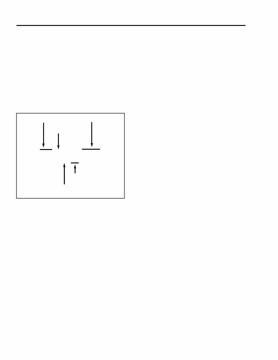
“Right” and “Left” are determined from a position
standing behind the unit and facing the direction of
travel.
GEHL Company reserves the right to make changes
or improvements in the design or construction of any
part of the unit without incurring the obligation to
install such changes on any unit previously delivered.
NOTE: On original tire replacement, company
policy prohibits the sale of replacement tires for
all GEHL machinery. Replacement wheel sets
are available and tire size information is called
out with the wheel sets to facilitate replacement
tire selection. ALL REPLACEMENT TIRES
MUST BE PURCHASED LOCALLY.
Grease fittings and common attaching hardware, such
as cotter pins, set screws, woodruff keys, screws, nuts,
etc., are included in the parts list, indented below the
part it is (they are) associated with, but NOT illustrat-
ed, except where a particular routing or special fas-
tening arrangement MUST be maintained. The hard-
ware listed is for mounting purposes and is NOT
included when the part is ordered for replacement.
Standard attaching hardware torque values are pro-
vided on the inside Back Cover. Unless otherwise
specified, all cap screws are Grade 5, cadmium or
zinc plated; hexagon nuts for Grade 5 cap screws or
bolts are Grade A.
List of Abbreviations Used in this Manual
AR As Required
ASY Assembly
CYL Cylinder
DIA Diameter
FT Foot or Feet
GR Grade
HYD Hydraulic
LH Left Hand
LT Left
NPTF National Pipe Threaded Fitting
NSS Not Sold Separately
RH Right Hand
RT Right
W/ With
883 J P 01 7378
Model Unit Number
Engine
Month
Year (N=97, P=98, Q=99, etc.)

883 Dynalift Table of Contents
Page Page
Introduction . . . . . . . . . . . . . . . . . . . .Inside Front Cover
Table Of Contents . . . . . . . . . . . . . . . . . . . . . . . . . . . . .1
Decal Locations . . . . . . . . . . . . . . . . . . . . . . . . . . . . . . .3
Chassis, Tanks & Covers Section
Operator’s Station
Outside Area & Inner Panels . . . . . . . . . . . . . . . . .14
Dash Area . . . . . . . . . . . . . . . . . . . . . . . . . . . . . . .16
Floor Area . . . . . . . . . . . . . . . . . . . . . . . . . . . . . .18
Fuel Tank/Front Inner Frame Area Group . . . . . . . . . .20
Rear Inner Frame Area Group . . . . . . . . . . . . . . . . . . .22
Hoods & Covers . . . . . . . . . . . . . . . . . . . . . . . . . . . . .24
Outrigger Assembly . . . . . . . . . . . . . . . . . . . . . . . . . . .26
Cab Assembly (No A/C) . . . . . . . . . . . . . . . . . . . . . . .28
Cab Air Conditioning . . . . . . . . . . . . . . . . . . . . . . . . . .32
Boom Components Section
Outer Boom Section Group . . . . . . . . . . . . . . . . . . . . .34
Intermediate Section Group . . . . . . . . . . . . . . . . . . . . .36
Inner Boom Section Group . . . . . . . . . . . . . . . . . . . . .38
Standard Carriage Attachment Group . . . . . . . . . . . . . .40
Fork Shift Carriage Attachment Group . . . . . . . . . . . . .42
Rotate Carriage Attachment Group . . . . . . . . . . . . . . .44
Swing Carriage Attachment Group . . . . . . . . . . . . . . . .46
Truss Boom & Bucket Attachment Group . . . . . . . . . .50
6 Ft. Mast Attachment (Old Style) . . . . . . . . . . . . . . . .52
6 Ft. Mast Attachment (New Style) . . . . . . . . . . . . . . .54
Axles & Service Brakes Section
Power Brake/Master Cylinder Assemmbly . . . . . . . . . .56
Axle Planetary & Wheel Group . . . . . . . . . . . . . . . . . .58
Brake Caliper Assembly . . . . . . . . . . . . . . . . . . . . . . .60
Axle Outer Knuckle End Group . . . . . . . . . . . . . . . . . .62
Axle Differential Carrier Group . . . . . . . . . . . . . . . . . .64
Electrical System Section
Main Electrical Schematic . . . . . . . . . . . . . . . . . . . . . .66
Light Package Wiring Hookup . . . . . . . . . . . . . . . . . . .74
Cab Enviroment Wiring Hookup w/o A/C . . . . . . . . . .78
Cab Enviroment Wiring Hookup w/ A/C . . . . . . . . . . .80
Ether Start Wiring Hookup . . . . . . . . . . . . . . . . . . . . .84
Hydraulic Systems Section
Tank Return & Manifold Plumbing . . . . . . . . . . . . . . .86
Brake Control Plumbing . . . . . . . . . . . . . . . . . . . . . . .88
Steering Plumbing . . . . . . . . . . . . . . . . . . . . . . . . . . . .90
Frame Level Plumbing . . . . . . . . . . . . . . . . . . . . . . . . .92
Boom Extend Plumbing . . . . . . . . . . . . . . . . . . . . . . . .94
Boom Lift Plumbing . . . . . . . . . . . . . . . . . . . . . . . . . .96
Boom Carrier Tilt/Slave Plumbing . . . . . . . . . . . . . . . .98
Auxilliary Hydraulic Plumbing . . . . . . . . . . . . . . . . .100
Fork Shift Carriage Attachment Plumbing . . . . . . . . .102
Rotate Carriage Attachment Plumbing . . . . . . . . . . . .104
Swing Carriage Attachment Plumbing . . . . . . . . . . . .106
Winch Attachment Plumbing . . . . . . . . . . . . . . . . . . .108
6 Ft. Mast Attachment Plumbing (Old Style) . . . . . . .110
6 Ft. Mast Attachment Plumbing (New Styyle) . . . . .112
Outriggers Option Plumbing (Ext. Lock Valves) . . . .114
Outriggers Option Plumbing (Int. Lock Valves) . . . . .116
Power Train
Transmission,
External Components Group . . . . . . . . . . . . . . . .118
Internal Components Group . . . . . . . . . . . . . . . .120
Radiator/Coolers Group . . . . . . . . . . . . . . . . . . . . . . .122
Air Intake Group . . . . . . . . . . . . . . . . . . . . . . . . . . . .124
Exhaust Group . . . . . . . . . . . . . . . . . . . . . . . . . . . . . .126
External Engine/Fuel Lines Group . . . . . . . . . . . . . . .128
Hydraulic Components Section
Steer Cylinder . . . . . . . . . . . . . . . . . . . . . . . . . . . . . .130
Frame Level Cylinders . . . . . . . . . . . . . . . . . . . . . . . .132
Boom Lift Cylinders . . . . . . . . . . . . . . . . . . . . . . . . .136
Boom Extend Cylinders . . . . . . . . . . . . . . . . . . . . . . .142
Carrier Slave Cylinder . . . . . . . . . . . . . . . . . . . . . . . .148
Attachment Tilt Cylinders . . . . . . . . . . . . . . . . . . . . .156
Outrigger Cylinders . . . . . . . . . . . . . . . . . . . . . . . . . .162
Fork Shift Cylinder . . . . . . . . . . . . . . . . . . . . . . . . . .166
Rotate Carriage Cylinder . . . . . . . . . . . . . . . . . . . . . .168
Swing Carriage Cylinder . . . . . . . . . . . . . . . . . . . . . .170
6 Ft. Mast Extend Cylinder (Old Style) . . . . . . . . . . .174
6 Ft. Mast Extend Cylinder (New Style) . . . . . . . . . .176
Gear Pump . . . . . . . . . . . . . . . . . . . . . . . . . . . . . . . . .178
Power Steering Motor . . . . . . . . . . . . . . . . . . . . . . . .182
Winch Assembly . . . . . . . . . . . . . . . . . . . . . . . . . . . .184
V40 Valve . . . . . . . . . . . . . . . . . . . . . . . . . . . . . . . . .186
V30 Valve . . . . . . . . . . . . . . . . . . . . . . . . . . . . . . . . .188
4-Way Joystick Controller . . . . . . . . . . . . . . . . . . . . .190
2-Way Joystick Controller . . . . . . . . . . . . . . . . . . . . .192
Frame Level Control Valve . . . . . . . . . . . . . . . . . . . .194
Outrigger Control Valve . . . . . . . . . . . . . . . . . . . . . . .196
Priority Flow Divider . . . . . . . . . . . . . . . . . . . . . . . . .198
2 GPM Flow Divider . . . . . . . . . . . . . . . . . . . . . . . . .200
Joystick Relief . . . . . . . . . . . . . . . . . . . . . . . . . . . . . .202
Outrigger Relief . . . . . . . . . . . . . . . . . . . . . . . . . . . . .204
Lock Valve . . . . . . . . . . . . . . . . . . . . . . . . . . . . . . . .206
Winch Relief . . . . . . . . . . . . . . . . . . . . . . . . . . . . . . .208
Steer Select Valve (Old Style) . . . . . . . . . . . . . . . . . .210
Steer Select Solenoid Valve (New Style) . . . . . . . . . .212
Miscellaneous Components Section
Numerical Index . . . . . . . . . . . . . . . . . . . . . . . . . . . .214
Standard Fasteners Table . . . . . . . . . . . . . . . . . . . . . .226
Hardware Torque Specs . . . . . . . . . . .Inside Back Cover
PRINTED IN U.S.A. 1 907365/AP1299

NOTES
907365/AP1299 2 PRINTED IN U.S.A.

883 Dynalift Decals
PRINTED IN U.S.A. 3 907365/AP1299
GENERAL INFORMATION
Decal Locations information is provided to assist in
the proper selection and application of new decals, in
the event the original decal(s) become(s) damaged or
the machine is repainted.
For correct replacement of decal(s) compare the loca-
tion illustrations to your machine before starting to
refinish the unit. Check-off each required decal using
the illustration reference number to find the part num-
ber, description and quantity in the list. Refer to the
appropriate illustration(s) for replacement location(s).
NEW DECAL APPLICATION
Before applying the new decals, surfaces must be free
from dirt, dust, grease and other foreign material. To
apply a solid-formed decal, remove the smaller por-
tion of the decal backing paper and apply this part of
the exposed adhesive backing to the clean surface
while maintaining proper position and alignment.
Slowly peel off the other portion of the backing paper
while applying hand pressure to smooth-out decal sur-
face. To apply a die-cut decal, first remove the back-
ing paper. Then, properly orient and position the decal
onto the clean mounting surface. After the decal is
firmly applied and smoothly pressed down, remove
the front covering paper.
PAINT FINISH
Use this list to order paint for refinishing:
For Units From S/N 7355 & Up Except 7357, 7358:
906213 One Gal. Yellow
906317 One Gal. Charcoal Grey
906214 6 (12 oz. Spray Cans) Yellow
906318 6 (12 oz. Spray Cans) Charcoal Grey
Decal Kits
L98861 S/N 7355 & Up Except 7357 & 7358
L500175 S/N thru 7354, including 7357, 7358
NOTE: Decals may be purchased in kits or
individually.
CAUTION
ALWAYS read and follow the safety precau-
tions on decals. Replace decals if they are
damaged, or if the unit is repainted. If repaint-
ing, BE SURE that all applicable decals are
affixed in their proper locations.
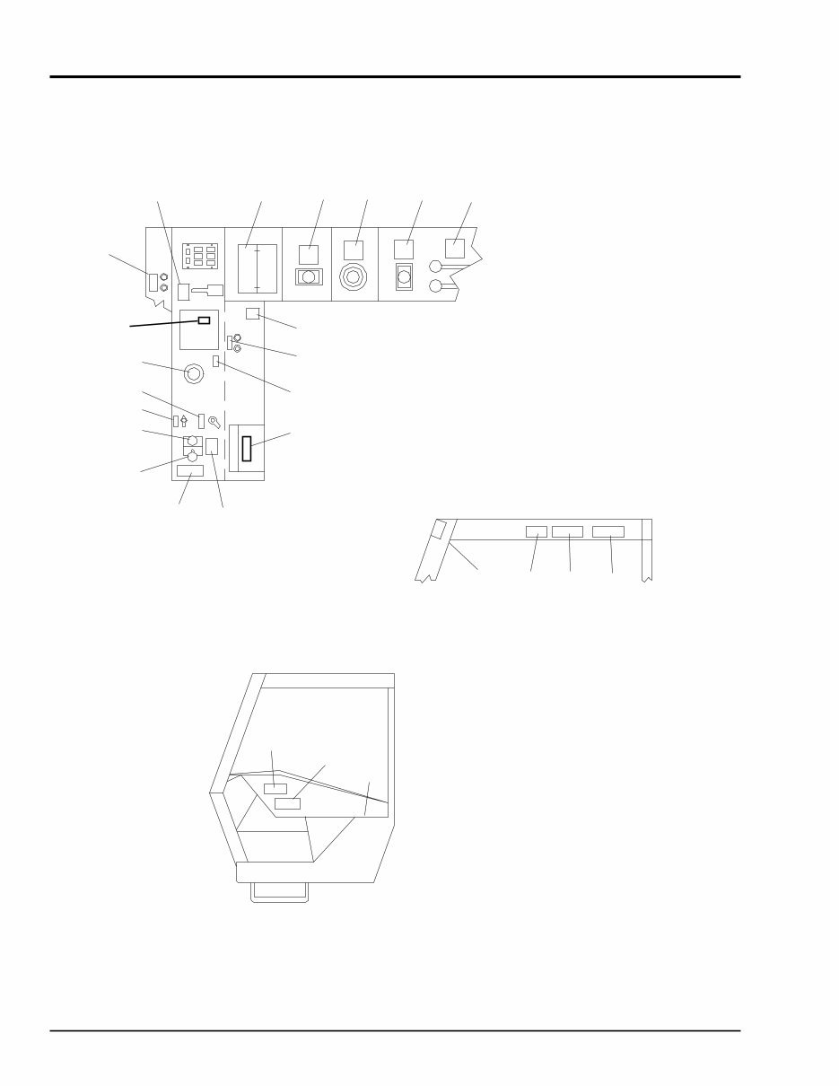
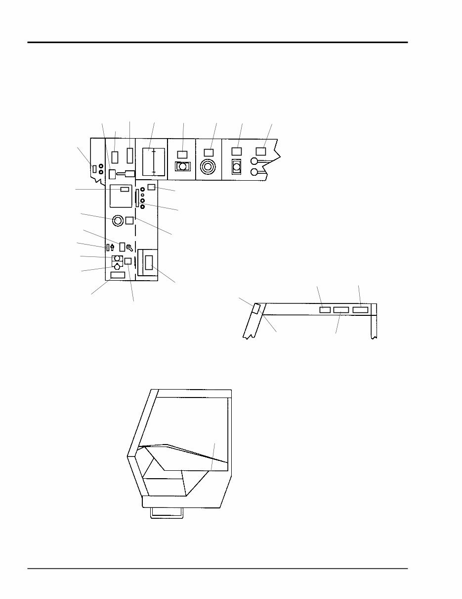
Decals 883 Dynalift
Inside Operator Station Area
Units S/N 7355 & Up, Except 7357, 7358
907365/AP1299 4 PRINTED IN U.S.A.
1011-77.dwg/83dec1.wmf
24 11
10 9 8 26
23
21
20
19
18
17
25
13
14
15
16
12
5
27
4
6 7
1
2
3
22

883 Dynalift Decals
Inside Operator Station Area
Units S/N 7355 & Up, Except 7357, 7358
PRINTED IN U.S.A. 5 907365/AP1299
NOTE: Decals may be ordered as kit or individually.
L98861 DECAL KIT - 883
01 L65934 BRAKE FLUID LEVEL . . . . . . . . . . 1
(On Seat Mount Panel)
02 L65928 DANGER - PERSONNEL LIFT . . . . 1
03 L66042 WARNING - TRUSS BOOM TILT . . 1
04 093475 WARNING - CARRY LOAD LOW . . 1
05 L65930 WARNING - MACHINE LEVEL . . . . 1
06 L65929 DANGER - HIGH VOLTAGE . . . . . . 1
07 L65948 DANGER - PANEL IN PLACE . . . . 1
08 L64810 FRAME LEVEL CONTROL. . . . . . . 1
09 L64812 BOOM CONTROL . . . . . . . . . . . . . 1
10 L65208 ATTACHMENT CONTROL . . . . . . . 1
11 L97963 LOAD CHART SET - INCL:
L65198 STD./ROTATE CARR. 883 . . . . . . 1
L65207 SWING CARR. 883 . . . . . . . . . . . . 1
L65648 WINCH - 883 . . . . . . . . . . . . . . . . 1
L65438 BUCKET - 883 . . . . . . . . . . . . . . . 1
L65594 6 FT. MAST EXTENSION 883 . . . . 1
12 094951 MADE IN U.S.A. . . . . . . . . . . . . . . 1
13 L65440 WARNING - SEAT BELT . . . . . . . . 1
14 L65922 OPER. MANUAL INSIDE . . . . . . . . 1
15 L68052 IGN. SW./HORN BUTTON . . . . . . . 1
16 L68513 IGN. SW/HORN BUTTON. . . . . . . . 1
17 L60936 F-N-R SHIFT . . . . . . . . . . . . . . . . . 1
18 L64945 1-2-3 SHIFT . . . . . . . . . . . . . . . . . . 1
19 L64797 CLUTCH DUMP SWITCH . . . . . . . 1
20 L64814 STEER SELECT . . . . . . . . . . . . . . 1
21 L66582 GEHL, 2” DIA. . . . . . . . . . . . . . . . . 1
22 L65923 WARNING - BRAKE FAILURE . . . . 1
23 L64643 HYD. PRESS. SETTINGS . . . . . . . 1
24 L65925 WARNING - PARK BRAKE. . . . . . . 1
25 L63690 WARNING - OPERATOR . . . . . . . . 1
26 L65138 OUTRIGGERS CONTROL . . . . . . . 1
27 L65512 AUTO-TROLL . . . . . . . . . . . . . . . . 1
Ref. Part Description Qty. Ref. Part Description Qty.
No. No. Req. No. No. Req.
907365/AP1299 6 PRINTED IN U.S.A.
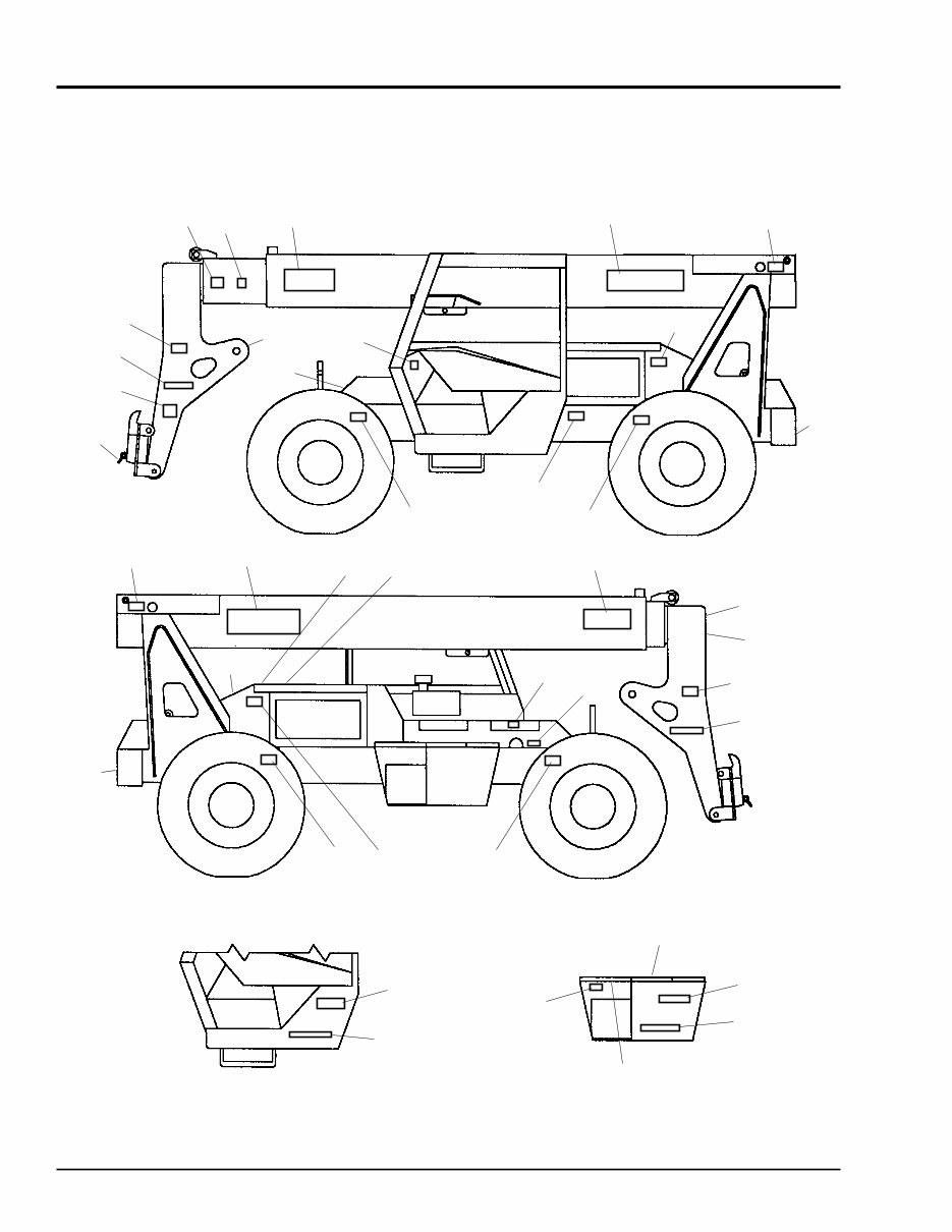
Decals 883 Dynalift
Frame & Boom Area
Units S/N 7355 & Up, Except 7357, 7358
590-5014/63dec2.tif
25
24
25
9
25
21
22
3 11
23
3
3
12
19 20
17
16
7
13
14
3
1
10
4
5
7
12
3
11
23
3
8
3
9
10
6
2
1
3
15
18

PRINTED IN U.S.A. 7 907365/AP1299
08 L65933 DANGER - JUMP START . . . . . . . . 1
09 L65932 WARNING - NO RIDERS . . . . . . . . 1
10 L65920 GREASE DAILY . . . . . . . . . . . . . . . 2
11 L65924 DANGER - ROTATE FAN . . . . . . . . 2
12 L66567 GEHL, 8.0” . . . . . . . . . . . . . . . . . . . 2
13 L66584 GEHL, 2.0” . . . . . . . . . . . . . . . . . . . 1
14 L65928 DANGER - PERSONNEL LIFT . . . . 1
15 L66613 DYNATTACH UNLOCK . . . . . . . . . 1
(Red Stripe)
16 L65921 HYD. OIL LEVELS . . . . . . . . . . . . . 1
17 072794 HYD. OIL FILL . . . . . . . . . . . . . . . . 1
18 072797 DIESEL FUEL . . . . . . . . . . . . . . . . 1
19 072798 COOLANT UNDER PRESS.. . . . . . 1
20 056859 ANTI-FREEZE . . . . . . . . . . . . . . . . 1
21 L65931 LUBE CHART . . . . . . . . . . . . . . . . 1
22 L68083 FILTER REFERENCE CHART . . . . 1
23 L66565 GEHL, 4.5” . . . . . . . . . . . . . . . . . . . 1
24 L66568 DYNALIFT, 2.0” . . . . . . . . . . . . . . . 2
25 L64012 AUTOTROL . . . . . . . . . . . . . . . . . . 2
NOTE: Decals may be purchased as kit or individually.
L98861 DECAL KIT - 883 . . . . . . . . . . . . . . 1
01 L66569 DYNATTACH, 1-1/8”. . . . . . . . . . . . 2
02 L65937 DYNATTACH DIAGRAM . . . . . . . . 1
03 L65927 WARNING - PINCH PONT . . . . . . 10
04 BOOM EXTEND MARKERS
(Operator Side)
L62573 NO. “6” . . . . . . . . . . . . . . . . . . . . . 1
L62574 NO. “8” . . . . . . . . . . . . . . . . . . . . . 1
L62575 NO. “10” . . . . . . . . . . . . . . . . . . . . 1
L62576 NO. “12” . . . . . . . . . . . . . . . . . . . . 1
L62577 NO. “14” . . . . . . . . . . . . . . . . . . . . 1
L62578 NO. “16” . . . . . . . . . . . . . . . . . . . . 1
L62579 NO. “18” . . . . . . . . . . . . . . . . . . . . 1
L62580 NO. “20” . . . . . . . . . . . . . . . . . . . . 1
L62581 NO. “22” . . . . . . . . . . . . . . . . . . . . 1
L62582 NO. “24” . . . . . . . . . . . . . . . . . . . . 1
05 L62583 ODD FT. MARKER (Oper. Side). . . 9
06 L65926 WARNING - CARRY LOAD LOW . . 1
07 L66579 883 . . . . . . . . . . . . . . . . . . . . . . . . 2
883 Dynalift Decals
Frame & Boom Area
Units S/N 7355 & Up, Except 7357, 7358
Ref. Part Description Qty. Ref. Part Description Qty.
No. No. Req. No. No. Req.
Decals 883 Dynalift
Inside Operator Station Area
Units Thru S/N 7354, Incl. 7357, 7358
907365/AP1299 8 PRINTED IN U.S.A.
1
4
27
5
6
7
23
24
11 10 9 8 26
12
15,16 or 29
14
2
25
17
18
19
20
21
22
13
1011-77/83dec1.tif
3
28
You're Reading a Preview
What's Included?
Fast Download Speeds
Online & Offline Access
Access PDF Contents & Bookmarks
Full Search Facility
Print one or all pages of your manual
$28.99
$37.99
Gehl 883 Dynalift Telescopic Forklift Parts Manual
Viewed 60 Times Today

What's Included?
Fast Download Speeds
Online & Offline Access
Access PDF Contents & Bookmarks
Full Search Facility
Print one or all pages of your manual
$28.99
$37.99

Secure transaction
What's Included?
Fast Download Speeds
Online & Offline Access
Access PDF Contents & Bookmarks
Full Search Facility
Print one or all pages of your manual
Description
The Gehl 883 Dynalift Telescopic Forklift Parts Manual is a comprehensive guide designed for both professional mechanics and DIYers. It provides detailed instructions and diagrams to help you understand and repair various components of your machine.
- This manual covers all aspects of the Gehl 883 Dynalift Telescopic Forklift, including troubleshooting, repair, and maintenance procedures.
- With step-by-step instructions and highly detailed exploded diagrams, you'll be able to complete the required job correctly and efficiently.
- This manual is suitable for both professional mechanics and DIYers, making it a valuable resource for anyone who needs to work on their Gehl 883 Dynalift Telescopic Forklift.
No matter your level of experience, this manual will provide you with the information you need to keep your Gehl 883 Dynalift Telescopic Forklift running smoothly and efficiently.


