Maintenance AC MOTOR CONTROLLERS/DISPLAY PANEL DESCRIPTION, CHECKS, ADJUSTMENTS, AND TROUBLESHOOTING NDR035EA, NR045EA [C861]; NDR030EA, NR035-040EA [D815] PART NO. 524233337 2200 YRM 1190
SAFETY PRECAUTIONS MAINTENANCE AND REPAIR • When lifting parts or assemblies, make sure all slings, chains, or cables are correctly fas- tened, and that the load being lifted is balanced. Make sure the crane, cables, and chains have the capacity to support the weight of the load. • Do not lift heavy parts by hand, use a lifting mechanism. • Wear safety glasses. • DISCONNECT THE BATTERY CONNECTOR before doing any maintenance or repair on electric lift trucks. Disconnect the battery ground cable on internal combustion lift trucks. • Always use correct blocks to prevent the unit from rolling or falling. See HOW TO PUT THE LIFT TRUCK ON BLOCKS in the Operating Manual or the Periodic Maintenance section. • Keep the unit clean and the working area clean and orderly. • Use the correct tools for the job. • Keep the tools clean and in good condition. • Always use YALE APPROVED parts when making repairs. Replacement parts must meet or exceed the specifications of the original equipment manufacturer. • Make sure all nuts, bolts, snap rings, and other fastening devices are removed before using force to remove parts. • Always fasten a DO NOT OPERATE tag to the controls of the unit when making repairs, or if the unit needs repairs. • Be sure to follow the WARNING and CAUTION notes in the instructions. • Gasoline, Liquid Petroleum Gas (LPG), Compressed Natural Gas (CNG), and Diesel fuel are flammable. Be sure to follow the necessary safety precautions when handling these fuels and when working on these fuel systems. • Batteries generate flammable gas when they are being charged. Keep fire and sparks away from the area. Make sure the area is well ventilated. NOTE: The following symbols and words indicate safety information in this manual: WARNING Indicates a condition that can cause immediate death or injury! CAUTION Indicates a condition that can cause property damage!
Table of Contents AC Motor Controllers/Display Panel TABLE OF CONTENTS (Continued) Moving Through Menu Selections ................................................................................................................... 90 Access to Service Functions ........................................................................................................................... 90 Service Functions ........................................................................................................................................... 91 Connector Pin-Outs ............................................................................................................................................. 92 System Logic Diagram ........................................................................................................................................ 99 This section is for the following models: NDR035EA, NR045EA [C861]; NDR030EA, NR035-040EA [D815] ii
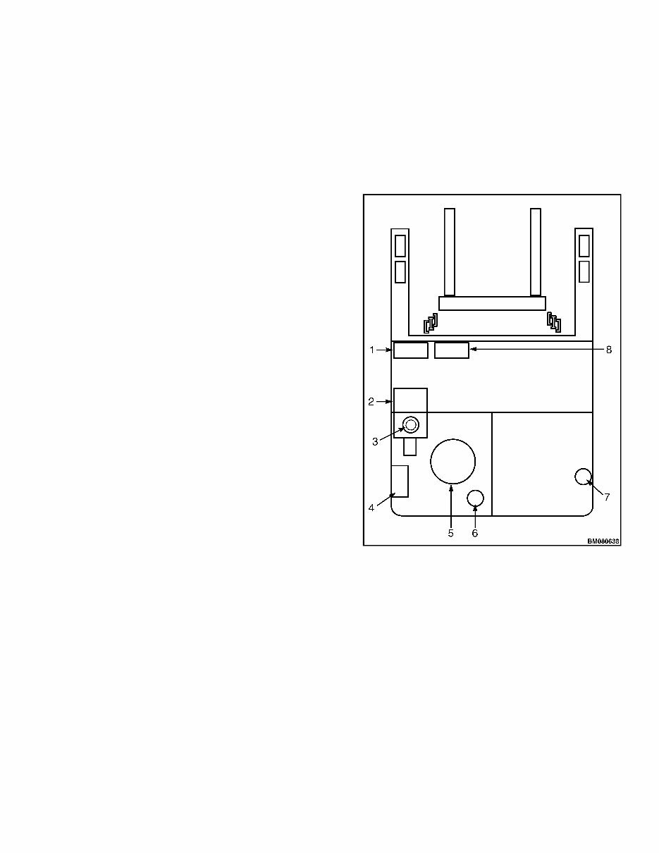
2200 YRM 1190 Description Description GENERAL The alternating current (AC) system consists of AC mo- tors, motor controller(s), a master controller, and a dash display. The major difference between the AC system and the direct current (DC) system is the master con- troller performs many of the same functions that pre- viously were performed in the motor controllers on the DC system. AC Motors The AC motors are three-phase AC induction motors. They do not include motor brushes or commutators. An AC induction motor operates on three-phase AC power provided directly by the motor controller. The motor’s speed is controlled by the motor controller and can be changed by changing the frequency of the AC power provided to the motor. A speed sensor is built into the rear motor bearing, which provides RPM and direction feedback to the motor controller. The motor controller continuously monitors motor direction and speed. Us- ing this feedback, the AC motor control system can pro- vide much better vehicle top speed control than is avail- able with DC SEM systems. The AC motors also have thermal sensors embedded in the motor windings that are continuously monitored by the motor controllers. Motor Controllers The motor controllers receive power from the truck’s battery and convert it into three-phase AC power at the frequencies and currents necessary to drive the respec- tive pump and/or traction motor. Each AC induction mo- tor provides feedback of speed, rotation direction, and temperature directly to the motor controller. The two motor controllers used to power the traction motor and hydraulic pump motor are very similar. The primary mo- tor controller difference is in the power output rating. The motor controller logic board receives power from the key switch. Power to the motors can be interrupted indirectly by the key switch. The motor controllers get motor speed and temperature information directly from the motors. The motor controllers do not get any other input from the truck. The master controller relays speed, acceleration, and direction commands to the motor controllers. See Figure 1 and Figure 2 for the component locations. 1. TRACTION CONTROLLER 2. LIFT MOTOR 3. AUXILIARY PUMP AND MOTOR 4. MASTER AND STEERING CONTROLLERS 5. TRACTION MOTOR 6. MDU STEER MOTOR 7. CASTER STEER MOTOR (OPTIONAL) 8. PUMP MOTOR CONTROLLER Figure 1. Component Location (Top View) 1
You're Reading a Preview
What's Included?
Lifetime Access
Fast Download Speeds
Offline Viewing
Access Contents & Bookmarks
Full Search Facility
Print one or all pages of your manual
$46.99
YALE (A295) NR35-40DA, NDR30DA Lift Truck Service Repair Manual
If you are facing trouble with YALE (A295) NR35-40DA, NDR30DA LIFT TRUCK maintenance or worried about its failure, we have a solution for you. Our YALE (A295) NR35-40DA, NDR30DA LIFT TRUCK service repair manual is available electronically, offering rich maintenance knowledge that is practical and easy to access. Whether you are a professional mechanic or a DIY enthusiast, this manual is a valuable resource for you.
The manual covers a wide range of aspects including frame, AC motor repair, master drive unit, steering system, brake system, hydraulic system, troubleshooting and adjustments using the AC controls program, electrical system, supervisor interface - standard, technician interface - standard, supervisor interface - premium, technician interface - premium, AC motor controllers/display panel, industrial battery, lift cylinders, mast description, mast repairs, reach carriages, metric and inch (SAE) fasteners, periodic maintenance, capacities and specifications, and diagrams.
File Format: .PDF
Compatible: All Versions of Windows & Mac
Language: English
Requirements: Adobe Reader & Win
With this electronic manual, you will have a comprehensive guide to YALE (A295) NR35-40DA, NDR30DA LIFT TRUCK maintenance at your fingertips. It is practical, easy to carry, and can be accessed anytime and anywhere, making it the perfect partner for your work. Don't miss out on this valuable resource that can help you effectively maintain and repair your YALE (A295) NR35-40DA, NDR30DA LIFT TRUCK.
Reviews
Q&A
Recently Viewed
5,521,897Happy Clients
2,594,462eManuals
1,120,453Trusted Sellers
15Years in Business
Price:
Actual Price:
YALE (A295) NR35-40DA, NDR30DA Lift Truck Service Repair Manual






 Lifetime Access




