

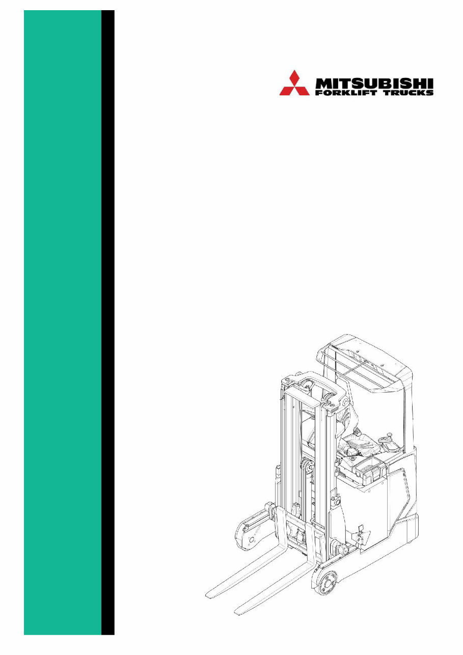
SERVICE MANUAL
RB14-25N2(S)(C)(H)(X)
622075
English 2014
© Mitsubishi Forklift Trucks 2014. All rights reserved. Revision: A Document ID: 622075 2 (442)
RB14-25N2(S)(C)(H)(X) Service Manual
Only adequately trained service persons are allowed to carry out service operations. The terms of the
warranty prescribe appropriate maintenance of the truck. All spare parts must be original ones.
It is recommended that you sign a maintenance agreement with the truck dealer, who can also supply spare
parts. Only professional service ensures long-term, trouble-free truck operation. Service program monitoring
becomes easier if you enter the service dates in a service logbook. Contact our service organisation or your
truck dealer for qualified, authorized and efficient maintenance service.
Copyright © 2014 by Mitsubishi Forklift Trucks, bv. All rights reserved.
Mitsubishi Forklift Trucks® is a registered trademark of Mitsubishi Heavy Industries®, Inc. All brand or product
names are or may be trademarks of, and are used to identify products and services of, their respective
owners.
Unauthorized copying and lending are prohibited.
Mitsubishi Caterpillar Forklift
Asia Pte. Ltd.
RCB No.: 199203169H
No. 1, Tuas West Street
Singapore 637444
MCFA MCFE B.V.
2121 W. Sam Houston Pkwy. N. Hefbrugweg 77
Houston, TX 77043-2305 1332 AM Almere
USA The Netherlands
Approvals and version history
REVISION DATE DESCRIPTION OF CHANGE APPROVED BY
A 4.11.2014 First issue
R&D
Original instructions ___X___ / Translation of the original instructions _______

© Mitsubishi Forklift Trucks 2014. All rights reserved. Revision: A Document ID: 622075 3 (442)
RB14-25N2(S)(C)(H)(X) Service Manual
Contents
Contents ............................................................................................................................. 3
1 Foreword ................................................................................................................ 11
2 How to read this manual ....................................................................................... 12
2.1 Safety-related signs ................................................................................. 12
2.2 Symbols and abbreviations ...................................................................... 12
2.2.1 Safety symbols................................................................................................ 12
2.2.2 Other symbols and abbreviations .................................................................... 14
2.3 Units ......................................................................................................... 14
3 Safety instructions ................................................................................................ 15
3.1 Service area safety .................................................................................. 15
3.2 Personal safety ........................................................................................ 16
3.3 Work safety .............................................................................................. 16
4 General information .............................................................................................. 19
4.1 Truck model covered by this manual ....................................................... 19
4.2 Identification plates on the truck .............................................................. 19
4.3 Overview of the truck ............................................................................... 21
4.3.1 Operating devices ........................................................................................... 21
4.3.2 Control panel................................................................................................... 22
4.3.3 Steering wheel ................................................................................................ 23
4.3.4 Arm rest .......................................................................................................... 24
4.3.5 Display panel .................................................................................................. 25
4.3.6 Truck operation modes.................................................................................... 27
4.3.7 Truck display................................................................................................... 27
4.3.7.1 Display control buttons .................................................................................... 28
4.3.7.2 Main view of the truck display.......................................................................... 29
4.3.7.3 Hierarchy of the truck display menus............................................................... 38
4.3.8 Pedals............................................................................................................. 42
4.3.9 Operator’s seat ............................................................................................... 44
4.3.10 Operating position ........................................................................................... 45
4.3.11 Driving direction .............................................................................................. 46
4.3.12 Motor, hydraulic system and electrical system................................................. 47
4.3.12.1 Instrument panel ............................................................................................. 48
4.3.12.2 Hydraulic system............................................................................................. 49
4.3.12.3 Motor compartment ......................................................................................... 50
4.3.13 Sensors........................................................................................................... 50
4.3.14 Reach carriage................................................................................................ 52
4.3.15 Mast unit ......................................................................................................... 52
4.3.16 Load support ................................................................................................... 53
5 Mechanical maintenance ...................................................................................... 54
5.1 Lifting points ............................................................................................. 54
5.1.1 Jack points ...................................................................................................... 54

© Mitsubishi Forklift Trucks 2014. All rights reserved. Revision: A Document ID: 622075 4 (442)
RB14-25N2(S)(C)(H)(X) Service Manual
5.1.2 Hoist points ..................................................................................................... 55
5.2 Transportation .......................................................................................... 55
5.3 Assembly and commissioning.................................................................. 58
5.3.1 Install the mast unit ......................................................................................... 58
5.4 Order spare parts ..................................................................................... 62
5.5 Truck covers............................................................................................. 62
5.5.1 Remove the machinery cover .......................................................................... 63
5.5.2 Remove the front bumper................................................................................ 64
5.5.3 Remove the floor plate .................................................................................... 64
5.5.4 Open the machinery top cover ........................................................................ 65
5.5.5 Open the instrument panel .............................................................................. 66
5.5.6 Remove the instrument panel cover ................................................................ 67
5.5.7 Remove the control panel ............................................................................... 68
5.5.8 Remove the cup holder ................................................................................... 68
5.5.9 Remove the reach carriage cover.................................................................... 68
5.6 Steering wheel ......................................................................................... 69
5.6.1 Remove the steering wheel ............................................................................. 69
5.7 Transmission gear.................................................................................... 70
5.7.1 Remove the transmission gear ........................................................................ 71
5.8 Slewing bearing........................................................................................ 72
5.8.1 Lubricate the slewing bearing.......................................................................... 72
5.9 Traction wheel .......................................................................................... 73
5.9.1 Disassemble the traction wheel ....................................................................... 74
5.9.1.1 Replace the wheel shaft bolts.......................................................................... 74
5.9.2 Assemble the traction wheel............................................................................ 76
5.10 Corner supports ....................................................................................... 76
5.10.1 Replace the corner supports ........................................................................... 77
5.11 Load wheels ............................................................................................. 77
5.11.1 Remove the load wheels ................................................................................. 78
5.12 Battery roller frame................................................................................... 79
5.12.1 Remove the battery roller frame ...................................................................... 79
5.13 Reach carriage ......................................................................................... 80
5.13.1 Lubricate the rollers of the reach carriage ....................................................... 80
5.13.2 Adjust the guidance rollers of the reach carriage ............................................. 81
5.13.3 Sensors of the reach carriage ......................................................................... 84
5.13.4 Remove the reach carriage ............................................................................. 84
5.13.5 Remove the reach cylinder.............................................................................. 86
5.13.6 Replace the reach carriage hoses ................................................................... 87
5.14 Mast unit ................................................................................................... 92
5.14.1 Detailed construction....................................................................................... 93
5.14.2 Mast unit maintenance .................................................................................... 94
5.14.2.1 Daily maintenance........................................................................................... 94
5.14.2.2 Monthly maintenance ...................................................................................... 94
5.14.2.3 Annual maintenance (600 h) ........................................................................... 94
5.14.3 Lubricant recommendations ............................................................................ 95
5.14.3.1 Mast chains..................................................................................................... 95
5.14.3.2 Mast channels ................................................................................................. 95
5.14.4 Remove the lifting carriage.............................................................................. 96
5.14.5 Remove the mast unit ..................................................................................... 99

© Mitsubishi Forklift Trucks 2014. All rights reserved. Revision: A Document ID: 622075 5 (442)
RB14-25N2(S)(C)(H)(X) Service Manual
5.14.6 Disassemble the mast unit ............................................................................ 102
5.14.7 Fork inspection.............................................................................................. 108
5.14.8 Mast chains................................................................................................... 112
5.14.8.1 Inspect the mast chains................................................................................. 113
5.14.8.2 Check the tension of the mast chains ............................................................ 119
5.14.8.3 Adjust the mast chains .................................................................................. 120
5.14.8.4 Replace the mast chains ............................................................................... 120
5.14.9 Guidance rollers ............................................................................................ 123
5.14.9.1 Adjust the guidance rollers ............................................................................ 124
5.14.9.2 Replace the guidance rollers ......................................................................... 125
5.14.10 Main rollers ................................................................................................... 127
5.14.10.1 Replace the main rollers................................................................................ 127
5.14.11 Free lift cylinder............................................................................................. 129
5.14.11.1 Replace the free lift cylinder .......................................................................... 129
5.14.11.2 Sealing housing of the free lift cylinder .......................................................... 132
5.14.11.3 Bleed out the air from the free lift cylinder ..................................................... 133
5.14.12 Side cylinders................................................................................................ 135
5.14.12.1 Replace the side cylinders ............................................................................ 136
5.14.12.2 Sealing housing of the side cylinder .............................................................. 139
5.14.12.3 Bleed out the air from the side cylinders ........................................................ 141
5.14.13 Tilt cylinders .................................................................................................. 143
5.14.13.1 Remove the tilt cylinders ............................................................................... 143
5.14.13.2 Sealing housing of the tilt cylinder ................................................................. 145
5.14.14 Sideshift cylinder ........................................................................................... 146
5.14.14.1 Remove the piston of the sideshift cylinder ................................................... 147
5.14.14.2 Sealing housing of the sideshift cylinder ........................................................ 148
5.15 Load support .......................................................................................... 149
5.15.1 Remove the load support .............................................................................. 149
5.16 Arm rest.................................................................................................. 150
5.16.1 Remove the arm rest ..................................................................................... 150
5.16.2 Open the arm rest ......................................................................................... 151
5.16.3 Remove the arm rest levers .......................................................................... 151
5.16.4 Remove the arm rest buttons ........................................................................ 152
5.17 Operator’s seat....................................................................................... 153
5.17.1 Replace the seat switch ................................................................................ 153
6 Electrical operation ............................................................................................. 155
6.1 How to use the schematic diagram........................................................ 155
6.2 Power source ......................................................................................... 158
6.3 Safety circuit (emergency stop button) .................................................. 158
6.4 Key switch .............................................................................................. 158
6.5 Traction .................................................................................................. 159
7 Battery maintenance ........................................................................................... 160
7.1 Safety regulations concerning the handling of lead-acid batteries ........ 161
7.2 Battery maintenance .............................................................................. 162
7.2.1 Daily maintenance......................................................................................... 162

© Mitsubishi Forklift Trucks 2014. All rights reserved. Revision: A Document ID: 622075 6 (442)
RB14-25N2(S)(C)(H)(X) Service Manual
7.2.2 Weekly maintenance ..................................................................................... 162
7.2.3 Monthly maintenance .................................................................................... 162
7.2.4 Annual maintenance ..................................................................................... 163
7.3 Recharge the battery.............................................................................. 163
7.4 Measure the specific gravity of the battery ............................................ 166
7.5 Replace the battery ................................................................................ 166
7.5.1 Guide the battery connector cables ............................................................... 170
7.6 Quick battery replacement ..................................................................... 171
8 Electric system maintenance ............................................................................. 172
8.1 Display panel .......................................................................................... 172
8.1.1 Emergency stop button ................................................................................. 173
8.1.1.1 Emergency stop button functionality check.................................................... 173
8.1.2 Key switch..................................................................................................... 174
8.1.2.1 Key switch functionality check ....................................................................... 174
8.2 Pedals .................................................................................................... 175
8.2.1 Operator presence pedal............................................................................... 175
8.2.1.1 Operator presence pedal functionality check ................................................. 176
8.2.1.2 Remove the operator presence pedal ........................................................... 176
8.2.2 Acceleration pedal......................................................................................... 177
8.2.2.1 Acceleration pedal functionality check ........................................................... 178
8.2.2.2 Remove the acceleration pedal ..................................................................... 178
8.2.3 Brake pedal ................................................................................................... 179
8.2.3.1 Brake pedal functionality check ..................................................................... 180
8.2.3.2 Remove the brake pedal ............................................................................... 180
8.3 Instrument panel .................................................................................... 181
8.3.1 Discharge the controllers............................................................................... 182
8.3.2 Vehicle controller........................................................................................... 183
8.3.3 Vehicle controller connectors ........................................................................ 183
8.3.3.1 CNA external connector ................................................................................ 184
8.3.3.2 CNB external connector ................................................................................ 186
8.3.4 Traction controller ......................................................................................... 187
8.3.5 Traction controller connectors ....................................................................... 188
8.3.5.1 CNA external connector ................................................................................ 189
8.3.5.2 Description of the power connections ............................................................ 190
8.3.6 Pump controller ............................................................................................. 190
8.3.7 Pump controller connectors........................................................................... 191
8.3.7.1 CNA external connector ................................................................................ 192
8.3.7.2 Description of the power connections ............................................................ 193
8.3.8 Steering controller ......................................................................................... 194
8.3.9 Steering controller connectors ....................................................................... 194
8.3.9.1 CNA external connector ................................................................................ 195
8.3.9.1 Description of the power connections ............................................................ 196
8.3.10 Fuses ............................................................................................................ 197
8.3.11 Remove the gas spring of the instrument panel ............................................. 199
8.4 Motor compartment ................................................................................ 200
8.4.1 Traction motor ............................................................................................... 201

© Mitsubishi Forklift Trucks 2014. All rights reserved. Revision: A Document ID: 622075 7 (442)
RB14-25N2(S)(C)(H)(X) Service Manual
8.4.1.1 Remove the traction motor ............................................................................ 202
8.4.1.2 Temperature sensor check............................................................................ 203
8.4.1.3 HALL sensor ................................................................................................. 204
8.4.2 Steering motor .............................................................................................. 205
8.4.2.1 Remove the steering motor ........................................................................... 206
8.4.2.2 Temperature sensor check............................................................................ 207
8.4.2.3 HALL sensor ................................................................................................. 208
8.4.3 Magnetic brake ............................................................................................. 210
8.4.3.1 Coil resistance measurement ........................................................................ 210
8.4.3.2 Install the magnetic brake ............................................................................. 211
8.4.3.3 Adjust the air gap of the magnetic brake ....................................................... 212
8.4.4 Release the magnetic brake manually........................................................... 212
8.5 Pump motor............................................................................................ 213
8.5.1 Pump motor (Standard model) ...................................................................... 213
8.5.2 Pump motor (High performance model)......................................................... 214
8.5.3 Replace the HALL sensor ............................................................................. 215
8.6 Sensors .................................................................................................. 216
8.6.1 Steering wheel sensor................................................................................... 216
8.6.1.1 Steering wheel sensor functionality check ..................................................... 216
8.6.1.2 Steering control safety circuit check .............................................................. 217
8.6.2 Steering reference sensor ............................................................................. 219
8.6.2.1 Steering reference sensor functionality check ............................................... 219
8.6.3 Reach end stop, retract limit, retract end stop and reach limit switch ............. 220
8.6.3.1 Reach end stop, retract limit, retract end stop and reach limit switch
functionality check......................................................................................... 220
8.6.4 Battery lock sensor........................................................................................ 221
8.6.4.1 Battery lock sensor functionality check .......................................................... 221
8.6.5 Pressure sensor ............................................................................................ 222
8.6.5.1 Pressure sensor functionality check .............................................................. 222
8.6.6 Height reference sensor ................................................................................ 223
8.6.6.1 Height reference sensor functionality check .................................................. 223
9 Electric system adjustments and measurements ............................................ 224
9.1 Calibrate the arm rest levers .................................................................. 224
9.2 Insulation resistance test ....................................................................... 224
9.2.1 Test voltage .................................................................................................. 224
9.2.2 Checking the insulation tester ....................................................................... 224
9.2.3 Measure the insulation resistance ................................................................. 225
9.2.3.1 Insulation resistance of the truck ................................................................... 225
9.2.3.2 Insulation resistance of the battery ................................................................ 226
10 Hydraulic operation ............................................................................................. 227
10.1 Hydraulic symbols .................................................................................. 232
10.2 Hydraulic oil recommendations .............................................................. 233
10.3 Maintenance points of the hydraulic system .......................................... 234
10.3.1 Replace the hydraulic oil return filter (sieve) .................................................. 235
10.3.2 Clean the hydraulic oil suction filter ............................................................... 236

© Mitsubishi Forklift Trucks 2014. All rights reserved. Revision: A Document ID: 622075 8 (442)
RB14-25N2(S)(C)(H)(X) Service Manual
10.4 Hydraulic system.................................................................................... 237
10.4.1 Disassemble the hydraulic system ................................................................ 238
10.5 Hydraulic valve unit ................................................................................ 239
10.5.1 Valve M1 ....................................................................................................... 242
10.5.2 Valve M3, M4, M7 and M8 ............................................................................ 243
10.5.3 Valve M2, M5, M6, M9 and M10.................................................................... 243
10.5.4 Emergency lowering valve ............................................................................ 243
10.5.5 Set the lifting pressure................................................................................... 243
10.5.6 Disassemble the valves................................................................................. 245
11 TruckTool Diagnostics ........................................................................................ 246
12 Parameter descriptions ...................................................................................... 247
12.1 VCM ....................................................................................................... 247
12.2 Traction controller .................................................................................. 260
12.3 Pump controller ...................................................................................... 269
12.4 EPS controller ........................................................................................ 273
13 Alarm codes ......................................................................................................... 277
13.1 VCM ....................................................................................................... 277
13.1.1 VCM master .................................................................................................. 277
13.1.2 VCM slave .................................................................................................... 291
13.2 Traction controller .................................................................................. 306
13.3 Pump controller ...................................................................................... 321
13.4 EPS ........................................................................................................ 333
13.4.1 EPS master ................................................................................................... 333
13.4.2 EPS slave ..................................................................................................... 345
14 Service data ......................................................................................................... 359
14.1 Special tightening torques ...................................................................... 359
14.2 Tightening torque for standard bolts and nuts ....................................... 359
14.3 Maintenance check list ........................................................................... 361
14.4 Lubrication.............................................................................................. 365
14.4.1 Hydraulic oil .................................................................................................. 365
14.4.2 Transmission oil ............................................................................................ 365
14.5 Special tools ........................................................................................... 366
15 Options ................................................................................................................. 369
15.1 Special color labels ................................................................................ 371
15.2 Customer design labels ......................................................................... 371
15.3 Display languages .................................................................................. 372
15.4 Accessory rack ....................................................................................... 373
15.4.1 Install the accessory rack .............................................................................. 374
15.4.2 Install the list bracket..................................................................................... 374
15.4.3 Install the computer rack ............................................................................... 375
15.4.4 Install the rear view mirror ............................................................................. 375
15.5 Accessory rack under the truck floor...................................................... 376
15.5.1 Install the accessory rack under the floor ...................................................... 376

© Mitsubishi Forklift Trucks 2014. All rights reserved. Revision: A Document ID: 622075 9 (442)
RB14-25N2(S)(C)(H)(X) Service Manual
15.6 Reading lamp ......................................................................................... 376
15.6.1 Install the reading lamp ................................................................................. 377
15.7 Audio system.......................................................................................... 378
15.7.1 Install the audio system................................................................................. 378
15.8 Warning light .......................................................................................... 380
15.8.1 Install the warning light .................................................................................. 380
15.9 Working lights......................................................................................... 382
15.9.1 Install the working lights ................................................................................ 382
15.10 Operator compartment fan ..................................................................... 384
15.10.1 Install the operator compartment fan ............................................................. 384
15.11 Drive alarm (programmable) .................................................................. 386
15.11.1 Install the drive alarm .................................................................................... 386
15.12 Steel safety net for overhead guard ....................................................... 387
15.12.1 Install the steel safety net to the overhead guard........................................... 387
15.13 Plexiglass safety cover for the overhead guard ..................................... 389
15.13.1 Install the plexiglass safety cover to the overhead guard ............................... 389
15.14 Left shoulder protection plate................................................................. 391
15.14.1 Install the left shoulder protection plate ......................................................... 391
15.15 Fire extinguisher..................................................................................... 392
15.15.1 Install the fire extinguisher............................................................................. 392
15.16 Cold storage modification ...................................................................... 394
15.17 Hot storage modification ........................................................................ 395
15.18 Current output ........................................................................................ 395
15.18.1 Install the DC-DC converter........................................................................... 395
15.19 Quick battery changing device for 2 batteries........................................ 397
15.19.1 Remove an empty battery with the battery changing device for 2
batteries ........................................................................................................ 398
15.19.2 Install a recharged battery with the battery changing device for 2
batteries ........................................................................................................ 400
15.20 Battery connector + cables .................................................................... 403
15.20.1 Replace the battery connector....................................................................... 403
15.21 Charger connector ................................................................................. 405
15.21.1 Replace the charger connector ..................................................................... 405
15.22 Extra valve with hosing to fork carriage ................................................. 406
15.23 Fork positioner with sideshift.................................................................. 407
15.24 Fork carriage strengthening part ............................................................ 407
15.25 Fork camera with 7” LCD color display .................................................. 408
15.26 Telescopic forks ..................................................................................... 409
15.27 Sideshift and tilt centering ...................................................................... 410
15.27.1 Sideshift centering direction, sideshift centering midpoint and tilt
centering sensor ........................................................................................... 410
15.27.1.1 Sideshift centering direction, sideshift centering midpoint and tilt
centering sensor functionality check .............................................................. 411
15.28 Load weight indicator ............................................................................. 412
15.29 Electric load wheel brakes ..................................................................... 413
15.30 Lowering cut-off...................................................................................... 414
15.31 Operator’s seat options and accessories ............................................... 415
15.31.1 Arm rest ........................................................................................................ 415

© Mitsubishi Forklift Trucks 2014. All rights reserved. Revision: A Document ID: 622075 10 (442)
RB14-25N2(S)(C)(H)(X) Service Manual
15.31.2 Backrest extension for MSG65/MSG75 ......................................................... 416
15.31.2.1 Backrest extension adjustment...................................................................... 416
15.31.3 Seat belt for MSG20 seat .............................................................................. 417
15.31.3.1 Install the seat belt ........................................................................................ 417
15.32 PIN code access to the Start switch ...................................................... 418
15.33 Lifting height pre-selection ..................................................................... 419
15.33.1 How to unstack with the lifting height pre-selection........................................ 420
15.33.2 How to stack with the lifting height pre-selection ........................................... 421
16 Technical specification ....................................................................................... 422
16.1 RB14N2S, RB14N2HS, RB16N2S, RB16N2HS and RB16N2 .............. 423
16.2 RB16N2H, RB16N2C, RB16N2HC, RB20N2H, RB20N2X and
RB25N2X ............................................................................................... 426
16.3 Mast heights ........................................................................................... 428
17 Index ..................................................................................................................... 430
APPENDIX A: Stickers................................................................................................... 433
You're Reading a Preview
What's Included?
 Lifetime Access
Fast Download Speeds
Online & Offline Access
Access PDF Contents & Bookmarks
Full Search Facility
Print one or all pages of your manual
$48.99
Mitsubishi Reach Truck RB14N2, RB16N2, RB20N2, RB25N2 (H)(S)(C)(X) Workshop Service Manual
Viewed 43 Times Today

What's Included?
Lifetime Access
Fast Download Speeds
Online & Offline Access
Access PDF Contents & Bookmarks
Full Search Facility
Print one or all pages of your manual
$48.99

Secure transaction
What's Included?
Lifetime Access
Fast Download Speeds
Online & Offline Access
Access PDF Contents & Bookmarks
Full Search Facility
Print one or all pages of your manual
Description
Illustrated Factory Workshop Service Manual for Mitsubishi Reach Truck RB-Series
- Original factory manuals for Mitsubishi Lift Trucks contain high-quality images, circuit diagrams, and instructions for operating, maintaining, and repairing your truck.
- All Manuals are Printable, without restrictions, contain Searchable Text, and bookmarks.
Covered models:
- RB14N2HS
- RB14N2S
- RB16N2
- RB16N2C
- RB16N2H
- RB16N2HC
- RB16N2HS
- RB16N2S
- RB20N2H
- RB20N2X
- RB25N2X
Format: 432 Pages
Language: English
Contents:
- Foreword
- How to read this manual
- Safety-related signs
- Symbols and abbreviations
- Safety symbols
- Other symbols and abbreviations
- Units
- Safety instructions
- Service area safety
- Personal safety
- Work safety
- General information
- Truck model covered by this manual
- Identification plates on the truck
- Overview of the truck
- Operating devices
- Control panel
- Steering wheel
- Armrest
- Display panel
- Truck operation modes
- Truck display
- Display control buttons
- Main view of the truck display
- Hierarchy of the truck display menus
- Pedals
- Operators seat
- Operating position
- Driving direction
- Motor, hydraulic system, and electrical system
- Instrument panel
- Hydraulic system
- Motor compartment
- Sensors
- Reach carriage
- Mast unit
- Load support
- Mechanical maintenance
- Lifting points
- Transportation
- Assembly and commissioning
- Order spare parts
- Truck covers
- Steering wheel
- Transmission gear
- Slewing bearing
- Traction wheel
- Corner supports
- Load wheels
- Battery roller frame
- Reach carriage
- Mast unit
- Electrical operation
- How to use the schematic diagram
- Power source
- Safety circuit (emergency stop button)
- Key switch
- Traction
- Battery maintenance
- Safety regulations concerning the handling of lead-acid batteries
- Battery maintenance
- Recharge the battery
- Measure the specific gravity of the battery
- Replace the battery
- Quick battery replacement
- Electric system maintenance
- Display panel
- Pedals
- Instrument panel
- Motor compartment
- Pump motor
- Sensors
- Electric system adjustments and measurements
- Calibrate the armrest levers
- Insulation resistance test
- Hydraulic operation
- Hydraulic symbols
- Hydraulic oil recommendations
- Maintenance points of the hydraulic system
- Hydraulic system
- Hydraulic valve unit
- TruckTool Diagnostics
- Parameter descriptions
- Alarm codes
- Service data
- Options
- Technical specification
- Index
- APPENDIX A: Stickers


