

Operating Instructions
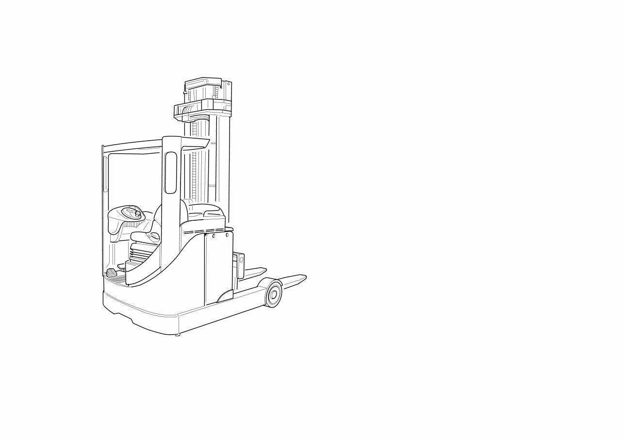
Linde Electric Reach Truck
R 14 / R 14 HD / R 16 / R 16 N
R 16 HD / R 20 / R 20 N
1206 115 804 2501 GB
115-02
Linde - Your Partner
Linde, an enterprise operating
worldwide in the investment
and service sector, is one of the
largest industrial enterprises in
the EC with its four divisions
and over 80 associated com-
panies.
Linde is a leading manufac-
turer of industrial trucks and
hydraulics. It includes seven
manufacturing plants in the
Federal Republic of Germany,
France and Great Britain, as
well as subsidiaries and
branches in all economically
important countries.
Linde industrial trucks enjoy a
worldwide reputation - thanks
to their high quality in engin-
eering, performance and serv-
ice.
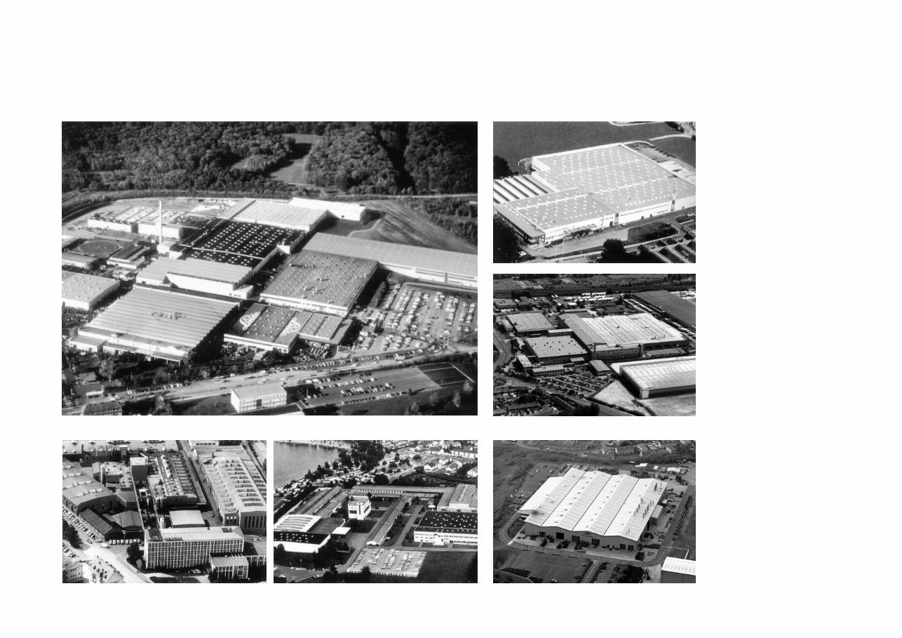
Linde AG Linde Material Handling Division
Werk II, Aschaffenburg-Nilkheim
Werk I, Aschaffenburg
Linde Material Handling (UK) Ltd., Basingstoke
Fenwick-Linde, Châtellerault
Werk III, Kahl am Main
Linde Heavy Truck Division Ltd., Merthyr Tydfil

2
115 804 2501.1206
Description
Your
Linde lift trucks offer the best in economy, safety and driving
convenience. However, preserving the qualities of the truck
for a long and profitable service life, and making full use of
their benefits in operation, relies mainly on the operator.
This Operating Instructions manual tells you all you must know
about starting, running, servicing and maintaining your Linde
lift truck.
Follow the instructions for operating the lift truck and carry out
the maintenance and care prescribed in the maintenance plan
regularly and on time.
To keep your warranty valid and to ensure safety, all mainte-
nance should only be carried out by qualified persons author-
ised by Linde.
Approved applications
Linde trucks are designed for transporting and lifting loads
stated on the load capacity plate within a temperature range
of 40°C down to -10°C standard, or -30°C as an option.
In particular, we refer to the attached booklet (VDMA or BITA
for UK market) concerning the safe operation and accident
prevention for fork lift trucks, to the safety guidelines for gas
vehicles and the regulations for use of the truck on public
roads.
The booklet for users of industrial and rough terrain trucks
(VDMA or BITA for UK market) must be followed under all
circumstances by the operator and service personnel.
The user, and not Linde, is responsible for any accidents aris-
ing from applications not authorised by the manufacturer.
Should you want to use the forklift truck for applications not
covered in these instructions, please contact your local Linde
representative.
No modifications or conversions may be made, or additional
equipment fitted to your fork lift truck, without prior permission
of the manufacturer.
For attachments: the operating instructions supplied by the
attachment manufacturer are applicable.

3
115 804 2501.1206
Description
Technical note
These operating instructions or excerpts thereof may only be
copied, translated or transmitted to third parties after prior
written approval by the manufacturer.
Linde pursues a policy of continuous improvement in design
and manufacture of its products. The illustrations and techni-
cal details referring to design, fittings and engineering of lift
trucks are subject to change or modification as a result of
technological progress by Linde.
Linde is therefore unable to consider any claims based on the
specification, illustrations and descriptions contained in this
Operating Instructions manual.
Please submit all enquiries concerning Linde fork truck or-
ders for spare parts to your local Linde representative, mak-
ing sure to give the correct delivery address.
For repairs use only original Linde spare parts. Only in this
way can it be guaranteed that your Linde fork lift truck main-
tains its original technical standard.
When ordering spare parts, please specify the part number
and state the following truck data.
Lift Truck Type__________________________________
Manufacturer’s Serial No./Year built :_________________
Delivery Date :____________________________________
Please also specify the production number of the mast, when
ordering mast parts.
Mast No :________________________________________
Mast Lift Height :_______________________________mm
When taking over the fork lift truck, transfer the data from the
type plates into this Operating Instructions manual. This infor-
mation can be found on the type plates on the truck. We rec-
ommend that you transfer this information to this manual for
ease of future reference.
Truck takeover
Every Linde lift truck undergoes careful inspection before leav-
ing the factory in order to make sure that it will be in good
condition and fully equipped as ordered when delivered.
Your local Linde representative is under obligation to re-in-
spect the truck before delivery and to hand it over in full work-
ing order.
In order to avoid later complaints and inconvenience to cus-
tomers, you are requested to ascertain that the truck is in
satisfactory condition and fully equipped at the time of deliv-
ery and to acknowledge the correct installation of the truck in
the manufacturers certificate of conformity.
The following technical documents belong to each fork lift truck:
1 Operating Instructions manual
1 EC Certificate of Conformity
The manufacturer certifies that the industrial truck con-
forms to all relevant EC directives.
1 Spare Parts Catalogue
1 Booklet for users of industrial and rough terrain trucks
(VDMA or BITA for UK market)
5
115 804 2501.1206
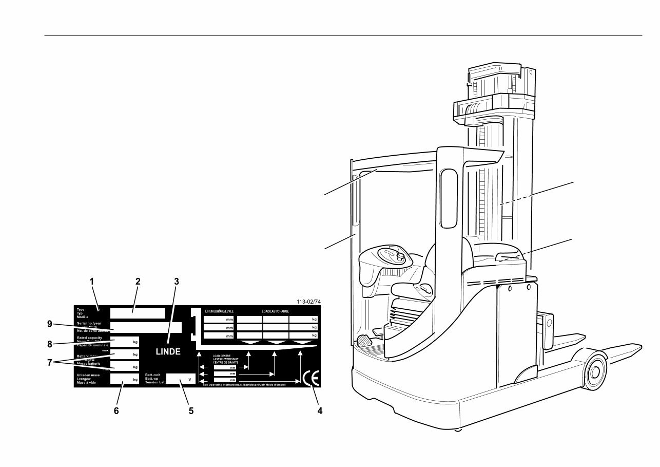
Type plates
1 Truck type/capacity plate
2 Truck type
3 Manufacturer
4 EC symbol
(The symbol certifies that all relevant EC directives and
all applicable guidelines are fulfilled)
5 Battery voltage
6 Unladen mass
7 Battery mass
8 Rated capacity
9 Serial number/year of manufacture
10 Mast number
11 Serial number
12 Attachment capacity plate
}
Stamped
115-03
10
1
12
11
6
115 804 2501.1206
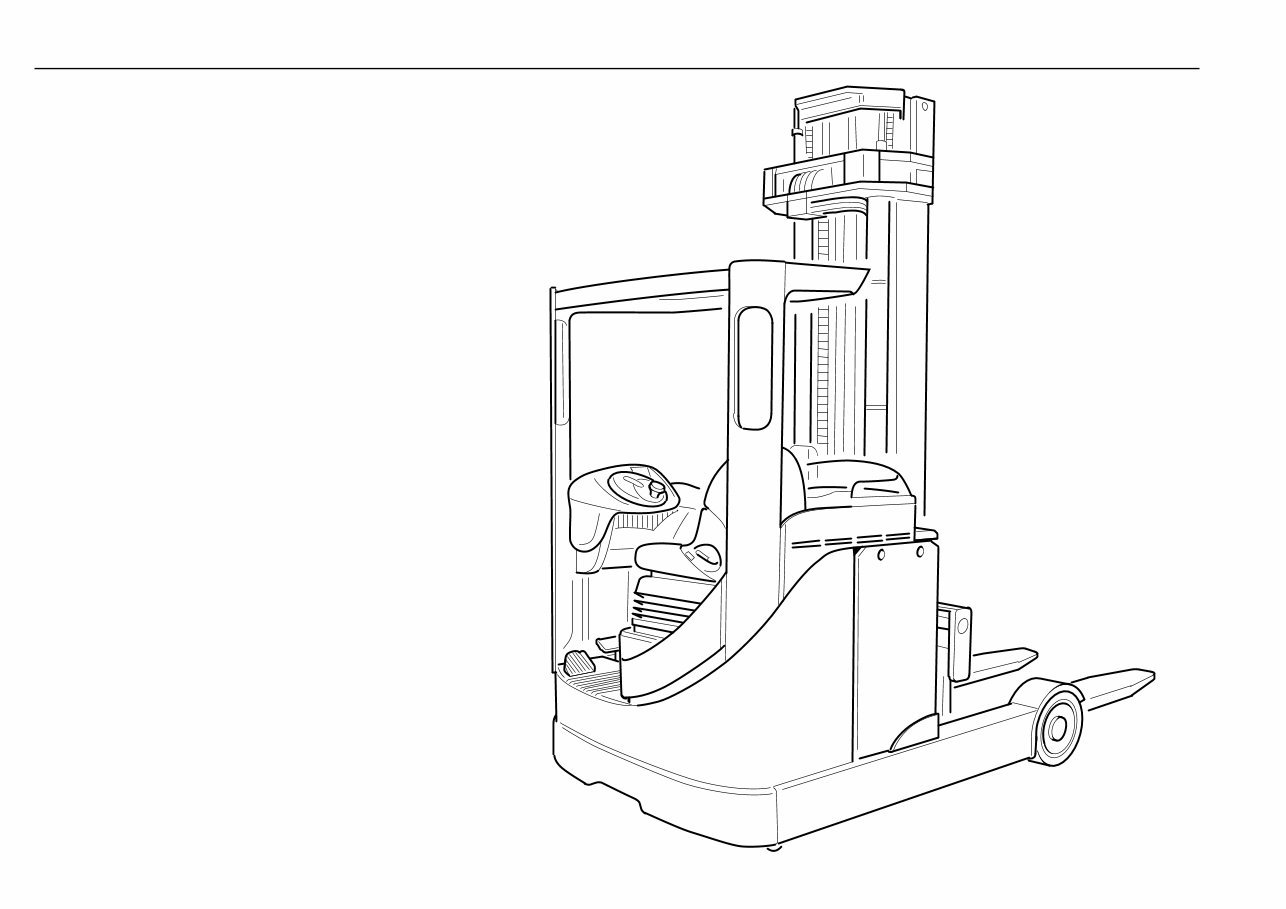
Electric reach truck R 14, R 14 HD, R 16, R 16 N, R 16 HD, R 20, R 20 N
The 115 series of three wheel electric reach trucks fully com-
ply with all relevant EC directives, and have been developed
to suit a wide range of applications.
The main design features result from a thorough analysis of
materials handling requirements and will ensure maximum
productivity.
The operator’s compartment and controls are arranged ac-
cording to the latest ergonomic findings. Each operating func-
tion is tailored to suit the operator both in terms of layout and
ease of operation, thus ensuring safe and fatigue-free opera-
tion.
115-02

7
115 804 2501.1206
Table of contents
Description
Approved applications ............................................ 2
Technical note ........................................................ 3
Truck takeover ........................................................ 3
Type plates .............................................................. 5
Technical data ........................................................ 9
Technical description ............................................. 12
Introduction ............................................................. 12
Operator’s compartment and controls ............. 12
Chassis ............................................................ 12
Drive and transmission .................................... 12
Electrical system ............................................... 12
Steering ............................................................. 12
Mast, hydraulics and reach frame .................... 12
Braking .............................................................. 12
General view of truck .............................................. 13
Operating controls and indicators - dual pedal ..... 14
Operating controls and indicators - single pedal .. 15
Operator's display .................................................. 16
Multi purpose display ........................................ 16
Hour meter ........................................................ 16
Battery discharge indicator ............................... 17
Drive wheel position indicator .......................... 17
Motor brushwear indicators .............................. 17
Over temperature indicators ............................. 18
Interlock warning indicator ................................ 18
Brake fluid level indicator .................................. 18
Service warning indicator ................................. 18
Parking brake warning ...................................... 19
Battery unlocked warning ................................. 19
Slow speed indicator ........................................ 19
Before operation
Safety rules ............................................................. 20
Safety information ................................................... 20
Report of Thorough Examination ........................... 21
Noise emission levels ........................................... 21
Frequency characteristic for human body
vibrations ................................................................ 21
Running-in instructions .......................................... 21
Checks prior to initial operation ............................. 21
Daily checks ........................................................... 21
Open the motor cover ....................................... 22
Removing the floorplate ................................... 22
Opening the top cover ....................................... 22
Checking state of battery charge ...................... 23
Charging the battery ......................................... 23
Connecting the battery to an external charger .. 23
Reaching the battery out ................................... 24
Check the battery condition, electrolyte level
and specific gravity ............................................ 24
Changing the battery (hoist method) ................. 25
Changing the battery (roll on, roll off) ................ 26
Steering column adjustment .............................. 27
Seat adjustments ............................................... 27
Controls and their operation ............................. 28
Interlock switches ............................................. 28
Operation
Driving ..................................................................... 29
Starting on an incline .............................................. 29
Mounting and dismounting the truck ...................... 29
Operating controls - dual pedal ............................. 30
Driving ............................................................... 30
Travel with the forks trailing .............................. 30
Travel with the forks leading ............................. 30
Change the direction of travel ........................... 30
Operating controls - single pedal .......................... 31
Driving ............................................................... 31
Travel with the forks trailing .............................. 31
Travel with the forks leading ............................. 31
Change direction of travel ................................. 31
Braking - dual pedal ............................................... 32
Brakes ............................................................... 32
Regenerative traction brake ............................. 32
Hydraulic footbrake ........................................... 32
Parking brake .................................................... 32
Engaging the parking brake ............................. 32
Releasing the parking brake ............................ 32
Braking - single pedal ............................................ 33
Brakes ............................................................... 33
Regenerative traction brake ............................. 33
Hydraulic footbrake ........................................... 33
Parking brake .................................................... 33
Engaging the parking brake ............................. 33
Releasing the parking brake ............................ 33
Steering ................................................................... 34
Turning radius ........................................................ 34
Operation of mast and attachments
(with Linde Load Control) ........................................ 35
Raising the fork carriage ................................... 35
Lowering the fork carriage ................................. 35
Reaching the mast out ...................................... 35
Reaching the mast back .................................... 35
Tilting the fork carriage forward ......................... 35
Tilting the fork carriage back ............................. 35
Operating the sideshift ...................................... 35
Operating the attachments ................................ 35
Operation of mast and attachments
(four lever control) ................................................... 36
Raising the fork carriage ................................... 36
Lowering the fork carriage ................................. 36
Reaching the mast out ...................................... 36
Reaching the mast back .................................... 36
Tilting the fork carriage forward ......................... 36
Tilting the fork carriage back ............................. 36
Operating the sideshift ...................................... 36
Operating the attachments ................................ 36
Operation of horn .................................................... 37
Emergency isolator ................................................. 37
Load capacity example ........................................... 38
Positioning the forks ............................................... 39
Destacking a load ................................................... 39
Transporting a load ................................................. 41
Stacking a load ........................................................ 41
Before leaving the truck .......................................... 41
Fuses (main circuit) ............................................... 42

8
115 804 2501.1206
Table of contents (continued)
Fuses (ancillary circuits) ........................................ 42
Slinging the truck .................................................... 43
Jack locations when changing wheels .................. 43
Emergency lower .................................................... 44
Emergency steering and parking brake release ... 44
Towing procedure ................................................... 45
Cold store cab ........................................................ 46
Side guidance for drive in racking .......................... 48
360° steering .......................................................... 48
Lift Height Indicator (LHI) ........................................ 49
Height preselector (LPS mode) ............................. 53
Height preselector (LPS0 mode) ........................... 57
Operator code entry ................................................ 60
Data logger ............................................................. 63
Closed circuit television ......................................... 63
Maintenance
Maintenance and safety guidelines ....................... 64
General information .......................................... 64
Handling lubricants .......................................... 64
Avoiding accidents ............................................ 65
Safety guidelines .............................................. 65
Measures before taking the truck out of operation 66
Putting the truck back into operation ...................... 66
Work on the mast and the reach frame part of
the truck .................................................................. 67
Mast removal .......................................................... 67
Securing the reach frame against
reaching in or out .................................................... 67
The mast ................................................................. 67
Securing the mast .................................................. 67
Inspection and maintenance after the first 50
hours of operation .................................................. 68
Lubrication intervals ............................................... 68
Inspection and maintenance schedule ................. 69
Inspection and maintenace as required
Clean the truck ........................................................ 71
Lubricate the lift chains and mast channels .......... 71
Adjust the lift chains ............................................... 72
Renew the motor brushes ..................................... 72
Renew the hydraulic hoses ................................... 73
Check drive wheel nuts. ......................................... 73
Replace the battery trolley slides ........................... 73
1000 Hour inspection and maintenance
(250 hours cold store)
Check and adjust the parking brake ...................... 74
Check the hydraulic hoses and pipes for damage 74
Check the mast and lift chains for condition and
security .................................................................... 74
Lubricate the mast, mast rollers, lift chains and
chain pulleys ........................................................... 75
Lubricate the mast hose pulley assemblies ......... 75
Lubricate the reach channels and rollers .............. 76
Check the condition of the wheels and tyres ......... 76
Check and lubricate the battery trolley slides and
associated mechanism ......................................... 77
Check the condition and security of
motor and battery connectors and cables ............. 77
Check the hydraulic oil level ................................... 77
Lubricate the fork carriage and sideshift
slider pad ................................................................ 78
Check condition of side guide rollers .................... 78
Lubricate cold store cab hinges and door latch .... 78
2000 Hour inspection and maintenance
(1000 hours cold store)
Visual check of motor brushes .............................. 79
Check the brake fluid level ..................................... 79
Check the traction motor brake band and load
wheel shoes for wear and adjustment .................. 80
Renew the hydraulic tank breather filter ................. 80
Check the reach carriage rollers, adjust
if required ................................................................ 80
5000 Hour inspection and maintenance
(2500 hours cold store)
Check condition of brake pipes ............................. 81
Grease the load wheel bearings ........................... 81
Change the hydraulic fluid ...................................... 82
Renew the hydraulic suction line filter ................... 83
10000 Hour or 5 year
inspection and maintenance
(5000 hours or 30 months cold store)
Change the brake fluid ........................................... 84
Inspection and maintenance data ................................. 85
Recommended lubricants ............................................. 86
Hydraulic oil ............................................................ 86
Multipurpose grease .............................................. 86
Gear oil ................................................................... 86
General purpose oil ............................................... 86
Chain Spray ............................................................ 86
Brake fluid ............................................................... 86
Troubleshooting guide (hydraulic system) .................... 87
Hydraulic system piping ................................................. 88
Circuit diagram ............................................................... 89
Circuit diagram - lighting ................................................ 94
Circuit diagram - CCTV .................................................. 95
Circuit diagram - cabin ................................................... 96
Index .......................................................................... 99
9
115 804 2501.1206
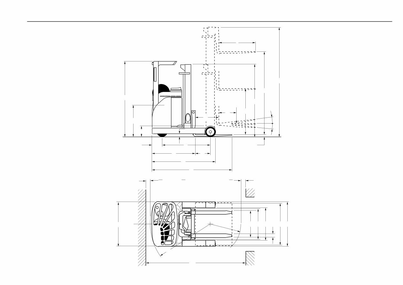
Technical data Description
m /m
1 2
Q
218 - 1250 wide
224 - 1080 wide
e
a
2
a
2
a
2
= 100mm
b
5
b
2
b
11
b
4
b
3
A
st
W
a
b
10
b
1
y
l
2
x
l
7
l
1
h
4
h
3
h
1
h
2
a
b
h
6
h
7
h
8
l
s
c
l
4

10
115 804 2501.1206
Technical data Description
1.1 Manufacturer Linde Linde Linde Linde Linde Linde Linde
1.2 Model designation R 14 R 16 R 16 N R 16 HD R 20 R 14 HD R 20 N
1.3 Power unit: battery, diesel, petrol, LP gas, mains power Battery Battery Battery Battery Battery Battery Battery
1.4 Operation: Manual, pedestrian, stand-on, seated, order picker Seated Seated Seated Seated Seated Seated Seated
1.5 Load capacity 1.4
3)
(t) 1.6
3)
1.6
3)
1.6
3)
2.0
3)
1.4
3)
2.0
3)
1.6 Load centre 600/500 (mm) 600/500 600/500 600/500 600/500 600/500 600/500
1.8 Axle centre to fork face 311 (mm) 416 346 380 475 270 385
1.9 Wheelbase
2.1 Service weight
2.3 Axle load without load, front (drive)/rear (load)
2.4 Axle load, fork outreached with load, front (drive)/rear (load)
2.5 Axle load, fork retracted with load, front (drive)/rear (load)
1 275 (mm) 1 385 1 385 1 385 1 520 1 275 1 520
2 890
4)
kg 2 940
4)
2 820
4)
3 070
4)
3 260
4)
3 020
4)
3 100
4)
1 800/1 090
4)
kg 1 900.1 040
4)
1 760.1 060
4)
1 995/1 075
4)
2 120/1 140
4)
2 830/1 190
4)
1 840/1 260
4)
520/3 770
4)
kg 530/4 010
4)
465/3 955
4)
420/4 250
4)
630/4 630
4)
500/3 920
4)
600/4 500
4)
1 485/2 805
4)
kg 1 690/2 850
4)
1 460/2 960
4)
1 740/2 930
4)
1 960/3 300
4)
1 480/2 940
4)
1 555/3 545
4)
3.1 Tyres, front (drive)/rear (load) C = cushion rubber, P = polyurethane P/P P/P P/P P/P P/P P/P P/P
3.2 Tyre size, front (drive) wheel
3.3 Tyre size, rear (load) wheel
3.5 Wheels, number front (drive)/rear (load)
330 x 135 mm 330 x 135 330 x 135 330 x 135 330 x 135 330 x 135 330 x 135
285 x 100 mm 285 x 100 285 x 100 285 x 100 350 x 100 285 x 100 350 x 100
1x/2 1x/2 1x/2 1x/2 1x/2 1x/2 1x/2
3.6 Track width, front (drive)
3.7 Track width, rear (load)
4.1 Mast/fork carriage tilt, forward/backward
0 mm 0 0 0 0 0 0
1 150 mm 1 150 980 1 150 1 150 1 150 980
2/4 a/b (°) 2/4 2/4 2/4 2/4 2/4 2/4
4.2 Height of mast, lowered
4.3 Free lift
4.4 Lift
4.5 Height of mast, extended
4.7 Height of overhead guard (cabin)
4.10 Height of reach legs
4.19 Overall length
4.20 Length to fork face
4.21 Overall width
4.22 Fork dimensions
2 110 h
1
(mm) 2 110 2 110 2 930 2 476 2 930 2 476
1 261 h
2
(mm) 1 261 1 261 2 081 1 627 2 081 1 627
4 655
1)
h
3
(mm) 4 655
1)
4 655
1)
6 355
1)
4 655
1)
6 355
1)
4 655
1)
5 395 h
4
(mm) 5 395 5 395 7 139 5 395 7 139 5 395
2 110 h
6
(mm) 2 110 2 110 2 110 2 110 2 110 2 110
4.8 Height of seat, minimum/maximum 940/1 030 h
7
(mm) 940/1 030 940/1 030 940/1 030 940/1 030 940/1 030 940/1 030
310 h
8
(mm) 310 310 310 373 310 373
2 184 l
1
(mm) 2 189 2 265 2 225 2 261 2 225 2 261
1 184 l
2
(mm) 1 189 1 265 1 225 1 261
5)
1 225 1 361
1 234/1 250 b /b
1 2
(mm) 1 234/1 250 1 054/1 080 1 234/1 250 1 234/1 250
6)
1 234/1 250
6)
1 054/1 080
40 x 80 x 1 000 s/e/l (mm) 45 x 100 x 1 000 45 x 100 x 1 000 45 x 100 x 1 000 45 x 100 x 1 000 45 x 100 x 1 000 45 x 100 x 1 000
4.23 Fork carriage to DIN 15173, class/form A,B 2A 2A 2A 2A 2A 2A 2A
4.24 Width of fork carriage
4.25 Fork spread, minimum/maximum
830 b
3
(mm) 830 830 830 830 830 830
296/690 b
5
(mm) 316/710 316/520 316/710 316/710 316/710 316/520
4.26 Width between reach legs 922 b
4
(mm) 922 752 922 922 922 752
4.28 Reach travel 496 l
4
(mm) 606 536 570 695 460 608
4.32 Ground clearance, centre of wheelbase 75 m
2
(mm) 75 75 75 75 75 75
4.33 Aisle width with pallet 1000 x 1200 across forks 2 655 (2 430)
9)
Ast (mm) 2 675(2 425)
9)
2 710 (2 475)
9)
2 705 (2 460)
9)
2 770 (2 500)
5) 9)
2 685 (2 470)
9)
2 810 (2 565)
5) 9)
4.34 Aisle width with pallet 1000 x 1200 along forks
4.35 Turning radius
4.37 Length of chassis
5.2 Lifting speed, with/without load
5.3 Lowering speed, with/without load
5.7 Climbing ability, with/without load, 30 minute rating
Characteristics Weights Wheels and tyres Dimensions Performance Drive Other
2 715 (2 630)
9)
Ast (mm) 2 720 (2 625)
9)
2 765(2 675)
9)
2 800 (2 660)
9)
2 805 (2 700)
5) 9)
2 750 (2 670)
9)
2 860 (2 765)
5) 9)
1 540 W
a
(mm) 1 640 1 620 1 640 1 775 1 540 1 750
1 638 l
7
(mm) 1 748 1 754 1 748 1 911 1 638 1 921
5.1 Travel speed, with/without load
12/12.5
4) 10)
km/h 12/12.5
4)10)
12/12.5
4)10)
12/12.5
4)10)
12/12.5
4)10)
12/12.5
4)10)
12/12.5
4)10)
0.34/0.6
4)
m/s 0.34/0.6
4)
0.34/0.6
4)
0.3/0.48
4)
0.3/0.48
4)
0.32/0.49
4)
0.3/0.48
4)
0.55/0.45
4)
m/s 0.55/0.45
4)
0.55/0.45
4)
0.55/0.4
4)
0.55/0.4
4)
0.55/0.45
4)
0.55/0.4
4)
0.15/0.15
4)
m/s 0.15/0.15
4)
0.15/0.15
4)
0.15/0.15
4)
0.15/0.15
4)
0.15/0.15
4)
0.15/0.15
4)
5.4 Reach speed, with/without load
4.5/8.2 % 4.7/8.2 4.3/8 3.9/7.1 3.9/7.1 4.5/8.2 3.9/7.2
5.8 Climbing ability, with/without load, 5 minute rating 10/10 % 10/10 10/10 10/10 10/10 10/10 10/10
5.9 Acceleration time, with/without load 5.5/4.8
10)
s 5.5/4.8
10)
5.5/4.8
10)
5.8/5
10)
5.8/5 5.8/5
10)
5.8/5
5.10 Service brake Hydraulic/electric Hydraulic/electric Hydraulic/electric Hydraulic/electric Hydraulic/electric Hydraulic/electric Hydraulic/electric
6.1 Drive motor, 60 minute rating 5.4 kW 5.4 5.4 5.4 5.4 5.4 5.4
6.3 Battery according to DIN 43531/35/36 A, B, C, no DIN 43531C DIN 43531C DIN 43531C DIN 43531C DIN 43531C DIN 43531C DIN 43531C
6.4 Battery voltage/rated capacity (5h) 48/420
2)
V/Ah 48/420
2)
48/420
2)
48/420
2)
48/560
2)
48/420
2)
48/560
2)
6.5 Battery weight (±5%)
6.6 Power consumption according to VDI cycle
8.1 Type of drive control
8.2 Working pressure for attachments
8.3 Oil flow for attachments
8.4 Noise level at operator's ear
750 kg
kW/h
750 746 750 939 750 937
7) 7) 7) 7) 7) 7) 7)
Electronic/stepless Electronic/stepless Electronic/stepless Electronic/stepless Electronic/stepless Electronic/stepless Electronic/stepless
200 bar 200 200 200 200 200 200
6.5 l/min 6.5 6.5 6.5 6.5 6.5 6.5
63
8)
dB (A) 63
8)
63
8)
63
8)
64 63 64
8)
6.2 Lift motor, 15% rating 12 kW 12 12 12 12 12 12
4.31 Ground clearance, mast 75 m
1
(mm) 75 75 75 75 75 75
/ /
8) 8)
NOTES:
1. For all other heights, see
table.
2. Alternative batteries
increase length to fork
face and 90° stacking
aisle widths.
3. Capacity may be reduced
for high lifts.
4. Traction, lift, lower and
reach speeds and weights
may vary with alternative
lift heights.
5. Lift heights 6 400 mm and
above increase length to
fork face and 90° stacking
aisle widths by 27 mm on
R 20 and R 20 N
6. Alternative widths over
reach legs of 1 400 mm
or 1 600 mm are available
for R 20
7. Refer to manufacturer for
figures.
8. Figure shown without cab;
66dB (A) when cab fitted.
9. Figures shown in brackets
are for intrusive stacking.
10. Reduced speed and
acceleration on request.
You're Reading a Preview
What's Included?
 Lifetime Access
Fast Download Speeds
Online & Offline Access
Access PDF Contents & Bookmarks
Full Search Facility
Print one or all pages of your manual
$32.99
Linde Electric Reach Truck Type 115: R14, R14HD, R16, R16HD, R16N, R20, R20N Operating Instructions (User Manual)
Viewed 77 Times Today

What's Included?
Lifetime Access
Fast Download Speeds
Online & Offline Access
Access PDF Contents & Bookmarks
Full Search Facility
Print one or all pages of your manual
$32.99

Secure transaction
What's Included?
Lifetime Access
Fast Download Speeds
Online & Offline Access
Access PDF Contents & Bookmarks
Full Search Facility
Print one or all pages of your manual
Description
These factory manuals for Linde Electric Reach Truck Type 115 are essential resources for both professional mechanics and DIY enthusiasts. The manuals contain high-quality images, circuit diagrams, and detailed instructions to assist with the operation and repair of the covered models, including R14, R14HD, R16, R16HD, R16N, R20, and R20N.
- Format: .PDF, 102 Pages
- Language: English
The manuals cover a wide range of technical information, including but not limited to:
- Description
- Approved applications
- Technical note
- Truck takeover
- Type plates
- Technical data
- Technical description
- Introduction
- Operators compartment and controls
- Chassis
- Drive and transmission
- Electrical system
- Steering
- Mast, hydraulics, and reach frame
- Braking
- General view of truck
- Operating controls and indicators - dual pedal
- Operating controls and indicators - single pedal
- Operator's display
- Multi-purpose display
- Hour meter
- Battery discharge indicator
- Drive wheel position indicator
- Motor brush wear indicators
- Over-temperature indicators
- Interlock warning indicator
- Brake fluid level indicator
- Service warning indicator
- Parking brake warning
- Battery unlocked warning
- Slow speed indicator


