

© BT
Repair Manual en
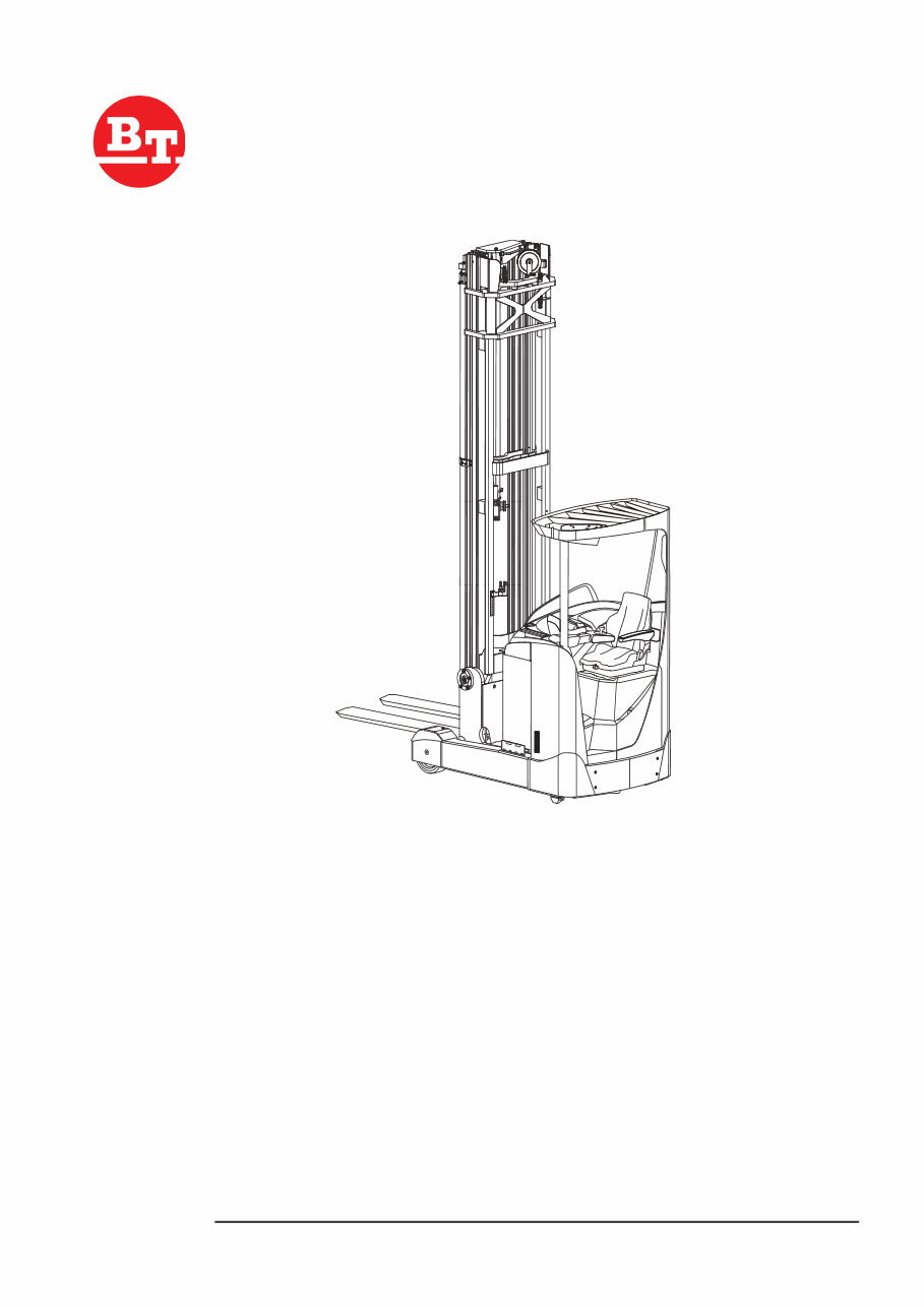
RRE140/160/180/200/250
Valid from serial number: 6051502
Order number: 261828-040
Issued: 2008-08-21 ITS

© BT Repair Manual RRE140/160/180/200/250
Document revisions:
This manual covers following truck models:
Issue date Publication
No.
Changes
2008-08-21 261828-040 Completely new issue.
T-code Model Serial number
815 RRE140, RRE140C, (RRE140CC),
RRE140E,RRE140EC, (RRE140ECC),
RRE160, RRE160C, (RRE160CC)
RRE160E, RRE160EC, (RRE160ECC)
6051502-
816 RRE180, RRE180C, (RRE180CC),
RRE180E, RRE180EC, (RRE180ECC),
RRE200, RRE200C, (RRE200CC),
RRE200E, RRE200EC, (RRE200ECC),
RRE250, RRE250C, (RRE250CC),
RRE250E, RRE250EC, (RRE250ECC)
6051502-

Contents
Publication No. Date Valid from serial number T-code
261828-040 2008-08-21 6051502 815, 816
© BT Repair Manual RRE140/160/180/200/250 1 – 1
1 – Contents
1 – Contents ............................................................................................. 1-1
2 – General introduction ......................................................................... 2-1
2.1 How to use the manual................................................................... 2-1
2.2 Warning symbols ........................................................................... 2-2
2.3 Pictograms ..................................................................................... 2-2
3 – General safety rules .......................................................................... 3-1
3.1 Safety while working ...................................................................... 3-1
3.2 Electrical system ............................................................................ 3-2
3.3 Safe lifting ...................................................................................... 3-3
4 – Functions and parameters ................................................................ 4-1
4.1 Chassis 0000 ................................................................................. 4-1
4.1.1 Driver protection (0840) ................................................... 4-1
Tilt stops .......................................................................... 4-1
Overhead guard ............................................................... 4-2
4.2 Motors 1000 ................................................................................... 4-3
4.2.1 General ............................................................................ 4-3
4.2.2 Electric pump motor (1710) ............................................. 4-3
General ............................................................................ 4-3
Design ............................................................................. 4-3
4.2.3 Electric steering motor (1730) ......................................... 4-4
General ............................................................................ 4-4
Design ............................................................................. 4-4
4.2.4 Fan motor/fan (1740) ....................................................... 4-5
4.2.5 Electric drive motor (1760) .............................................. 4-6
General ............................................................................ 4-6
Design ............................................................................. 4-6
4.3 Drive gear – 2000........................................................................... 4-7
4.3.1 General ............................................................................ 4-7
4.3.2 Design ............................................................................. 4-8
4.4 Brake system 3100 ........................................................................ 4-9
4.4.1 General ............................................................................ 4-9
Travel brake ..................................................................... 4-9
Parking brake .................................................................. 4-9
Emergency brake ............................................................ 4-9
4.4.2 Drive motor brake (travel brake) .................................... 4-10
Accelerator released ...................................................... 4-10
Changing the direction of travel ..................................... 4-10
4.4.3 Multiple disc brake, support arm (travel brake) ............. 4-11
General .......................................................................... 4-11
Design ........................................................................... 4-11
4.4.4 Disc brake on the drive motor (parking brake) .............. 4-12
General .......................................................................... 4-12
Design ........................................................................... 4-12
4.5 Steering system 4000 .................................................................. 4-13
4.5.1 General .......................................................................... 4-13
Design ........................................................................... 4-13
4.6 Operator compartment ................................................................. 4-14
4.6.1 Truck control, overview .................................................. 4-14

1 – 2 Repair Manual RRE140/160/180/200/250 © BT
Contents
T-code Valid from serial number Date Publication No.
815, 816 6051502 2008-08-21 261828-040
Right-hand control panel, single control ........................ 4-14
Right-hand control panel, multi-control .......................... 4-14
Emergency switch off .................................................... 4-14
Steering module ............................................................ 4-15
Pedals ............................................................................ 4-16
4.6.2 Single control ................................................................. 4-17
4.6.3 Multi-control ................................................................... 4-18
4.6.4 Central Information Display – CID ................................. 4-19
CID LED symbols .......................................................... 4-19
CID information symbols in the display area ................. 4-20
CID disable indications in the display area .................... 4-21
CID service symbols in the display area ........................ 4-22
Driver parameter symbols ............................................. 4-23
Navigation ...................................................................... 4-24
4.6.5 Load Information Display – LID (option) ........................ 4-27
LID LED symbols ........................................................... 4-27
LID symbols in the display area ..................................... 4-28
4.7 Operation and connection sequences.......................................... 4-29
4.8 Functions ..................................................................................... 4-43
4.8.1 General overview ........................................................... 4-43
Key ................................................................................ 4-43
Components .................................................................. 4-43
4.8.2 MCU – Main Control Unit ............................................... 4-44
General .......................................................................... 4-44
System communication ................................................. 4-44
4.8.3 ACT/ACH transistor regulators ...................................... 4-44
General .......................................................................... 4-45
4.8.4 Start-up .......................................................................... 4-45
4.8.5 Shutdown ....................................................................... 4-45
4.8.6 Driving ........................................................................... 4-46
Introduction .................................................................... 4-46
Acceleration and speed reduction ................................. 4-46
Reversing ...................................................................... 4-47
Brake ............................................................................. 4-47
Travel speed .................................................................. 4-48
4.8.7 Steering ......................................................................... 4-49
Steering position check ................................................. 4-49
Steering speed .............................................................. 4-49
Steering reference ......................................................... 4-50
Travel speed limitation ................................................... 4-50
Compass card ............................................................... 4-50
4.8.8 Hydraulic system ........................................................... 4-51
Definitions ...................................................................... 4-51
Controls ......................................................................... 4-51
Lift .................................................................................. 4-51
Reach movement .......................................................... 4-52
Lift height limitation ........................................................ 4-52
Maximum height limitation ............................................. 4-52
Auxiliary/Extra functions (option) ................................... 4-53
4.9 Height preselector, description of function ................................... 4-54
4.9.1 Using the height preselector .......................................... 4-54
4.9.2 Symbols ......................................................................... 4-54
4.9.3 Buzzer ........................................................................... 4-54
4.9.4 Height preselector levels ............................................... 4-55
4.9.5 Level selection ............................................................... 4-55
4.9.6 Height programming ...................................................... 4-56

Contents
Publication No. Date Valid from serial number T-code
261828-040 2008-08-21 6051502 815, 816
© BT Repair Manual RRE140/160/180/200/250 1 – 3
4.9.7 Height preselector and TruckCom ................................. 4-57
4.9.8 Lift/lowering movement .................................................. 4-57
4.10 Hydraulic system 6000 ................................................................. 4-58
4.10.1 General .......................................................................... 4-58
4.10.2 Tank ............................................................................... 4-58
4.10.3 Filter ............................................................................... 4-58
Return filter .................................................................... 4-58
Dehumidification filter .................................................... 4-58
4.10.4 Hydraulic pump .............................................................. 4-59
4.10.5 Valve block .................................................................... 4-59
Main valve block ............................................................ 4-59
Other valve blocks ......................................................... 4-60
4.10.6 Cylinders ........................................................................ 4-61
Main lift cylinder ............................................................. 4-61
Free lift cylinder ............................................................. 4-61
Cylinders for the reach movement, cabin tilt, sideshift and fork
tilt ................................................................................... 4-61
4.10.7 Lift and lowering function ............................................... 4-62
Lifting and lowering of free lift ........................................ 4-62
Transition from free lift to main lift ................................. 4-62
Lifting and lowering of main lift ...................................... 4-62
Reach movement, in and out ......................................... 4-62
Simultaneous operation of mast lift and reach movement . 4-
63
4.10.8 Extra functions ............................................................... 4-63
4.10.9 Cabin tilt (RRE Ergo) ..................................................... 4-63
Hydraulic priority system ............................................... 4-63
Cabin tilt (RRE Ergo) during servicing ........................... 4-64
Cabin tilt in the event of hydraulic or electrical power loss 4-
64
4.11 Mast 7000 .................................................................................... 4-65
4.11.1 Mast and reach carriage ................................................ 4-65
4.12 Lifting devices .............................................................................. 4-66
4.12.1 Fork extensions ............................................................. 4-66
4.12.2 Telescopic forks ............................................................. 4-66
4.13 Parameters .................................................................................. 4-68
4.13.1 General .......................................................................... 4-68
4.13.2 Displaying/changing parameters ................................... 4-69
4.13.3 Parameters .................................................................... 4-69
Operator parameters, overview ..................................... 4-69
Service parameters, overview ....................................... 4-70
Factory parameters, overview ....................................... 4-75
Calibration parameters, overview .................................. 4-77
5 – Installation ......................................................................................... 5-1
5.1 Transporting the truck .................................................................... 5-1
Method 1 .......................................................................... 5-1
Method 2 .......................................................................... 5-1
5.2 Initial operation............................................................................... 5-2
5.2.1 Placing the battery ........................................................... 5-2
5.2.2 Parameters on initial operation ........................................ 5-3
Battery ............................................................................. 5-3
Load indicator .................................................................. 5-3
Ergo cabin ....................................................................... 5-3
Cold store cabin ............................................................... 5-4

1 – 4 Repair Manual RRE140/160/180/200/250 © BT
Contents
T-code Valid from serial number Date Publication No.
815, 816 6051502 2008-08-21 261828-040
5.2.3 Parameters for optional equipment ................................. 5-4
Height measurement (option) .......................................... 5-4
Travel speed limitation, height-dependent ....................... 5-4
Travel speed limitation, reach movement dependent ...... 5-4
Travel speed limitation, parameter-dependent ................ 5-5
Collision sensor (BT) ....................................................... 5-5
5.2.4 Mast, fitting ...................................................................... 5-5
6 – Maintenance ....................................................................................... 6-1
6.1 Introduction, maintenance.............................................................. 6-1
6.2 Periodic maintenance .................................................................... 6-2
6.2.1 Every 500 B-hours/180 days ........................................... 6-2
6.2.2 Every 1000 B-hours/360 days ......................................... 6-4
6.2.3 Every 2000 B-hours/720 days ......................................... 6-9
6.2.4 Every 3000 B-hours/1080 days ....................................... 6-9
6.2.5 Every 5000 B-hours/1800 days ..................................... 6-11
6.2.6 Annual status inspection ................................................ 6-11
6.3 Maintenance instructions ............................................................. 6-12
6.3.1 Cleaning and washing ................................................... 6-12
High-pressure washers .................................................. 6-12
Degreasing agents ........................................................ 6-12
Cleaning the exterior ..................................................... 6-12
Cleaning the chain ......................................................... 6-13
Cleaning the motor compartment .................................. 6-13
Electrical components ................................................... 6-13
7 – Troubleshooting ................................................................................ 7-1
7.0.1 Error log menu ................................................................. 7-1
Error information menu .................................................... 7-1
7.1 Service diagnostics menu .............................................................. 7-2
7.1.1 General ............................................................................ 7-2
7.1.2 Diagnostics states ........................................................... 7-3
State 1 – Voltage from levers .......................................... 7-3
State 2 – Digital signals from truck controls to MCU ....... 7-4
State 3 – Voltages to MCU .............................................. 7-5
State 4 – Digital input signals to MCU ............................. 7-6
State 5 – Digital output signals from MCU ....................... 7-7
State 6 – PWM outputs from MCU .................................. 7-8
State 7 – FCU (not used) ................................................. 7-8
State 8 – FCU (not used) ................................................. 7-8
State 9 – GFU (not used) ................................................ 7-8
State 10 – GFU (not used) .............................................. 7-8
State 11 – Temperature signals ...................................... 7-9
State 12 – Voltage levels ................................................. 7-9
State 13 – Travel information ........................................ 7-10
State 14 Steering information ........................................ 7-11
State 15 – Lift/lowering information ............................... 7-12
State 16 – Reach movement ......................................... 7-13
State 17 – Hydraulic information ................................... 7-14
7.2 Warning and error codes.............................................................. 7-15
Abbreviations used in this section ................................. 7-15
Error code structure ....................................................... 7-15
7.2.1 Error codes ................................................................... 7-17
7.3 ACT/ACH transistor regulators .................................................... 7-34
7.3.1 Cable connections and pole bolts .................................. 7-34

Contents
Publication No. Date Valid from serial number T-code
261828-040 2008-08-21 6051502 815, 816
© BT Repair Manual RRE140/160/180/200/250 1 – 5
7.3.2 Connections on the MCU .............................................. 7-36
7.4 Symptom tables ........................................................................... 7-38
7.4.1 Brake ............................................................................. 7-38
7.4.2 Telescopic forks ............................................................. 7-39
8 – Frame/Chassis 0000 .......................................................................... 8-1
8.1 General .......................................................................................... 8-1
8.2 Motor hood (0340).......................................................................... 8-1
8.2.1 Opening the motor compartment ..................................... 8-1
RRE 160-RRE 250 .......................................................... 8-1
8.3 Operator cabin (0500) .................................................................... 8-2
Cabin tilting RRE 160-250 Ergo ...................................... 8-2
8.4 Operator compartment (0600)........................................................ 8-3
8.4.1 Internal fittings (0680) ...................................................... 8-3
8.5 Safety equipment (0800) ................................................................ 8-4
8.5.1 Checking the overhead guard (0810) .............................. 8-4
8.5.2 Adjusting the tilt stops (0840) .......................................... 8-5
9 – Motors 1000 ........................................................................................ 9-1
9.1 Motor sensors ................................................................................ 9-1
9.1.1 Temperature sensor ........................................................ 9-1
Retrofitting of external temperature sensor ..................... 9-1
9.1.2 Replacing the motor speed sensor .................................. 9-2
9.2 Pump motor (1710) ........................................................................ 9-3
9.2.1 General ............................................................................ 9-3
The pump motor dismantled ............................................ 9-3
9.2.2 Replacing the bearing on the pump motor ...................... 9-4
Dismantling the pump motor ............................................ 9-4
Assembling the pump motor ............................................ 9-6
9.3 Steering motor and steering unit (1730) ......................................... 9-7
9.3.1 General ............................................................................ 9-7
9.3.2 Layout of the flange holes ............................................... 9-7
9.3.3 Removing the steering motor from the truck ................... 9-8
9.3.4 Placing the steering motor in the truck ............................ 9-8
9.4 Fan motor/fan (1740) ..................................................................... 9-9
9.4.1 General ............................................................................ 9-9
9.4.2 Replacing the frequency converter cooling fan ............... 9-9
Standard truck ................................................................. 9-9
Ergotruck ......................................................................... 9-9
9.4.3 Replacing the motor compartment cooling fan .............. 9-11
9.5 Drive motor (1760) ....................................................................... 9-12
9.5.1 General .......................................................................... 9-12
The drive motor dismantled ........................................... 9-12
9.5.2 Removing the drive motor from the truck ...................... 9-13
9.5.3 Dismantling the drive motor ........................................... 9-15
9.5.4 Cleaning ........................................................................ 9-16
9.5.5 Assembling the drive motor ........................................... 9-17
9.5.6 Fitting the drive motor to the truck ................................. 9-19
10 – Drive gear 2000 .............................................................................. 10-1
10.1 General ........................................................................................ 10-1
10.1.1 Leakage from the bottom cap ........................................ 10-1
10.1.2 Replacing the drive gear ................................................ 10-2
Special tools .................................................................. 10-2

1 – 6 Repair Manual RRE140/160/180/200/250 © BT
Contents
T-code Valid from serial number Date Publication No.
815, 816 6051502 2008-08-21 261828-040
Exposing the drive gear ................................................. 10-2
Removing a drive motor from the truck ......................... 10-2
Removing a steering motor from the truck .................... 10-2
Removing the drive gear from the truck ........................ 10-3
10.1.3 Replacing the pinion gear, input shaft ........................... 10-5
Remove the pinion gear ................................................ 10-5
Placing a new ball bearing ............................................. 10-6
Fitting the sealing ring ................................................... 10-6
Inserting the pinion gear in the drive gear ..................... 10-6
10.1.4 Placing the drive gear in the truck ................................. 10-7
Placing the steering motor in the truck .......................... 10-8
Placing the drive motor in the truck ............................... 10-8
10.1.5 Refitting ......................................................................... 10-8
11 – Brake and wheel 3000 ................................................................... 11-1
11.1 Travel brake system (3100) ......................................................... 11-1
11.1.1 Removing the support arm's multiple disc brake ........... 11-1
11.1.2 Dismantling the multiple disc brake ............................... 11-1
Inspection ...................................................................... 11-2
Adjusting play ................................................................ 11-2
Assembling the multiple disc brake ............................... 11-3
11.1.3 Placing the multiple disc brake in the truck ................... 11-3
11.2 Parking brake (3300) ................................................................... 11-4
11.2.1 General .......................................................................... 11-4
11.2.2 Emergency release of the parking brake ....................... 11-5
11.2.3 Checking the brake force ............................................... 11-5
11.2.4 Removing the parking brake from the truck ................... 11-6
Dismantling and checking wear ..................................... 11-6
Assembling the parking brake ....................................... 11-7
Adjusting play ................................................................ 11-7
11.2.5 Placing the parking brake in the truck ........................... 11-8
11.3 Drive wheel (3530) ....................................................................... 11-9
11.3.1 General .......................................................................... 11-9
11.3.2 Removing the drive wheel from the truck ...................... 11-9
11.3.3 Placing the drive wheel on the truck .............................. 11-9
11.4 Wheel bolt (3530) ....................................................................... 11-10
General ........................................................................ 11-10
11.4.1 Replacing wheel bolts .................................................. 11-10
11.5 Support arm wheel (3550).......................................................... 11-11
11.5.1 Removing the support arm wheel from the truck ......... 11-11
11.5.2 Replacing a wheel bearing – braked wheel (A) ........... 11-12
11.5.3 Replacing a wheel bearing – unbraked wheel (B) ....... 11-13
11.5.4 Placing the support arm wheel in the truck .................. 11-14
12 – Steering system 4000 .................................................................... 12-1
12.1 Electric steering wheel (4310) ...................................................... 12-1
12.1.1 General .......................................................................... 12-1
12.1.2 Replacing the pulse transducer on the steering wheel module
12-1
12.1.3 Removing the operating console from the truck ............ 12-2
12.1.4 Replacing the wiring harness in the operating console . 12-3
12.1.5 Placing the operating console in the truck ..................... 12-5
12.2 Steering reference sensor (4350) ................................................ 12-6
General .......................................................................... 12-6
12.2.1 Replacing the reference sensor ..................................... 12-6

Contents
Publication No. Date Valid from serial number T-code
261828-040 2008-08-21 6051502 815, 816
© BT Repair Manual RRE140/160/180/200/250 1 – 7
12.3 Steering bearings (4380).............................................................. 12-7
12.3.1 Removing a steering bearing from the drive gear ......... 12-7
12.3.2 Placing a steering bearing on the drive gear ................. 12-7
13 – Electrical system 5000 .................................................................. 13-1
13.1 Battery (5110) .............................................................................. 13-1
13.1.1 Battery recommendation ............................................... 13-1
Exide gel batteries (Sonnenschein, for example) .......... 13-1
Hawker Evolution gel batteries ...................................... 13-1
13.1.2 Battery installation ......................................................... 13-2
13.1.3 Setting battery parameters ............................................ 13-2
Parameter settings for valve-controlled batteries (VRLA) 13-
2
Instructions for verifying parameter settings .................. 13-2
13.2 Control console (5510) ................................................................. 13-3
13.2.1 General .......................................................................... 13-3
13.2.2 Replacement/installation of a control ............................. 13-3
13.2.3 Removing the control console from the truck ................ 13-4
13.2.4 Replacing the access card's circuit board ..................... 13-5
13.2.5 Dismantling the control console ..................................... 13-6
General .......................................................................... 13-6
Installing an extra push button ....................................... 13-8
Replacing the travel direction selector with signal button 13-
8
Replacing the display .................................................... 13-9
13.2.6 Assembling the control console ..................................... 13-9
13.2.7 Placing the control console in the truck ....................... 13-10
13.3 Parameter settings ..................................................................... 13-11
13.3.1 Configuration menu ..................................................... 13-11
Calendar/hour counter menu ....................................... 13-11
Parameter menu (PAR) ............................................... 13-11
Driver parameter modification ..................................... 13-12
PIN menu ..................................................................... 13-13
13.4 Calibrations ................................................................................ 13-14
13.4.1 Valve calibration .......................................................... 13-14
Free lift and main lift valve calibration ......................... 13-14
Free lowering and main lowering valve calibration ...... 13-14
Reach movement valve calibration .............................. 13-15
13.4.2 Joystick calibration ...................................................... 13-16
13.4.3 Weight calibration ........................................................ 13-16
Calibrating the weight indicator ................................... 13-16
13.4.4 Height measurement/reach movement length calibration 13-
17
Calibrating height measurement (option) .................... 13-17
Calibrating reach movement length ............................. 13-18
13.4.5 Transition/mast separation calibration ......................... 13-19
14 – Hydraulic system 6000 .................................................................. 14-1
14.1 Hydraulic unit (6100) .................................................................... 14-1
14.1.1 Hydraulic tank, draining ................................................. 14-2
14.1.2 Hydraulic system, bleeding ............................................ 14-3
14.1.3 Removing the pump motor from the truck ..................... 14-4
14.1.4 Replacing the hydraulic pump ....................................... 14-5
14.1.5 Fitting the pump motor in the truck ................................ 14-6
14.2 Main valve (6210)......................................................................... 14-7

1 – 8 Repair Manual RRE140/160/180/200/250 © BT
Contents
T-code Valid from serial number Date Publication No.
815, 816 6051502 2008-08-21 261828-040
14.2.1 Emergency lowering of forks ......................................... 14-7
14.2.2 Replacing the complete main valve block ..................... 14-8
14.2.3 Adjustment of maximum opening point ....................... 14-10
14.3 Hydraulic connections (6230) .................................................... 14-11
14.3.1 Tightening torque for hydraulic connections ................ 14-11
Conical connection with O-ring .................................... 14-11
Tredo seal .................................................................... 14-11
Pipe coupling ............................................................... 14-12
14.3.2 Quick change connector .............................................. 14-14
Assembling the quick change connector ..................... 14-14
Dismantling the quick change connector ..................... 14-15
14.4 Hydraulic system, mast (6300)................................................... 14-16
14.4.1 Mast-mounted hose reel (6370) .................................. 14-16
General ........................................................................ 14-16
14.4.2 Fitting the hose reel ..................................................... 14-16
Spring preloading (turns) ............................................. 14-16
14.4.3 Checks after fitting ....................................................... 14-17
14.5 Main lift cylinder (6610) .............................................................. 14-18
General ........................................................................ 14-18
14.5.1 Removing the air cylinder from the mast ..................... 14-18
14.5.2 Replacing the hose rupture valve ................................ 14-18
14.5.3 Fitting the cylinder to the mast ..................................... 14-19
14.6 Free lift cylinder (6620) .............................................................. 14-20
General ........................................................................ 14-20
14.6.1 Removing the free lift cylinder from the truck .............. 14-20
14.6.2 Replacing the hose rupture valve, free lift cylinder ...... 14-20
14.6.3 Placing the free lift cylinder in the truck ....................... 14-21
14.7 Reach cylinder (6650) ................................................................ 14-22
14.7.1 General ........................................................................ 14-22
14.7.2 Removing the reach cylinder from the truck ................ 14-22
14.7.3 Placing the reach cylinder in the truck ......................... 14-22
14.8 Fork tilt cylinder (6660)............................................................... 14-23
14.8.1 General ........................................................................ 14-23
14.8.2 Removing the tilt cylinder from the fork carriage ......... 14-23
15 – Mast/Lift system 7000 ................................................................... 15-1
15.1 Main mast 1.6-2.5 t (7100) ........................................................... 15-1
15.1.1 Replacing the full mast .................................................. 15-1
15.1.2 Replacing the mast damper plates ................................ 15-2
15.1.3 Removing the mast from the truck ................................. 15-3
15.1.4 Adjusting mast play ....................................................... 15-6
General .......................................................................... 15-6
Preparations .................................................................. 15-6
Adjusting lateral play ..................................................... 15-9
Adjustment of radial play ............................................. 15-10
Adjusting the damper parts .......................................... 15-10
Adjusting the damper plate .......................................... 15-11
Refitting the mast ......................................................... 15-11
15.1.5 Placing the mast on the truck ...................................... 15-12
15.2 Main lift chain system (7120) ..................................................... 15-16
15.2.1 General ........................................................................ 15-16
15.2.2 Inspecting the chain ..................................................... 15-16
Noise ........................................................................... 15-16
Surface rust ................................................................. 15-16
Rusty links ................................................................... 15-16
You're Reading a Preview
What's Included?
Fast Download Speeds
Online & Offline Access
Access PDF Contents & Bookmarks
Full Search Facility
Print one or all pages of your manual
$39.99
$51.99
BT RRE 140 160 180 200 250 Forklift Truck Workshop Manual
Viewed 34 Times Today

What's Included?
Fast Download Speeds
Online & Offline Access
Access PDF Contents & Bookmarks
Full Search Facility
Print one or all pages of your manual
$39.99
$51.99

Secure transaction
What's Included?
Fast Download Speeds
Online & Offline Access
Access PDF Contents & Bookmarks
Full Search Facility
Print one or all pages of your manual
Description
This workshop service repair manual is applicable to the following BT RRE forklift truck models:
- RRE140, RRE140C, (RRE140CC), RRE140E, RRE140EC, (RRE140ECC)
- RRE160, RRE160C, (RRE160CC), RRE160E, RRE160EC, (RRE160ECC)
- RRE180, RRE180C, (RRE180CC), RRE180E, RRE180EC, (RRE180ECC)
- RRE200, RRE200C, (RRE200CC), RRE200E, RRE200EC, (RRE200ECC)
- RRE250, RRE250C, (RRE250CC), RRE250E, RRE250EC, (RRE250ECC)
Drive motors covered in this manual include TSA170-140-072 with 11.6 KW output and TSA170-200-106 with 15.0 KW output.
The manual includes detailed information on various aspects of the forklift truck, such as:
- General introduction
- Warning symbols
- Electrical system
- Functions and parameters
- Driver protection
- Tilt stops-overhead guard
- Maintenance system
- Troubleshooting
- Diagnostics states
- Act/ach transistor regulators
- Frame/chassis system
- Motors system
- Drive gear system
- Brake and wheel
- Travel brake system
- Parking brake
- Steering system
- Electric steering wheel
- Battery system
- Control console
- Parameter settings
- Calibrations system
- Joystick calibration
- Weight calibration
- Hydraulic system
- Hydraulic tank, draining
- Main valve system
- Hydraulic connections
- Tightening torque
- Hydraulic system, mast
- Main lift cylinder
- Free lift cylinder
- Fork tilt cylinder
- Mast/lift system
- Main lift chain system
- Lubricating the chain
- Reach carriage
- Lifting devices
- Forks, repairs and testing
- Hydraulic telescopic forks
- External equipment
- Hydraulics schematics
- Wiring diagrams
- Special tools
This comprehensive manual is available in .PDF format and features detailed exploded views, step-by-step written procedures with pictures and diagrams, and is fully printable. It is an essential resource for both professional mechanics and DIY enthusiasts for repairs, maintenance, and servicing of BT RRE forklift trucks.


