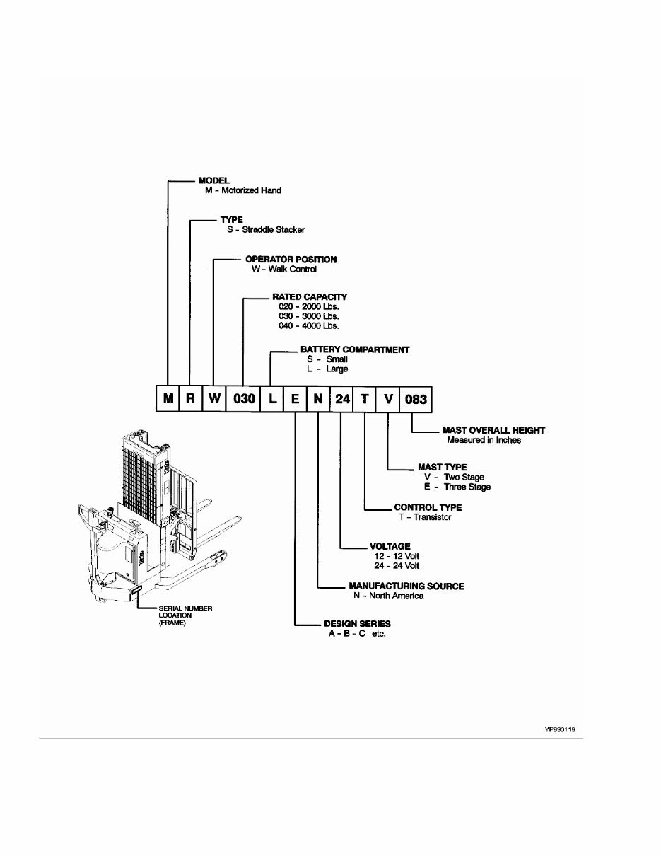
MODEL NOMENCLATURE NOTE: This parts manual contains alternate pages for certain assemblies. The truck model code can be used to determine many of the assemblies on your lift truck (power, tire type, mast type). The complete truck model and serial number are stamped into the nameplate. See Identification of Truck Serial Number on Page vii for further information.
SECTIONS 1 GENERAL TRUCK 2 ELECTRICAL SYSTEM 3 DRIVE UNIT AND BRAKE ASSEMBLY 4 CONTROL HANDLE 5 LOAD WHEEL 6 HYDRAULIC SYSTEM 7 LIFTING MECHANISM 8 OPTIONS 9 NUMERICAL INDEX 10 USER SUPPORT INFORMATION This Parts Manual is divided into 10 major sections which are listed above. Quick reference to these sections can be made by placing the right thumb on the tab of the desired section, bending the book back and thumbing the pages to the corresponding tab.
GENERAL INFORMATION ALPHABETICAL INDEX DESCRIPTION PAGE NO. A ABBREVIATIONS QUICK REFERENCE SHEET ................................................................................................... iv ALPHABETICAL INDEX............................................................................................................................................ i B BATTERY DISCONNECT ................................................................................................................................... 1-14 BATTERY ROLLER .............................................................................................................................................. 8-2 BATTERY SPACER ............................................................................................................................................ 1-16 C CHAINS, PINS, AND ANCHORS THREE STAGE FULL FREE-LIFT MRW020-030E ............................................................................................................................................ 7-10 MSW 030-040E ........................................................................................................................................... 7-12 TWO STAGE LIMITED FREE-LIFT MRW020-030E ............................................................................................................................................ 7-14 MSW030-040E ............................................................................................................................................ 7-16 CONTROL HANDLE ARM ASSEMBLY................................................................................................................ 4-2 SEMI-ROTARY .................................................................................................................................................. 8-4 CONTROL HANDLE ASSEMBLY......................................................................................................................... 4-4 OPTIONAL ........................................................................................................................................................ 8-6 CONTROL PANEL ASSEMBLY ............................................................................................................................ 2-2 COVERS .............................................................................................................................................................. 1-2 E ELECTRIC BRAKE............................................................................................................................................... 3-2 ELECTRICAL ARRANGEMENT .......................................................................................................................... 2-4 EXTENDED CYLINDER ASSEMBLY MRW020-030E ............................................................................................................................................... 7-18 F FORK CARRIAGE MSW 030-040E............................................................................................................................................... 7-42 FORKS HOOK TYPE CARRIAGE ................................................................................................................................. 1-8 FREE-LIFT CYLINDER ASSEMBLY MRW020-030E ............................................................................................................................................... 7-20 MSW 030-040E THREE STAGE FULL FREE-LIFT .............................................................................................................. 7-22 H HEADER HOSE GROUP MRW020-030E ............................................................................................................................................... 7-24 HOW TO FIND THE DESIRED PART NUMBER ..................................................................................................... vi HOW TO USE THE ILLUSTRATED PARTS MANUAL ............................................................................................ vi HYDRAULIC POWER UNIT REACH ............................................................................................................................................................. 6-2 i
GENERAL INFORMATION DESCRIPTION PAGE NO. H (continued) WITH AUXILIARY ............................................................................................................................................. 6-4 WITHOUT AUXILIARY S/N C820N-0152Z⇒ ..................................................................................................................................... 6-8 ⇒S/N C820N-0152Z ..................................................................................................................................... 6-6 HYDRAULIC SYSTEM ....................................................................................................................................... 6-10 I IDENTIFICATION OF MAST SERIAL NUMBER ................................................................................................... viii IDENTIFICATION OF TRUCK SERIAL NUMBER .................................................................................................. vii INNER CARRIAGE MRW020-030E ............................................................................................................................................... 7-44 INTEGRAL TILT ASSEMBLY MRW020-030E ............................................................................................................................................... 7-26 WITH SIDESHIFT MRW020-030E ............................................................................................................................................ 7-28 L LABELS AND DECALS ........................................................................................................................................ 1-4 LIFT CYLINDER ASSEMBLY MRW020-030E ............................................................................................................................................... 7-30 MSW 030-040E THREE STAGE FULL FREE-LIFT .............................................................................................................. 7-32 TWO STAGE LIMITED FREE-LIFT ............................................................................................................. 7-34 LIFT CYLINDER INSTALLATION MRW020-030E ............................................................................................................................................... 7-36 MSW 030-040E THREE STAGE FULL FREE-LIFT .............................................................................................................. 7-38 TWO STAGE LIMITED FREE-LIFT ............................................................................................................. 7-40 LOAD BACKREST MRW20-30E ................................................................................................................................................... 1-10 MSW30-40E.................................................................................................................................................... 1-12 LOAD WHEEL ...................................................................................................................................................... 5-2 FIXED TANDEM.............................................................................................................................................. 8-12 M MASTER DRIVE UNIT ......................................................................................................................................... 3-8 MASTER DRIVE UNIT ASSEMBLY ..................................................................................................................... 3-4 MASTER PART SHEET CROSS-REFERENCE ..................................................................................................... ix O OPERATOR GUARD ............................................................................................................................................ 1-6 THREE STAGE FULL FREE-LIFT .................................................................................................................. 8-14 TWO STAGE LIMITED FREE-LIFT................................................................................................................. 8-16 ii
GENERAL INFORMATION DESCRIPTION PAGE NO. S SCISSOR CARRIAGE MRW020-030E ............................................................................................................................................... 7-48 SIDE-SHIFT ASSEMBLY HANG-ON TYPE............................................................................................................................................... 8-8 SIDE-SHIFT CYLINDER HANG-ON TYPE............................................................................................................................................. 8-10 T TRACTION MOTOR ............................................................................................................................................. 2-6 U UPRIGHTS THREE STAGE FULL FREE-LIFT .................................................................................................................... 7-2 TWO STAGE LIMITED FREE-LIFT................................................................................................................... 7-6 Z ZAPI-HANDSET KIT........................................................................................................................................... 8-18 ZAPI-LAPTOP/PC KIT (WINDOWS) .................................................................................................................. 8-19 iii
GENERAL INFORMATION ABBREVIATIONS QUICK REFERENCE SHEET Listed below are abbreviations used in parts manuals to denote the following expressions: TERM DEFINITION TERM DEFINITION Amp Amperes AR As Required BDI Battery Discharge Indicators BWI Brush Wear Indicator CE Communicator End CRE Corrosive Environment D/B Date Break dbA Decibel "A" Scale DE Drive End ECM Electronic Control Module ECN Engineering Change Notice EEPROM Electrically Erasable Programmable Read Only Memory EPROM Electrically Programmable Read Only Memory FRE Freezer Environment in. inches LPG Liquefied Petroleum Gas MAP Manifold Absolute Pressure mm millimeters MSTS Microprocessor Spark Timing System NPT National Pipe Threads O/S Oversize PTO Power Take Off RPM Revolutions per Minute S/N Serial Number TMM Truck Management Module UL Type D Diesel-Powered Safety Rating UL Type DS Diesel-Powered Safety Rating UL Type E Battery-Powered Safety Rating UL Type EE Battery-Powered Safety Rating UL Type ES Battery-Powered Safety Rating UL Type G Gasoline-Powered Safety Rating UL Type GS Gasoline-Powered Safety Rating UL Type LP Gas-Powered Safety Rating UL Type LPS LP Gas-Powered Safety Rating U/S Undersize UL Underwriters Laboratory V Volts iv
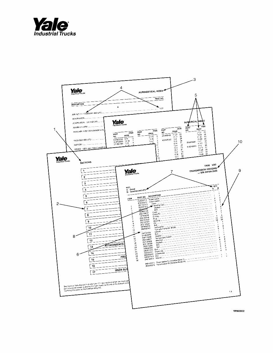
GENERAL INFORMATION HOW TO USE THE ILLUSTRATED PARTS MANUAL This parts manual describes and illustrates assemblies, subassemblies, and detail parts needed for service replacement. The different constructions are indicated by keys and footnotes. The callouts correspond to descriptions found on the next page. v
GENERAL INFORMATION HOW TO FIND THE DESIRED PART NUMBER WHEN THE PART NUMBER AND THE NEXT HIGHER ASSEMBLY IS NOT KNOWN: 1. Determine the function and application of the part required. Turn to the Sections Page. Choose the general area of reference most likely to include the part. 2. Turn to the section you chose. Use the Section Table of Contents to determine the assembly which would normally contain the part required. Then locate the part on the assembly breakdown page. WHEN THE PART NUMBER IS NOT KNOWN AND THE NEXT HIGHER ASSEMBLY IS KNOWN: 3. Determine the assembly the required part is used on. Turn to the Alphabetical Index on Page i. 4. Locate the assembly the required part is used on and turn to the page indicated for that assembly. Then locate the part on the assembly breakdown page. WHEN THE PART NUMBER IS KNOWN: 5. Use the Numerical Index on Page 9-1 to find the part number. Turn to the page listed and locate the part as indicated by the item number. GENERAL: The assembly breakdowns include part numbers, descriptions, quantities required, keys and footnotes to help in selecting correct parts. 6. Five periods in the PART NO. column (.....) indicate that the part is either Not Serviced Separately or there is a reference to another figure. A figure reference is denoted by a pointing hand followed by a parts page number in the DESCRIPTION column (☞7A56) 7. Keys are used to show two or more similar assemblies, RH and LH assembly parts, etc. Select the appropriate key, "A", "B", "C", "D", or "E" and the corresponding quantity column to find the required parts. Two periods in the QTY column (..) indicate that the part is not used for that assembly. 8. Indented descriptions under the DESCRIPTION column are used to indicate assemblies and subparts of assemblies. In the example on the previous page, BEARING CAP (Item 2) is a subpart of the major assembly CASE. 9. Quantities shown are for one assembly. The quantities of the subpart BEARING CAP are indicated as two and two. This means two per CASE assembly. 10. Serial number breaks identify the most current parts information and are shown as follows: ⇒ S/N A810N-2639 Indicates last serial number affected. S/N A810N-2640 ⇒ Indicates the first serial number affected. S/N A810N-1553 ⇔ S/N A810N-3291 Indicates a range of serial numbers affected. ECN numbers for pending serial numbers are shown to allow for the inclusion of the most current parts information and are identified as follows: ⇒ S/N Pending Per ECN 63243 Indicates a pending serial number for last unit affected. S/N Pending Per ECN 63243 ⇒ Indicates a pending serial number for first unit affected. Date breaks are used to indicate when a change occurred but a subsequent serial number break was not recorded. This is an arbitrary date usually based on the ECN release and are identified as follows: ⇒ D/B 3/00 Indicates that a change occurred sometime within that month for the item affected. D/B 3/00 ⇒ Indicates that a change occurred sometime within that month for the item affected. D/B 3/00 ⇔ D/B 4/00 Indicates a range of production dates of the item affected. Contact your local dealer for Yale lift trucks for serial number information for items with a ECN or a date break. ORDERING PARTS: When ordering replacement parts, give the unit serial number, part number, name of part and quantity required. For any further information on parts, service, or ordering, consult your local dealer for Yale lift trucks. vi
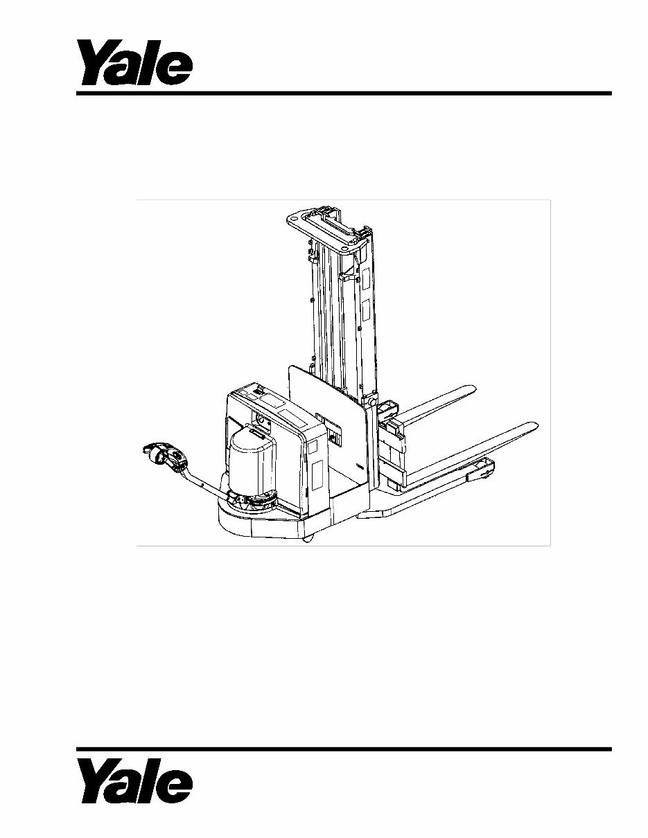
This is a comprehensive factory Parts manual for the Yale MSW 030-E MSW 040-E (C820), MRW 020-E MRW 030-E (C821) Lift Truck. The manual features easy-to-read text sections with high-quality diagrams and instructions, making it suitable for both do-it-yourselfers and experienced mechanics. It includes step-by-step instructions and detailed exploded pictures and diagrams to assist in completing the required job correctly and efficiently.
The Yale MSW 030-E MSW 040-E (C820), MRW 020-E MRW 030-E (C821) Lift Truck Parts Manual covers every single detail of the machine and provides step-by-step instructions based on the complete disassembly of the machine, offering an inexpensive way to ensure the proper functioning of your vehicle.
Models:
MSW 030-E
MSW 040-E
(C820)
MRW 020-E
MRW 030-E
(C821)
Manual Covers:
General Truck
Electrical System
Drive Unit And Brake Assembly
Control Handle
Hydraulic System
Lift Linkage And Load Wheel
Options
Numerical Index
User Support Information
And More......
File Format: PDF
Compatibility: All Versions of Windows & Mac
Language: English
Requirements: Adobe Reader & Win
No waiting, all pages are printable. The Yale MSW 030-E MSW 040-E (C820), MRW 020-E MRW 030-E (C821) Lift Truck Parts Manual saves you money on postage and packaging. It is great to have.

, MRW 020-E MRW 030-E (C821) Lift Truck Parts Manual")