BRAKING SYSTEM UPDATE Part No.: 524259539 6 5 4 3 0 1 2 Page: 1 SERVICE Dec. 2005 BRAKING SYSTEM 1.00 ELECTROMAGNETIC BRAKE COMPONENTS OF THE DRIVE MOTOR............................................................................2 2.00 BRAKING SYSTEMS........................................................................................................................................... 3 3.00 REMOVAL OF THE ELECTROMAGNETIC BRAKE....................................................................................................................4 3.01 REMPLACEMENT OF THE ELECTROMAGNETIC BRAKE ................................................................ 5
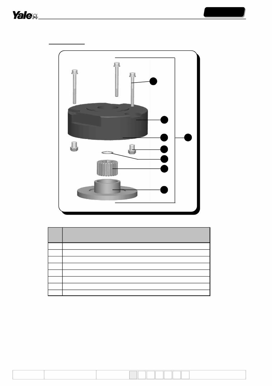
BRAKING SYSTEM UPDATE Part No.: 524259539 6 5 4 3 0 1 2 Page: 2 SERVICE Dec. 2005 OPERATION The electromagnetic brake, which is fixed on the drive motor, is only a parking brake with STOP or EMERGENCY function and it is a spring-loaded brake. When the electromagnet is supplied, it attracts the braking plate (ref.4) and releases the brake lining making it rotate freely. When the electromagnet is no more supplied, the springs push the plate downward on the brake lining enabling the braking. 4 6 8 3 5 1 7 2 Ref. Description 1 Complete electromagnetic brake 2 Unit fixing bolts 3 Electromagnet 4 Braking plate 5 Lining adjusting nut 6 Snap ring 7 Lining guide pinion 8 Lining 1.00 ELECTROMAGNETIC BRAKE COMPONENTS OF THE DRIVE MOTOR MODEL: ALL MODELS
BRAKING SYSTEM UPDATE Part No.: 524259539 6 5 4 3 0 1 2 Page: 3 SERVICE Dec. 2005 2.00 BRAKING SYSTEMS There are 3 braking systems: • Release breaking. • Inversion braking. • Emergency and parking braking. A) RELEASE BRAKING It controls the deceleration ramp when the drive control is released. B) INVERSION BRAKING It controls the deceleration ramp when the drive control is inverted. The “inversion braking” called also reverse current braking is consists in reversing the current on the motor by changing the direction of travel when the truck is driving. The braking current must be adjusted so that the truck can stop within a distance not smaller than the length of the truck. C) EMERGENCY AND PARKING BRAKING The “emergency and parking braking” is obtained by the electromagnetic brake fixed on the drive motor. The excessive decreasing of the braking space may compromise the good operation of some components of the truck, since during the braking the current on the motor reaches very high values thus causing (in case of wrong adjustment) an early wear of the brushes, the drive motor manifold and the drive wheel.
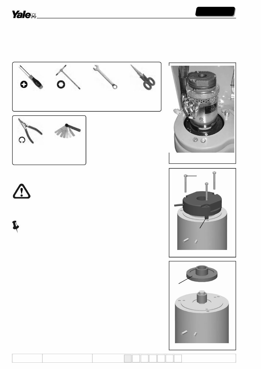
BRAKING SYSTEM UPDATE Part No.: 524259539 6 5 4 3 0 1 2 Page: 4 SERVICE Dec. 2005 3.00 REMOVAL OF THE ELECTROMAGNETIC BRAKE: REPLACEMENT OF THE COMPLETE BRAKE, REPLACEMENT OF THE BRAKE LINING Procedure Before starting to work wear suitable safety clothes. Park the truck in a safe area, away from the transit of other motor vehicles and from the passage of pedestrians. Lower the forks to the ground, turn the key OFF and disconnect the battery. If the drive wheel brake lining is replaced, the guide pinion must be replaced too. Step 2 OPEN ENDED SPANNER - “T” SHAPED WRENCH - SCISSORS By using the open ended spanner loosen the three stop nuts (ref.A fig.1). By using the “T-shaped” wrench loosen the three screws fastening the electromagnetic brake to the drive motor (ref.B fig.1). By using the scissor cut the cable clamp to release the electromagnetic brake supply cable. Disconnect the connector and extract it from the retainer. Remove the brake from the motor. 5 mm Allen wrench feeler gauge 13 mm open ended spanner scissors external circlip pliers Necessary standard tools Fig. 2 large slotted screwdriver Step 1 LARGE SCREWDRIVER Loosen the screws fastening the motor bonner. Remove the bonnet. Fig. 1 A B Fig. 3 C
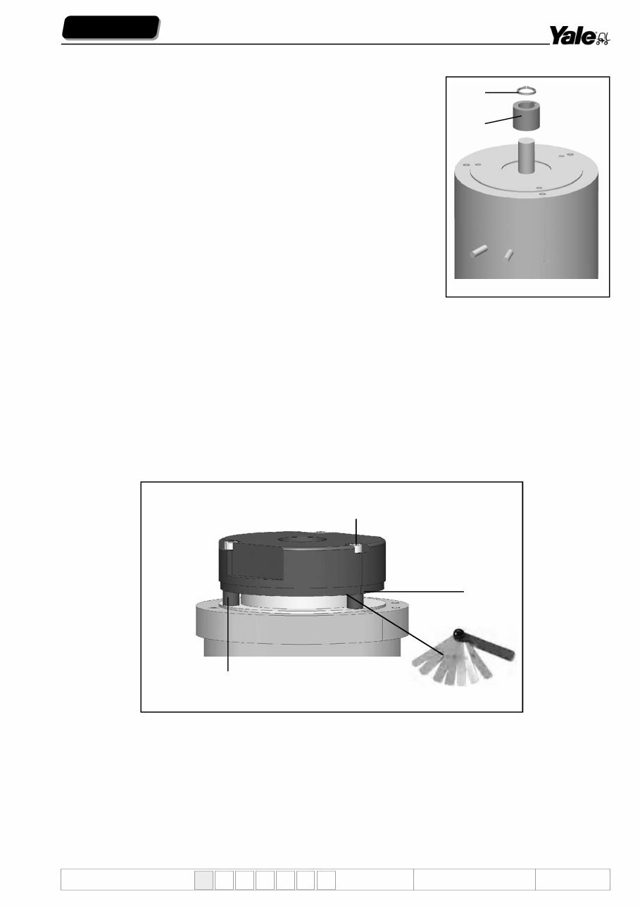
BRAKING SYSTEM UPDATE Part No.: 524259539 6 5 4 3 0 1 2 Page: 5 SERVICE Dec. 2005 3.01 ADJUSTMENT OF THE ELECTROMAGNETIC BRAKE After assembling the electromagnetic brake unit, it is necessary to adjust the brake lining before using the truck. For a good braking the distance between the brake lining and the electromagnet (ref.F fig.5) must be not higher than 0.35 mm. Therefore a feeler gauge of that measure is required. Keep the three nuts loosened (ref.G fig.5), insert the feeler gauge near a bolt (ref.H fig.5), tighten the fastening screw by means of the Allen wrench (ref.I fig.5) Allen wrench and bring the plate nearer at a distance that allows extracting the feeler gauge with a little friction. Repeat the operation on all three bolts. Tighten the nuts by means of the open ended spanner (ref.G fig.5). Step 3 EXTERNAL CIRCLIP PLIERS Extract the brake lining (ref.C fig.2) from the guide pinion. By using the circlip pliers remove the snap ring from the motor shaft (ref.D fig.4) and extract the guide pinion (ref.E fig.4). Replace the brake lining and the guide pinion. For the assembly carry out the operation in the reverse order. After the assembly carry out the adjustment Fig. 4 D E Fig. 5 I G H F
You're Reading a Preview
What's Included?
Lifetime Access
Fast Download Speeds
Offline Viewing
Access Contents & Bookmarks
Full Search Facility
Print one or all pages of your manual
$46.99
YALE (B845) MS10E Lift Truck Service Repair Manual
If you are facing issues with YALE (B845) MS10E LIFT TRUCK maintenance, this service repair manual is the solution you need. It is a comprehensive guide that caters to both professional mechanics and DIY enthusiasts. The manual provides rich maintenance knowledge, practical insights, and detailed instructions for installation, adjustment, and maintenance. It covers various aspects including preface, introduction, installation and settings, electrical system, hydraulics, frame mechanics, mast mechanics, reduction gear, braking system, and technical information.
The manual is available in electronic format, compatible with all versions of Windows & Mac, and is in English language. It is accessible using Adobe Reader & Win. With this manual, you can ensure that your YALE (B845) MS10E LIFT TRUCK receives the best service. The electronic format makes it practical, easy to carry, and readily available for reference at any time and place.
Electronic service repair manuals are in line with the modern trend of electronic products, making them a fashionable and convenient choice for maintenance needs. Whether you are a professional mechanic or an individual user, this YALE (B845) MS10E LIFT TRUCK service repair manual will be your reliable partner in resolving maintenance difficulties.
Reviews
Q&A
Recently Viewed
5,521,897Happy Clients
2,594,462eManuals
1,120,453Trusted Sellers
15Years in Business
Price:
Actual Price:
YALE (B845) MS10E Lift Truck Service Repair Manual




 Lifetime Access




