Revision No. Date Description of Changes Approval Issued by Revision Record 0 2000.08.01 First Edition Inagaki Kaneko 1 2000.09.13 3-6 (p.29) CUTTER PROTECTION REPLACEMENT Inagaki Kaneko 2 2000.10.17 4-2, 4-3 Additional : Tool Presure Control Command !FS Inagaki Kaneko 3 2001.01.15 1-2 Parts List : L-BEARING,RSR9ZMUUC1 Inagaki Kaneko 1-3 Parts List : STAY,CARRIAGE
To Ensure Safe Work To Ensure Safe Work About WARNING and CAUTION Notices Used for instructions intended to alert the operator to the risk of death or severe injury should the unit be used improperly. Used for instructions intended to alert the operator to the risk of injury or material damage should the unit be used improperly. * Material damage refers to damage or other adverse effects caused with respect to the home and all its furnishings, as well to domestic animals or pets. About the Symbols The symbol alerts the user to items that must never be carried out (are forbidden). The specific thing that must not be done is indicated by the design contained within the circle. The symbol at left means not to touch. The symbol alerts the user to things that must be carried out. The specific thing that must be done is indicated by the design contained within the circle. The symbol at left means the power-cord plug must be unplugged from the outlet. Turn off the power SW before servicing. The symbol alerts the user to important instructions or warnings. The specific meaning of the symbol is determined by the design contained within the triangle. The symbol at left means "danger of electrocution." WARNING CAUTION WARNING
-- MEMO --
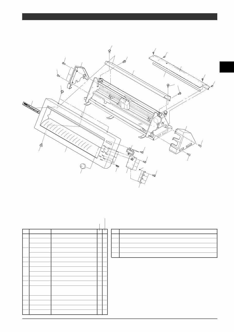
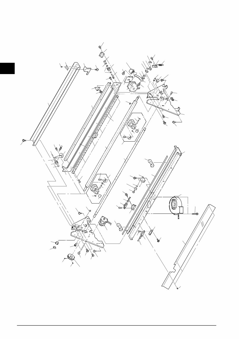
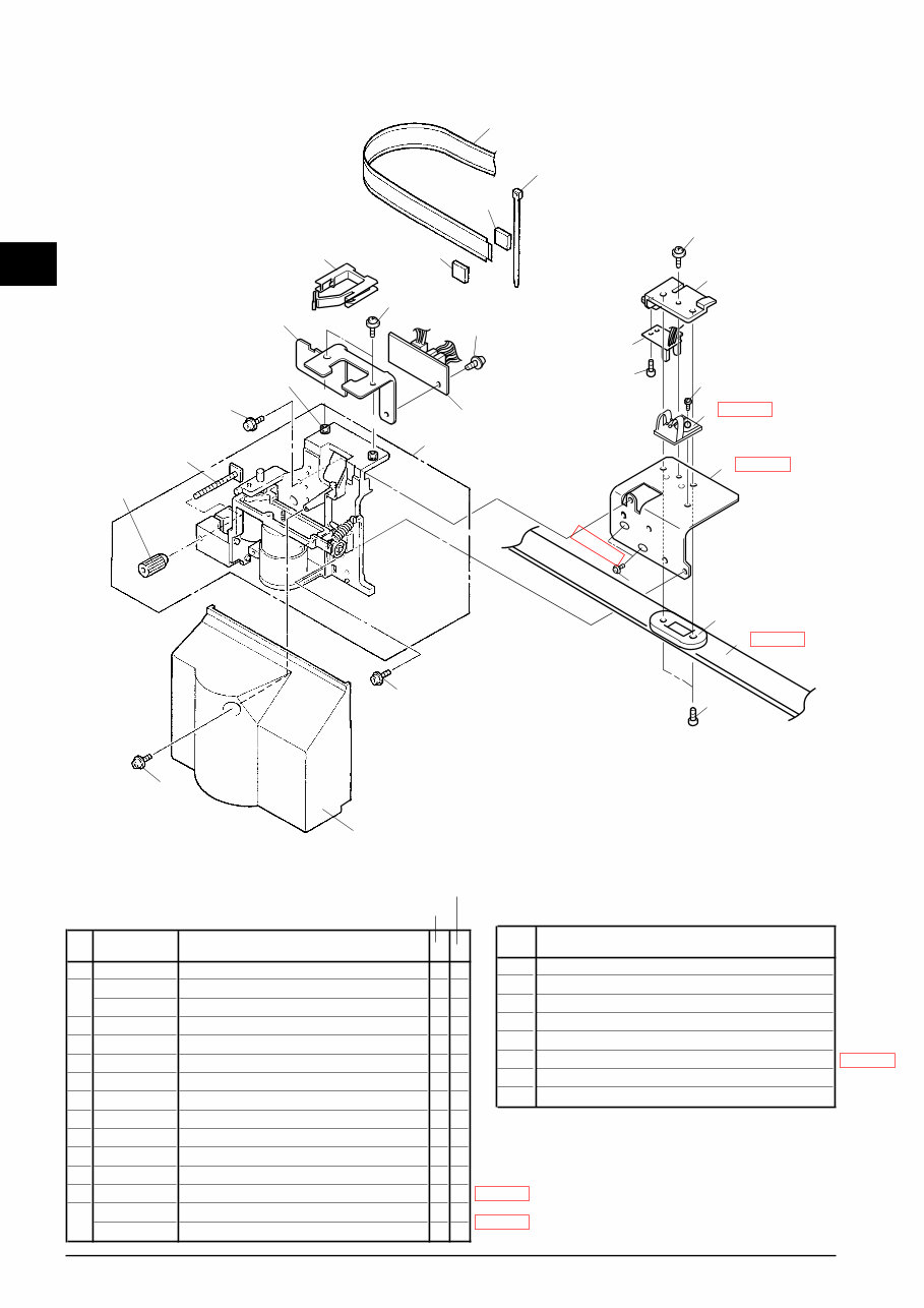
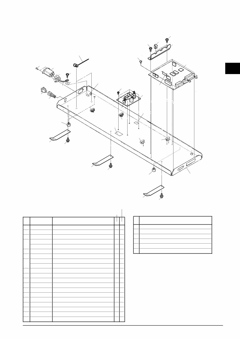
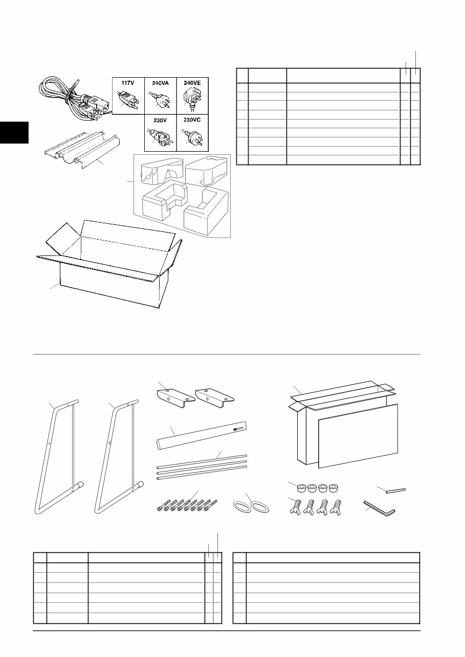
1 1 1 Structure & Spare Parts 1-1 COVERS 4 6 3 5 1 10 12 11 7 8 2 9 13 S1 S1 S4 S4 S4 S4 S4 S4 S4 S1 S1 S5 S5 S2 S3 S3 CX-12 CX-24 PARTS LIST -Main Parts- Parts No. Parts Name 1 22805381 ASS'Y,LCD CX-24 * * 22025409 COVER,FRONT CX-12 * 22025408 COVER,FRONT CX-24 * 22025428 COVER,GUIDE R2 CX-12 * 22025427 COVER,GUIDE R2 CX-24 * 4 22025406 COVER,SIDE L CX-24 * * 5 22025407 COVER,SIDE R CX-24 * * 22025411 COVER,Y RAIL CX-12 * 22025410 COVER,Y RAIL CX-24 * 7 22495206 KEY TOP,CX-24 * * 8 22475108 KNOB,CX-24 * * 9 22535235 LABEL,CORPORATE LOGOTYPE #LA97 * * 10 7501623020 PANEL BOARD ASS'Y * * 11 12259222 SHIELD,E01S03-1YAMA * 12 22255221 SHIELD,PANEL R CX-24 * * 13 21395112 TAPE,FELT CX-24 * 2 3 6 PARTS LIST -Supplemental Parts- Parts Name S1 SCREW,BINDING HEAD M4x5 Ni S2 SCREW,BINDING HEAD P-TIGHT M3x6BC S3 SCREW,BINDING HEAD P-TIGHT M3x8C S4 SCREW,BINDING HEAD WITH TEETH WASHER M3x8Ni S5 SCREW,W-SEMS M3x8BC
This is a comprehensive service manual designed for modifying, repairing, and maintaining Roland products. It includes specifications, parts list, exploded views, circuit board diagrams, and more. Whether you are a professional mechanic or a DIY enthusiast, this manual provides detailed instructions and high-quality images to assist you in servicing your device.
Specifications
Panel Layout
Circuit Board Layout
Block Diagram
Disassembly Procedure
LSI Pin Description
IC Block Diagram
Circuit Boards
Inspection
MIDI Implementation Chart
Overall Circuit Diagram
Parts List
This official service and repair manual is available in PDF format, ensuring high-resolution quality for printing. Upon payment, you will have instant access to the manual without any shipping delays, making it convenient for immediate repairs. The manual is compatible with various platforms including Windows, MAC, and Linux.
If you require service manuals for other Roland products, feel free to inquire. Thank you for choosing this service manual for your repair needs!
Recently Viewed
5,521,897Happy Clients
2,594,462eManuals
1,120,453Trusted Sellers
15Years in Business
Price:
Actual Price:
Roland cx24 cx-24 cx12 cx-12 camm1 camm-1 service manual