

Holset Turbochargers OEM Service & Repair Manual
What's Included?
Fast Download Speeds
Offline Viewing
Access Contents & Bookmarks
Full Search Facility
Print one or all pages of your manual
Holset WH2D
Service Repair Manual
Copyright 2007, Cummins Turbo Technologies Ltd. All rights reserved.
VGT, Command Valve and Super MWE are trade marks of Cummins Turbo Technologies Ltd.
Holset and the Holset Logo are registered trade marks of Cummins Turbo Technologies Ltd.
Cummins and the Cummins logo are registered trade marks of Cummins Inc.

WH2D Service Repair Manual Foreword
Foreword
This publication was written to assist with turbocharger installation, maintenance and overhaul. It is not a
warranty of any kind expressed or implied.
The specifications and procedures in this manual are based on information in effect at the time of publication.
Holset Service reserves the right to make any changes at any time without obligation. If differences are found
between your turbocharger and the information in this manual, contact your local Holset approved agent.
The latest technology and the highest quality standards are used in the manufacture of Holset Turbochargers.
When replacement parts are needed, we recommend using only genuine Holset parts.

WH2D Service Repair Manual Table of Contents
Table of Contents
1: Introduction
About the Manual . . . . . . . . . . . . . . . . . . . . . . . . . . . . . . . . . . . . . . . . . . . . . . . . . . . . 1:1
How to Use the Manual . . . . . . . . . . . . . . . . . . . . . . . . . . . . . . . . . . . . . . . . . . . . . . . . 1:1
How to Order Holset Original Parts. . . . . . . . . . . . . . . . . . . . . . . . . . . . . . . . . . . . . . . 1:1
Description and Operation of Turbocharger ............................. 1:2
General Information ............................................. 1:2
Introduction to Turbocharger Matching ............................... 1:2
Notes, Cautions and Warnings ..................................... 1:3
Installation Data..................................................... 1:4
Installation Checklist ................................................ 1:5
Symbols ........................................................... 1:6
2: Component Identification
Turbocharger Identification ........................................... 2:1
Dataplate and CHRA (Core) of Turbocharger .......................... 2:1
Exploded Views ..................................................... 2:2
Component List ..................................................... 2:3
Purchasable Service Tools............................................ 2:5
3: Troubleshooting and Diagnosis
Fault Finding Chart .................................................. 3:1
4: Component Testing and Replacement
Service Tools ....................................................... 4:1
On Engine Checks .................................................. 4:2
Bearing Clearance ................................................... 4:5
Turbine and Compressor Housings .................................... 4:6
Cleaning of Housings ............................................... 4:13
Wastegate Actuator Checks .......................................... 4:15
Actuator Removal................................................... 4:17
Wastegate Mechanism Check ......................................... 4:18
Actuator Replacement ............................................... 4:20
5: Turbocharger Service and Overhaul
Service Tools ....................................................... 5:1
Disassembly ....................................................... 5:2
Component Cleaning ................................................ 5:7
Inspection and Testing ............................................... 5:9
Reassembly ....................................................... 5:13
6: Service Data Sheets
H Range Service Data Sheets . . . . . . . . . . . . . . . . . . . . . . . . . . . . . . . . . . . . . . . . . . 6:1

WH2D Service Repair Manual Introduction
1:1
About the Manual
The procedures in this manual were developed to instruct in the correct overhaul of the designated Holset
turbocharger range for optimum performance and minimum maintenance operation.
How to Use the Manual
The manual is split into sections designed to provide service information in a logical sequence. The manual
contains links to help the user navigate between relevant sections. Users who are unfamilier with navigating in
PDF documents are refered to Navigating in PDF documents in the Adobe® Acrobat® Reader™ help file.
Contents is an interactive page with links to all the sections. It can be accessed from any page
in the manual by clicking this icon.
Section 1 defines the layout of the manual, introduces the reader to the operation of the turbocharger
and presents important installation guidelines.
Sections 2, 3 and 4 concentrate on Turbocharger Component Identification, Troubleshooting and
Diagnosis, Component Testing and Replacement.
Section 5 identifies the Service and Overhaul procedures to be followed in the unlikley event of a
major turbocharger malfunction.
Section 6 quantifies build data to ensure the turbocharger will continue to operate to Holset Service
standard on completion of overhaul.
Manual sections 1 to 5 where applicable, appear as a self extracting compressed file which is organised
according to the steps needed to most easily and correctly maintain the operation of the turbocharger. Users
are required to download this file to hard disk. Section 6 has its own file identity and resides at
www.holset.co.uk. so that Holset can update the Service Data as changes occur. The links between manual
and service data are active only when the user is connected to the Internet.
Chapter 6 has an expiry date to encourage users to discard outdated saved or printed versions and always
access the latest information available at www.holset.co.uk.
When using the manual on-line this icon will link to Holset’s website to help find your nearest agent
for advice and how to order Holset original parts.
How to Order Holset Original Parts
To make sure of optimum performance, certain items must be discarded during disassembly and replaced with
new for re-assembly. These items are indicated in the Service and Overhaul section with the use of a
*
symbol.
All items showing a
*
are available in a basic overhaul kit.
To get the correct parts for your turbocharger, refer to the ‘component identification’ section of this manual to
help you find the following information:
1) Refer to the exploded view and component list to define the major components to be replaced.
2) Refer to the turbocharger’s dataplate which will be found on the compressor housing or wastegate
actuator to define the identifying information about your turbocharger build standard.
3) Contact your local Holset agent with componant identification nos. and dataplate assembly no., serial
no. and turbocharger type.
4) With this information, your local agent can provide you with the optimum kit of parts for re-assembling
your turbocharger for continued long life operation.

WH2D Service Repair Manual Introduction
Description and Operation of Turbocharger
1:2
General Information
A turbocharger is a mechanical device which uses the engine’s exhaust gases to force more air into the engine
cylinders. Hot exhaust gas energy is used to turn a turbine wheel and shaft. At the other end of the shaft is the
compressor impeller (or compressor wheel), which draws in air and forces it into the engine cylinders.
Supplying increased air mass flow to the engine provides improved engine performance, lower exhaust smoke
density, improved operating economy and altitude compensation. The turbocharger has proven to be one of the
most beneficial devices for improving engine performance. It performs its job very well, as long as it is properly
cared for.
Introduction to Wastegate Turbochargers
The need for wastegated turbochargers
A standard turbocharger can be perfectly matched to only one particular engine condition, eg maximum torque
speed or maximum load speed. At this engine speed, the turbocharger supplies the optimum mass of air to
give the required air/fuel ratio. At other speeds the air/fuel ratio cannot be held at the optimum hence fuel
consumption and emission levels worsen.
Engine emission legislations have forced manufacturers to improve their engine efficiencies, particularly at low
speeds where low air/fuel ratios cause high smoke levels.
The Holset integral wastegate turbocharger is a cost effective solution to this problem and for a small increase
in complexity, a simple variable flow turbine housing has been achieved.
Integral wastegate turbochargers have been available for passenger cars for many years. Holset has
developed
such a turbocharger with components designed for extended life equal to that of standard commercial vehicle
turbochargers.
The importance of correctly servicing the wastegate actuator mechanism
A wastegate turbocharger requires accurate setting at point of manufacture. It is very important to adhere
to setting limits when servicing the turbocharger, as failure to do so could result in turbocharger or engine
failure.
Effects of wrong setting
Possible consequences if turbocharger boost pressure is too low:-
• Engine runs fuel rich • Fuel consumption increase
• Exhaust temperature increase • Smoke levels increase
• Hydrocarbon levels increase • Risks of failing emissions tests
• High cylinder temperature risks
damage to engine pistons
Possible consequences if turbocharger boost pressure is too high:-
• Engine runs fuel weak (lean) • Nitrous oxide levels increase
• Excessive boost overspeeds • Turbocharger bearing failure and
turbocharger wheel fatigue problems
• Increased cylinder pressure risks damage • Intercooler load increases causing engine
to engine head gasket, pistons and valves to overheat, risking piston damage
WH2D Service Repair Manual Introduction
1:3
Notes, Cautions and Warnings
Notes, Cautions and Warnings are used in this manual to emphasise important or critical instructions.
Note
Information which is essential to highlight.
Caution
Maintanence or Service procedures which if not strictly followed, will result in damage or destruction of the
turbocharger.
Warning
Maintanence or Service procedures which if not correctly followed will result in personal injury or loss of life.
Note
Holset Service receives many turbocharger returns that are no fault found. Before assuming the turbocharger
is not performing to specification always refer to the engine diagnostic system and the troubleshooting
diagnostic procedures of this manual.
Warning
Turbocharger surface temperature during operation can achieve 700°C (1300°F). The designated
turbocharger range weighs up to 21.7 kg (47.2 lb) and is fitted with external parts that are sensitive to manual
handling.
Caution
This turbocharger has been manufactured using piece part and rotor balance processes and MUST be
check balanced on rebuild.
If you intend to overhaul/repair a rotor balanced turbocharger, ensure that all the rotor parts have co-relation
marks prior to disassembly so that they can be reassembled in the same relative positions.
Balance limits for turbocharger rebuild are shown on Holset’s Service Data Sheet.
It is important to note that operating a turbocharger with a rotor or core balance level greater than the
published limits could cause turbocharger or engine failure. If you are in any doubt regarding the balancing
process, please contact an approved Holset agent for assistance.
Caution
Never remove the wastegate actuator or mounting bracket from the turbine housing, unless the actuator is to
be renewed. It is possible to leave the turbine housing, bracket and actuator as an assembly while servicing
the turbocharger.
Never adjust the link-rod of an assembled wastegate turbocharger. The link-rods are set by the O.E. supplier
to precise limits which must be adhered to.
Always check that the actuator and wastegate mechanism is still in good working order, before proceding with
disassembly of your wastegate turbocharger.
Warning
Some parts are manufactured in fluoroelastomers (e.g. Viton) or similar that requires special treatment during
repair and service after fire.
Note
Holset turbochargers can be remanufactured using recovered parts. Where it is necessary to dispose of
components or whole turbochargers, an environmentally responsible process such as recycling should be
used, with due regard to local laws.

WH2D Service Repair Manual Introduction
Installation Data
1:4
1. Holset Service receives many turbocharger returns that are no fault found. Before assuming the
turbocharger is not performing to specification always refer to the engine diagnostic system and the fault
finding chart of this manual to make all the recommended health checks.
2. It is important that intake and exhaust systems are fitted in accordance with the recommendations of
the Equipment and Engine manufacturers. Limiting mass inertia loading is critical to turbocharger wholelife
operation. Maximum engine vibration input must not exceed 10g.
3. The air filter must remove particles greater than 5μm at an efficiency of 95% and be of sufficient capacity
to match the air consumption of the engine. Recommended filters should always be used with a pressure
drop indicator. Intake systems must be capable of withstanding depressions up to 6.9 kPa (1.0 lbf/in
2
).
4. Hose and clip connections of intake manifold systems must be capable of withstanding the turbocharger
pressure ratio. V band clamps are preferred and must be used above 3:1 pressure ratio.
5. Exhaust systems must be capable of operating at exhaust back pressures of up to 10 kPa (1.5 lbf/in
2
).
This limit is increased to 13.4 kPa (2.0 lbf/in
2
) if a catalytic converter is fitted. Exhaust brake applications
are permitted to impose 450 kPa (65.3 lbf/in
2
) back pressure.
6. Oil should be filtered to 10μm with efficiency of 60% TWA (Time Weighted Average) /20 μm with efficiency
of 85% TWA. Efficiency assessed using ISO Standard 4572/SAE J 1858.
7. The oil quality must be as specified by the engine manufacturer and will be a minimum API SE - CD
(MIL - L - 2104C) specification. Improved life can be obtained by using super high performance diesel
(SHPD) oils, particularly in industrial applications which use extended oil drain periods.
8. Normal oil temperature is 95+/-5°C (203+/-9° F). It should not exceed 120°C (248°F) under any operating
condition.
9. Any pre-lube oil must be clean and meet the minimum CD classification.
10. The orientation of turbine housing, bearing housing and compressor cover is fixed according to
application. During installation, do not attempt to rotate these components. Inclined turbocharger
installation is not recommended. If an installed angle is necessary, oil inlet centreline must be +/- 10
degrees from vertical and rotor centreline +/- 5 degrees from horizontal.
11. Holset permits oil return pipes to decline at an overall angle of not less than 30 degrees below horizontal.
All turbocharger applications require a pipe of internal diameter greater than 19 mm which has integrated
connectors. To ensure oil returns into the engine under all operating conditions, the return connection
into the engine sump must not be submerged and the outlet flange of the turbocharger must be 50 mm
above the maximum oil level of the engine sump pan. Crankcase pressure should be limited ideally to 0.8
kPa (0.12 lbf/in
2
) but 1.4 kPa (0.20 lbf/in
2
) can be accepted by reference to Holset.
12. Oil pressure of 150 kPa (20 lbf/in
2
) must show at the oil inlet within 3 - 4 seconds of engine firing to
prevent damage to turbocharger bearing system. A flexible supply pipe is recommended.
13. The minimum oil pressure when the engine is on load must be 210 kPa (30 lbf/in
2
). Maximum
permissible operating pressure is 400 kPa (58 lbf/in
2
) although 600 kPa (88 lbf/in
2
) is permitted during
cold start up. Under idling conditions pressure should not fall below 70 kPa (10 lbf/in
2
).
14. Recommended oil flows for the turbochargers are 3 litre/min at idle and 3.5 - 4.5 litre/min above maximum
torque speed.
15. Do not use liquid gasket substances or thread sealant as any excess can enter the turbocharger oil
system to obstruct flow.
16. Recommended coolant flows for the turbochargers are 3 litre/min at idle and 10 - 14 litre/min above
maximum torque speed.
Note:
100 kPa = 1 bar (14.5037 lbf/in
2
=psi).

WH2D Service Repair Manual Introduction
Installation Checklist
1:5
1. Always understand why the original turbocharger needs replacing before fitting another unit.
2. Check the turbocharger dataplate to ensure the Part No. is correct for the engine/application.
3. Check the engine exhaust, intake and aftercooler systems are clean and without obstruction i.e. free from
oil, gasket pieces, dust/dirt/carbon or foreign objects.
4. Replace the oil and air filters using replacement parts specified by the equipment manufacturer.
5. Change the engine oil using the type specified by the engine manufacturer.
6. Check that the turbocharger oil inlet and drain pipes and connectors are clean, free from obstruction and
will not leak under pressure. Before re-installing flexible pipes always ensure any burnt-on lacquer or other
adhered material is removed from internal bores. If in doubt, always fit new pipes.
7. Check that the coolant pipes of water cooled bearing housing applications and connectors are clean, free
from obstruction and will not leak under pressure.
8. To pre-lube the turbocharger bearings, pour some clean engine oil into the oil inlet and rotate the
turbocharger rotor assembly by hand.
9. Check that the exhaust manifold flange is flat and undamaged. Mount the turbocharger on the flange and
check that the turbine inlet gasket fits properly without obstructing the gas passages.
10. Assemble the air intake and boost outlet connections. Check that the connections are secure and will
not leak in use.
11. Check the exhaust system is fitted using the original mounting arrangement provided by the equipment
manufacturer. Always re-fit any supports/brackets back in position to ensure the system is correctly
supported.
12. Assemble the exhaust system to the turbine housing outlet. Check that the gasket/connection is secure
and will not leak in use.
13. Assemble any coolant pipes and check that the connections are secure, without obstruction and will
not leak in use.
14. Assemble the turbocharger oil inlet pipe and check that the connection is clean, secure and will not leak in
use.
15. Check all clamps and fasteners are correctly tightened to the torque recommended by the equipment
manufacturer.
16. Connect the air pipe from the compressor housing/inlet manifold to the wastegate actuator ensuring the
pipe bore is clean and dry before fitment.
17. Make any ECU checks recommended by the engine manufacturer.
18. Crank the engine WITHOUT firing until engine oil flows out of the turbocharger drain flange.
19. Assemble the oil drain pipe and check that the connection is secure, without obstruction and will not leak in
use.
20. Start the engine and run at idle speed for approximately 1 minute so that the oil supply system is fully
purged of air.
21. Accelerate the engine and check that there are no leaks/obstructions of air/oil/coolant/gas under pressure.
22. Check that no hose or connection deforms under normal operation.
23. Before switching off the engine, leave it running at idle speed for at least 1 minute to cool the turbine.
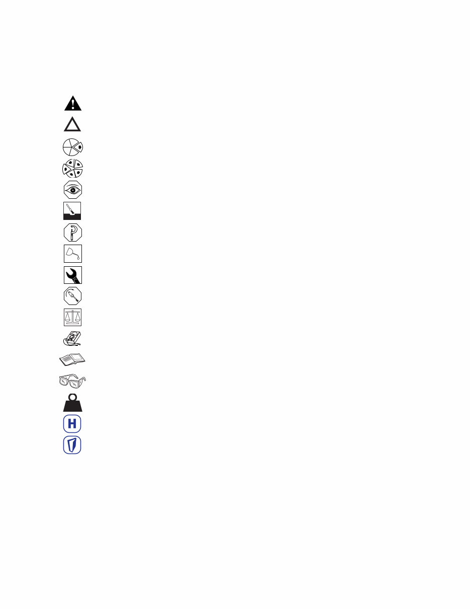
Symbole - Deutsch
In diesem Handbuch werden die folgenden Symbole verwendet, die wesentliche Funktionen hervorheben. Die
Symbole haben folgende Bedeutung:
WARNUNG - Unterhaltungs und Wartungsverfahren müssen genau befolgt werden, da ein
Nichtbeachten zu Personenschäden oder tödlichen Verletzungen führt.
ACHTUNG - Falls Unterhaltungs und Wartungsverfahren nicht genau beachtet werden, kann der
Turbolader dadurch beschädigt oder zerstört werden.
AUSBAU bzw. ZERLEGEN.
EINBAU bzw. ZUSAMMENBAU.
INSRPEKTION erforderlich.
Teil oder Baugruppe REINIGEN.
DIMENSION - oder ZEITMESSUNG.
Teil oder Baugruppe ÖLEN.
WERKZEUGGRÖSSE wird angegeben.
ANZUG auf vorgeschriebenes Drehmoment erforderlich.
Sicherstellen, daß die AUSWUCHTMARKEN an der Rotor-Baugruppe richtig ausgerichtet sind.
Elektrische MESSUNG DURCHFÜRHREN.
Weitere Informationen an anderer Stelle bzw. in anderen Handbüchern.
Schutzkleidung muß immer getragen werden.
Deutet an, daß Teile schwer sein können.
Website-Verzeichnis mit Ihrem nächsten Holset-Händler.
Gehe zu Inhalt
WH2D Service Repair Manual Introduction
Symbols
1:6
KG
WH2D Service Repair Manual Introduction
1:7
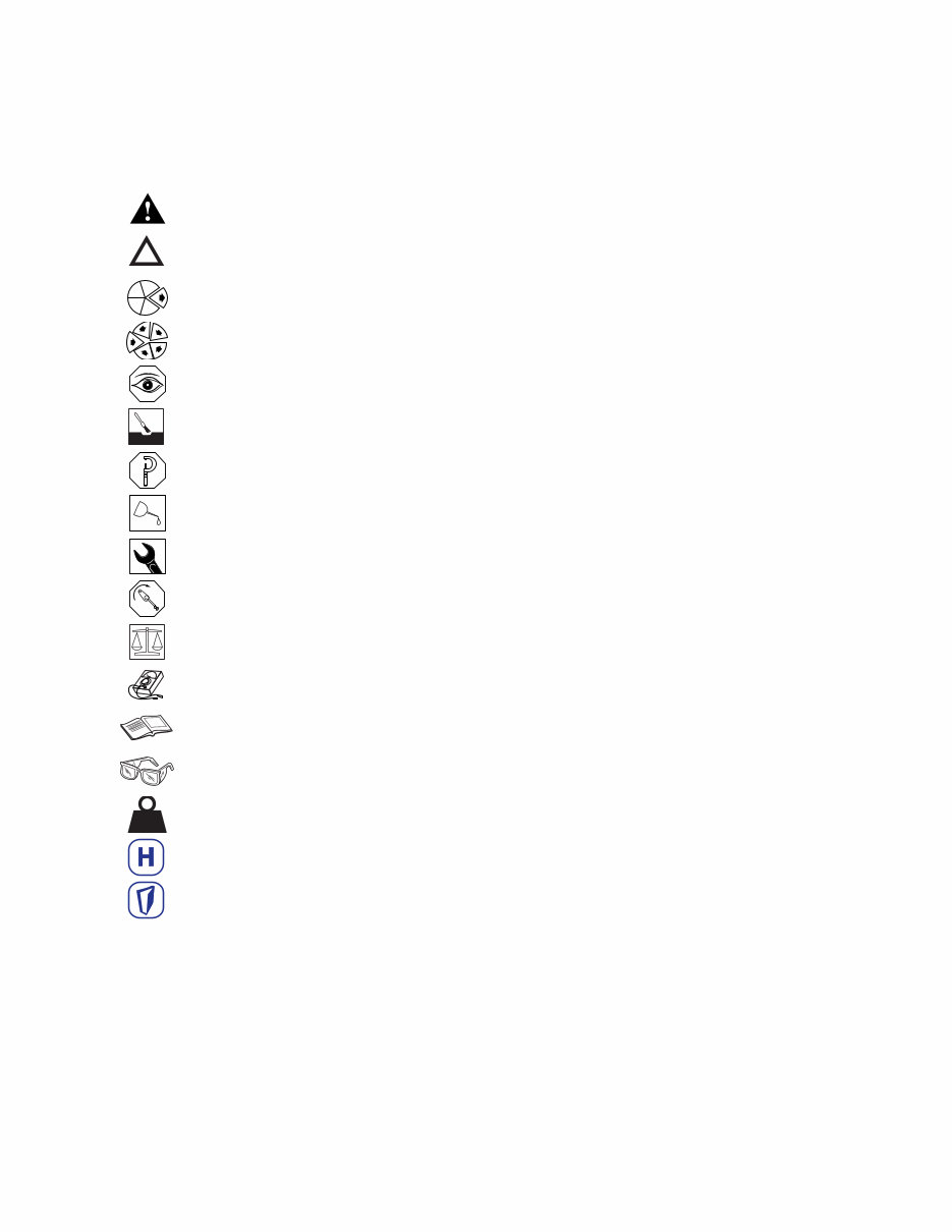
Symbols - English
The following group of symbols have been used in this manual to help communicate the intent of the
instructions. When one of the symbols appears, it conveys the meaning defined below.
WARNING - Serious personal injury or extensive property damage can result if the warning
instructions are not followed.
CAUTION - Minor personal injury can result or a part, an assembly or the engine can be damaged if
the caution instructions are not followed.
Indicates a REMOVAL or DISASSEMBLY step.
Indicates an INSTALLATION or ASSEMBLY step.
INSPECTION is required.
CLEAN the part or assembly.
PERFORM a mechanical or time MEASUREMENT.
LUBRICATE the part or assembly.
Indicates that a WRENCH or TOOL SIZE will be given.
TIGHTEN to a specific torque.
Ensure that the BALANCE MARKS on the rotor assembly are in alignment
PERFORM an electrical MEASUREMENT.
Refer to another location in this manual or another publication for additional information.
Please wear protective clothing at all times.
Indicates components may be heavy.
Website access to find your nearest Holset Agent.
Go to contents
KG
You're Reading a Preview
What's Included?
Fast Download Speeds
Offline Viewing
Access Contents & Bookmarks
Full Search Facility
Print one or all pages of your manual
$52.99
Viewed 52 Times Today


Secure transaction
What's Included?
Fast Download Speeds
Offline Viewing
Access Contents & Bookmarks
Full Search Facility
Print one or all pages of your manual
$52.99
The Holset Turbochargers OEM Service & Repair Manual covers the following models:
- H1C_D_E_H2A
- H2B_C_D_E_S
- HE-service-data-sheet
- HE221W
- HE300W
- HE341Ve
- HE351CW
- HE431V
- HE551V
- HE851
- HX20W
- HX25_25W_27W
- HX30_32_35_38_40_GW
- HX30_32_35_40
- HX50W_55W
- HX50_52_55
- HX55V
- HX60W_HT60W
- HX60_HT60
- HX80_85
- HX_Service_Data_Sheet
- HY30W
- HY35W
- HY40V-iveco
- HY55V-worldwide
- HY55V
- H_Service_Data_Sheet
- HolsetTurboTroubleshooting
- HolsetTurbos_FailureDiagnosis
- Pre-H_Service_Data_Sheet
- VG_Service_Data_Sheet
- WH1C_E
- WH2D
- holsetturbo_productionspecs
This comprehensive OEM manual provides detailed guidance for turbocharger installation, maintenance, and overhaul. It is designed for professional mechanics as well as DIY enthusiasts, presenting up-to-date technical specifications, procedural instructions, and model-specific data for the entire range of Holset turbochargers.
Please note that all information in this manual is based on the latest available data, ensuring accuracy in the repair and service procedures. It is recommended to use genuine Holset parts for replacements. For any access-related issues or inquiries, please contact Cummins Turbo Technologies via email.


