ZF Marine Transmissions/Gearboxes (ZF3M/ZF5M/ZF10M/ZF12M/ZF15M/ZF15MA/ZF15MIV/ZF25M/ZF25MA/ZF30M) OEM Service & Repair Manual
What's Included?
Lifetime Access
Fast Download Speeds
Online & Offline Access
Access PDF Contents & Bookmarks
Full Search Facility
Print one or all pages of your manual
SERVICE MANUAL AND SPARE PARTS LIST SERVICE MANUAL AND SPARE PARTS LIST Cod. 310.01.0052f R E P A I R M A N U A L ZF 3 M (HBW 35) ZF 5 M (HBW 50) ZF 10 M (HBW 100) ZF 12 M (HBW 125) / HBW 10 ZF 15 M (HBW 150) ZF 15 MA (HBW 150 A) ZF 15 MIV (HBW 150 V) ZF 25 M (HBW 250) ZF 25 MA ZF 30 M
Manual and Spare Parts List ZF M line 3 This ZF M manual has been prepared for all those who have to do with ZF- HURTH Marine reversing gearbox units of the ZF M line, including models ZF 3 M, ZF 5 M, ZF 10 M, ZF 12 M, ZF 15 M, ZF 15 MA, ZF 25 M, ZF 25 MA, ZF 30 M, ZF 15 MIV, in particular for - power plant suppliers - shipyards - craft owners The ZF M manual is intended as an aid for handling ZF M transmissions and will answer all questions that may arise in daily operation and in connection with the installation and repair of ZF M transmis- sions. This manual contains: - Technical description of the gearbox units and a number of important tech- nical data; - Instructions for proper installation of the gearbox in the craft; - Explanatory notes on correct operation and maintenance; - Detailed description of all disassembly and reassembly procedures (with drawings); - Troubleshooting table with possible causes of trouble and the required re- medial action; - Spare parts list with stock numbers of all sparte parts; - Explosion-View drawings showing each part with the reference numerals used in the text. No problems will be encountered in han- dling, installing and operating the ZF M gearbox if the instructions in this manual are followed. Should a repair be neces- sary, a qualified technician will have no difficulty in doing the repair work in ac- cordance with the detailed instructions given on the following pages. In addition, ZF M Service Stations (dis- tributors and dealers) are available for any repairs and for supplying the spare parts required. The manufacturer will al- ways be glad to name the Service Sta- tion nearest to your location. All transmission units are covered by a worldwide guarantee given by the manu- facturer. The manufacturer’s warranty will be subject to the condition that: - the instructions in this manual are strictly observed in handling the transmission. - no work is performed by persons not authorized by ZF-HURTH Marine. - no changes or alterations of any kind are made on the transmission. Failure to observe these points will invalide all and any warranty claims. Caution: never start doing any work on the transmission unless and until the engine and the propeller have come to a complete standstill.
Manual and Spare Parts List ZF M line 4 Table of contents 1. Description 1.1 Brief description 1.2 Technical data and main dimensions 1.2.1 ZF 3 M boat reversing gearbox unit 1.2.2 ZF 5 M boat reversing gearbox unit 1.2.3 ZF 10 M boat reversing gearbox unit 1.2.4 ZF 12 M boat reversing gearbox unit 1.2.5 ZF 15 M boat reversing gearbox unit 1.2.6 ZF 15 MA boat reversing gearbox unit 1.2.7 ZF 15 MIV boat reversing gearbox unit 1.2.8 ZF 25 M boat reversing gearbox unit 1.2.9 ZF 25 MA boat reversing gearbox unit 1.2.10 Accessories 1.2.11 Tools 1.2.12 Ident. No. 1.3 Gear casing 1.4 Gear set 1.5 Multiple-disc clutch and clutch operation 1.6 Shaft bearings 1.7 Shaft seals 1,8 Lubrication 1.9 Cooling unit 2. Installation 2.1 Delivery condition 2.2 Transport 2.3 Removal of preservative 2.4 Painting the gearbox 2.5 Connection of gearbox with engine 2.6 Connection of gearbox with propeller 2.7 Suspension of engine- gearbox assembly in the boat 2.8 Position of gearbox in the boat 2.9 Operation of gearbox 2.10 Cooling unit 2.11 Engine-gearbox compartment 3. Operation 3.1 General information 3.2 Initial operation 3.3 Operating temperature 3.4 Operation of gearbox 3.5 Sailing or moving in tow 3.6 Lay-up periods 3.7 Preparation for re-use 4. Maintenance 4.1 Transmission oil 4.2 Oil quantity 4.3 Oil level checks 4.4 Oil change 4.5 Checking the shift cable and linkage 4.6 Cooling unit 4.7 Automatic transmission fluiid List of recommended fluids 5. Disassembly 5.1 Removing the cooling unit 5.2 Removing and disassembling the actuating lever cover plate 5.3 Removing the bearing shields 5.4 Separating the gearbox sections and removing the input and output shafts 5.5 Removing the shifting fork 5.6 Removing the intermediate gear 5.7 Disassembling the input shaft 5.8 Disassembling the output shaft 5.9 Disassembling the quill shaft 6. Reassembly 6.1 General information 6.2 Pre-assembling the intermediate gear shaft in the gearbox section without opening 6.3 Pre-assembling the shifting fork in the gearbox section with opening 6.4 Pre-assembling the actuating lever cover plate 6.5 Pre-assembling the gears 6.6 Measuring the pre-assembled gears to determine setting value «a» 6.7 Pre-assembling the bearing shields 6.8 Pre-assembling the actuating members 6.9 Reassembling the input shaft 6.10 Reassembling the output shaft 6.11 Reassembling the quill shaft 6.12 Final assembly of gearbox 6.13 Measuring the gear sets of input shaft and output shaft 6.14 Mounting the actuating lever cover plate 6.15 Mounting the cooling unit 7. Procedure to adjust the shifting lever cover 8. Troubleshooting 9. Spare parts list 10. Drawings (Explosion view)
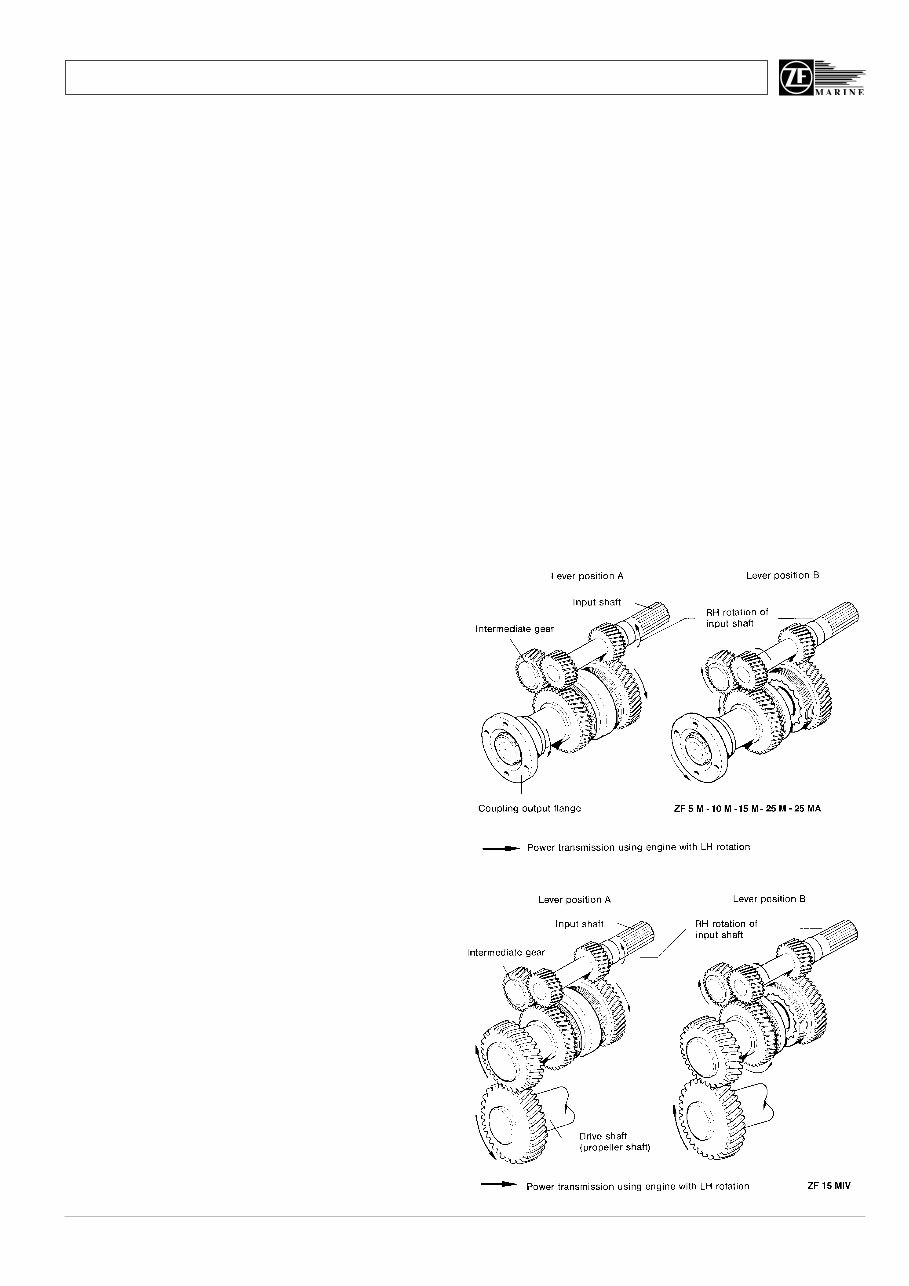
Manual and Spare Parts List ZF M line 5 1. Description 1.1 Brief description ZF-HURTH Marine boat reversing gear- box units of the ZF M line are servo-au- tomatically controlled helical gear trans- missions developed for use in pleasure craft and commercial craft. The servo- operated multiple-disc clutch requires only minimum effort for shifting, making the ZF M transmission suitable for single-lever remote control via a rod linkage or shift cable. In emergency situations the ZF M per- mits direct reversing at engine speed above idle rpm. The torque capacity of the clutch is ex- actly rated, preventing shock loads from exceeding a predetermined value to en- sure maximum protection of the engine and thus providing the effect of a safety clutch. The transmission units are characterized by low weight and small overall dimen- sions. The gearbox castings are made of a high-strength, corrosion-resistant aluminium alloy, chromized for improved seawater resistance and optimum adhesion of paint. A choice of gear ratios, a high efficiency rating and low-noise operation are other prominent features of the ZF M gearbox units. The transmissions are immersion-lubri- cated. Maintenance is restricted to oil level checks (see «Maintenance», chap- ter 4). The shafts are supported by heavy-duty taper roller bearings and the gearbox is designed to take the axial propeller thrust (for permissible values see «Technical data», item 1.2). Transmission sizes are available for right-hand (RH) and left-hand (LH) rotation of the input shaft, the direction of rotation being specified as seen by an observer facing the input shaft. In gear lever positions A, the engine shaft and the propeller shaft rotate in oppo- site directions, in position B in the same direction (Fig. 1). On model ZF 15 MIV, the directions of rotation are the other way round (Fig. 2). Engine manufacturers should note that the direction of rotation refers to an ob- server facing the flywheel, so that left- hand rotation of the engine corresponds to right-hand rotation of the gearbox in- put shaft. Fig. 1 Fig. 2
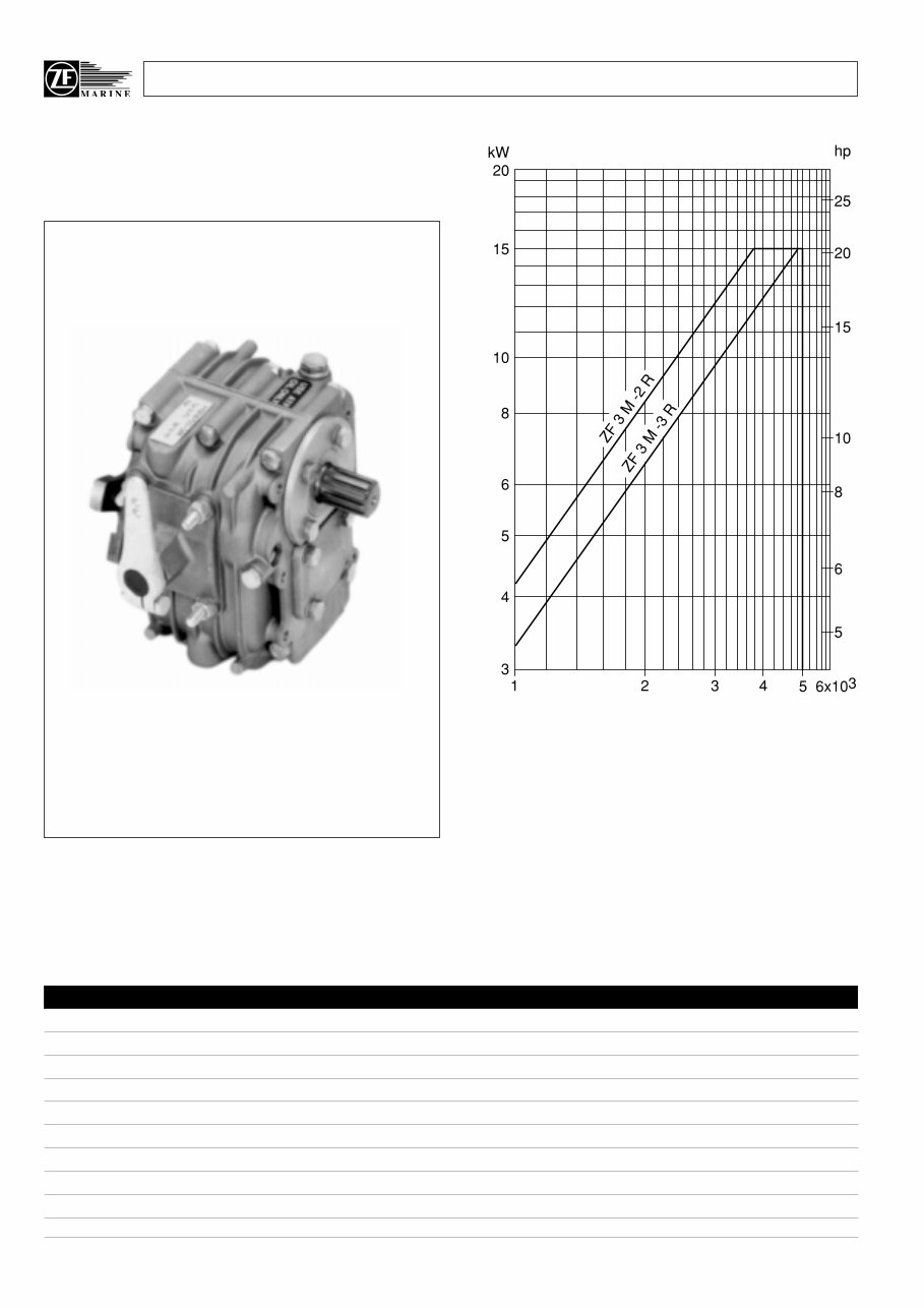
Manual and Spare Parts List ZF M line 6 1.2.1 ZF 3 M Power diagram Based on engine power B to DIN 6270; shock factor K = 1.25 to applied, if engine has 1 cylinder K = 1.20 for 2 cylinders K = 1.15 for 3 cylinders Transmission input speed (rpm) Transmission power input Technical data ZF 3 M-2 R ZF 3 M-3 R Shifting position «A» ratio 2.05:1 2.72:1 Shifting position «B» ratio 1.86:1 2.15:1 Input torque max. Nm (ft lb) 40 (29,5) 30 (22,1) Power input max. kW (hp) 15 (20) Input speed max. rpm 5000 Propeller thrust max. N (lb) 1000 (225) Weight without fluid kg (lb) 8 (17.7) Fluid quantity liter 0.3 Fluid grade Automatic-Transmission-Fluid (ATF)
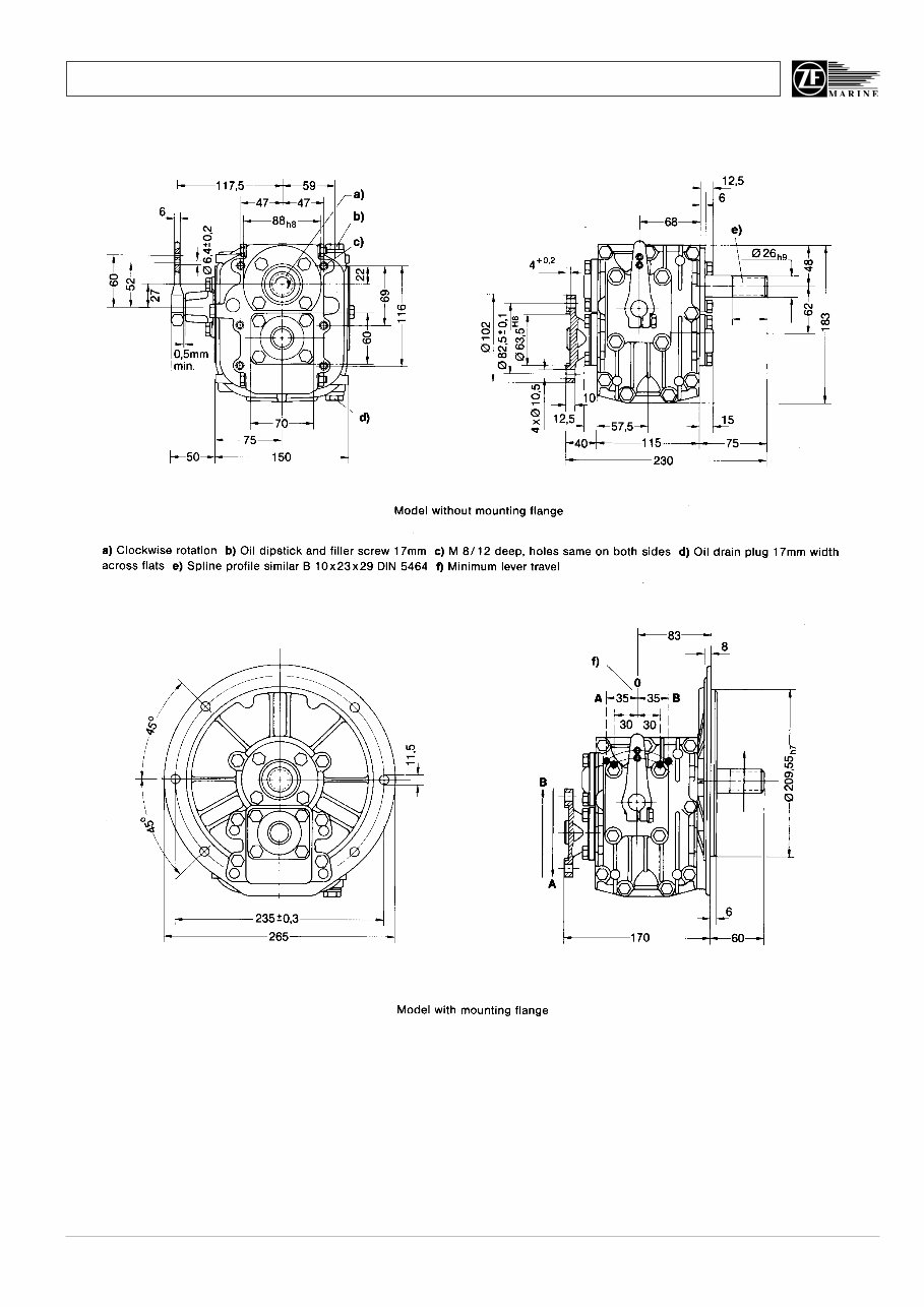
Manual and Spare Parts List ZF M line 7 All dimensions in mm Fig. 3 ZF 3 M 54
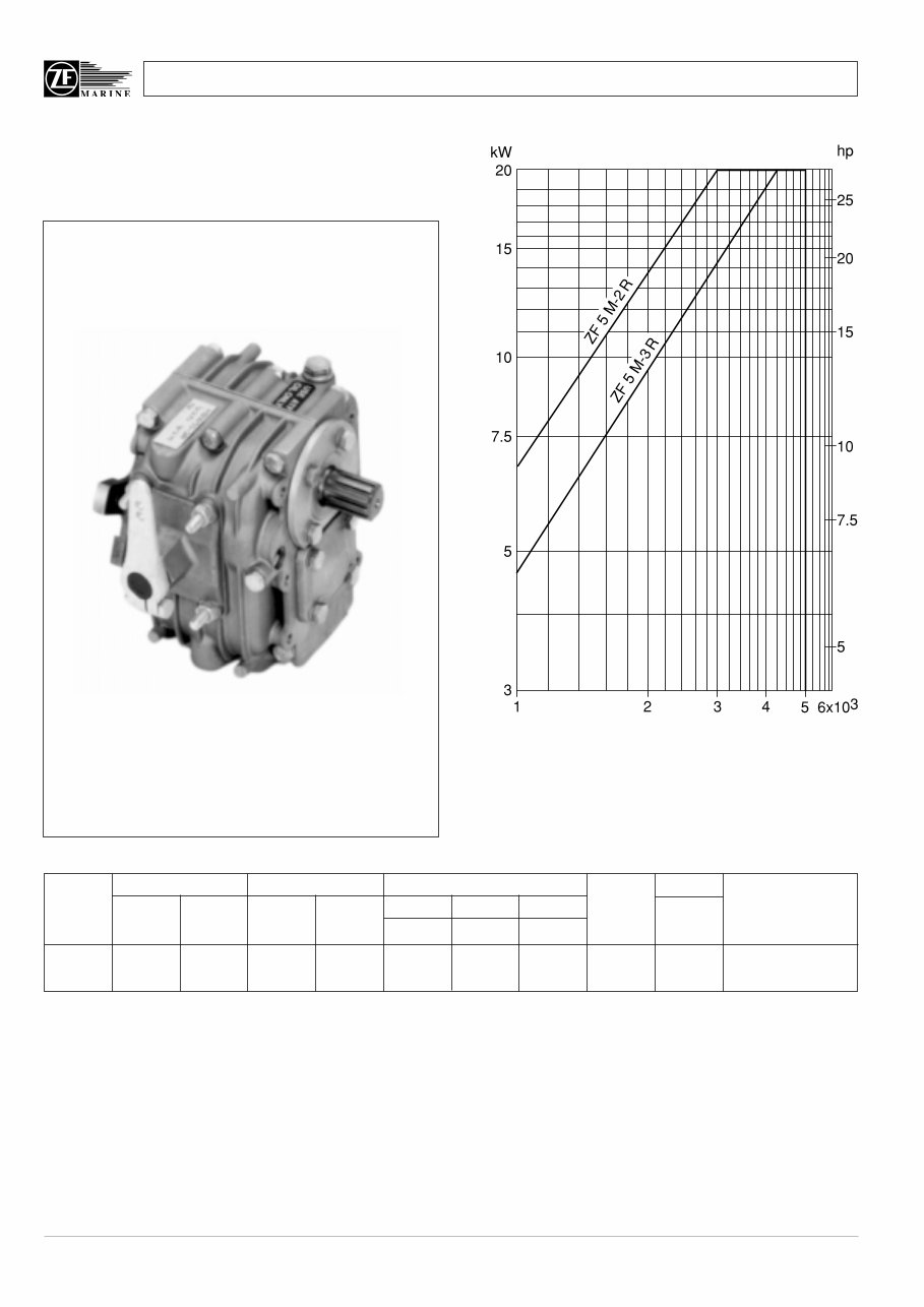
Manual and Spare Parts List ZF M line 8 1.2.2 ZF 5 M Power diagram for Pleasure Craft Duty Based on engine power B to DIN 6270; shock factor K = 1.25 to applied, if engine has 1 cylinder K = 1.20 for 2 cylinders K = 1.15 for 3 cylinders Transmission power input ZF 5 M 2.045 1.864 0.0066 0.0088 18 25 20 27 20 27 5000 8 18 B/W 2.722 2.150 0.0047 0.0063 13 18 14 19 17 23 5000 Max input power 15 kW MODEL RATIO POWER / RPM INPUT POWER CAPACITY MAX WEIGHT BELL HSGS. «A» Pos «B»Pos kW hp kW hp kW hp kW hp RPM kg lb AND NOTES 2800 rpm 3000 rpm 3600 rpm «A» POS = continuous running position (normally AHEAD). «B» POS = reverse position. B/W = Borg Warner adaptor. Note = For all «M» (Mechanical) transmission reduce power capacity by the following schock factors: 1 cylinder engine ÷ 1.25, 2 cylinder engine ÷ 1.20, 3 cylinder engine ÷ 1.15.
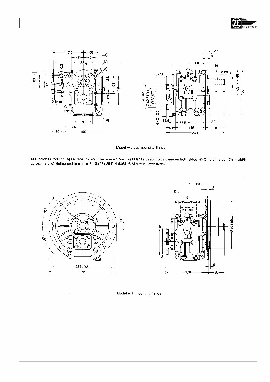
Manual and Spare Parts List ZF M line 9 Fig. 4 ZF 5 M All dimensions in mm 54
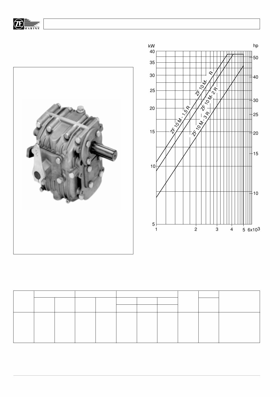
Manual and Spare Parts List ZF M line 10 ** Max. 95 Nm (70 ft lb) admissible for main travelling direction with gear lever set to «B» 1.2.3 ZF 10 M Power diagram for Pleasure Craft Duty Based on engine power B to DIN 6270; shock factor K = 1.25 to applied, if engine has 1 cylinder K = 1.20 for 2 cylinders K = 1.15 for 3 cylinders Transmission input speed (rpm) Transmission power input 1,8 MODEL RATIO POWER / RPM INPUT POWER CAPACITY MAX WEIGHT BELL HSGS. «A» Pos «B»Pos kW hp kW hp kW hp kW hp RPM kg lb AND NOTES 2800 rpm 3000 rpm 3600 rpm ZF 10 M 1.482 1.864 0.0109 0.0146 30 41 33 44 38 51 5000 9.5 21 SAE 4, 5, B/W 1.792 1.864 Max input power 38 kW. 2.045 1.864 0.0095 0.0128 27 36 29 38 34 46 5000 Ratio 1.482 «B» Pos. 2.722 2.150 0.0068 0.0091 19 26 20 27 25 33 5000 max torque 95 Nm. Ratio 1.792 «B» Pos. max torque 95 Nm. «A» POS = continuous running position (normally AHEAD). «B» POS = reverse position. B/W = Borg Warner adaptor. Note = For all «M» (Mechanical) transmission reduce power capacity by the following schock factors: 1 cylinder engine ÷ 1.25, 2 cylinder engine ÷ 1.20, 3 cylinder engine ÷ 1.15.
ZF Marine Transmissions/Gearboxes Service & Repair Manual is a comprehensive technical resource covering various models, including ZF 3 M (HBW 35), ZF 5 M (HBW 50), ZF 10 M (HBW 100), ZF 12 M (HBW 125) / HBW 10, ZF 15 M (HBW 150), ZF 15 MA (HBW 150 A), ZF 15 MIV (HBW 150 V), ZF 25 M (HBW 250), ZF 25 MA, and ZF 30 M.
This manual provides detailed service, maintenance, troubleshooting, and replacement procedures for the transmissions. It includes step-by-step instructions, clear images, and exploded-view illustrations, making it suitable for professional mechanics and DIY enthusiasts.
Please note that this is not a generic repair manual but the manufacturer-sourced OEM manual used by professional technicians. It contains comprehensive troubleshooting and replacement procedures, along with clear images and exploded-view illustrations.
With this digital manual, there's no need to search through numerous pages or worry about damaged physical copies. It is easily accessible, searchable, and can be used on various electronic devices, including PCs, Mac computers, smartphones, and tablets.
The manual is available in English and can be printed if a physical copy is preferred. It is compatible with Adobe Reader, which is available for free.
Recently Viewed
5,521,897Happy Clients
2,594,462eManuals
1,120,453Trusted Sellers
15Years in Business
Price:
Actual Price:
ZF Marine Transmissions/Gearboxes (ZF3M/ZF5M/ZF10M/ZF12M/ZF15M/ZF15MA/ZF15MIV/ZF25M/ZF25MA/ZF30M) OEM Service & Repair Manual