

ZF Transmission S6-650 6-Speed Service & Repair Manual
What's Included?
Fast Download Speeds
Online & Offline Access
Access PDF Contents & Bookmarks
Full Search Facility
Print one or all pages of your manual

ZF Industries, Inc. S6-650 Six Speed
Manual Transmission
Vehicle Transmission Technology Service Manual
Author: Michael S. Paterson Page 1 of 48 GM Service Manual 08/05/03
Disassembly and assembly of subassemblies:
1. S6-650 Disassembly……………………………………….……page 2 - 8
2. Input Shaft Disassembly………………………….………….… page 9
3. Main Shaft Disassembly………………………………….……..page 10 - 11
4. Counter Shaft Disassembly………………………..……….…...page 12
5. Extension Housing………………………………………………page 13 -15
6. Case…………………………………………………….…..……page 16 -17
7. Assembly………………...………………………………………page 18 - 19
8. Input Shaft Assembly……………………………………………page 20
9. Counter Shaft Assembly………………………………...………page 21
10. Main Shaft Assembly……………………………………...……page 22 - 26
11. Subassembly Final Assembly…………………………..………page 27 - 39
12. Specifications………………………………………….……….page 40 - 41
13. Tool List…………………………………………….………….page 42 - 48
ZF Industries, Inc. S6-650 Six Speed
Manual Transmission
Vehicle Transmission Technology Service Manual
Author: Michael S. Paterson Page 2 of 48 GM Service Manual 08/05/03
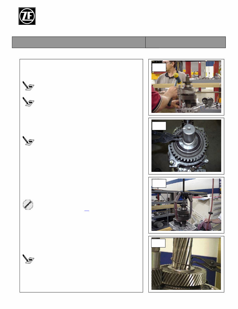
1. S6-650 Disassembly
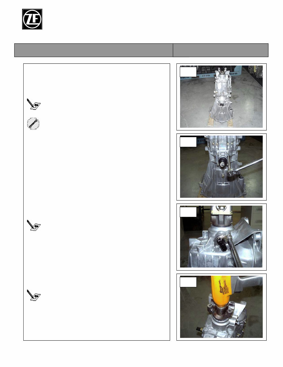
1. Position the transmission on the floor with the
output flange pointing up. Block up the housing to
allow room for the input shaft.
If you are working on a seal leak, the unit can be
repaired while it is still assembled.
For this step, use numbers 14(output),33(input) and 20
on the Tool List.
2. Remove the four 6mm Allen bolts and remove the
shifter.
3. Remove the 10mm bolt and speed sensor.
Step 1.3 and 1.4 is performed on the 4x2 model only.
4. Remove the output flange nut and the output flange.
Failure of the power take-off equipment will not be
covered under the O.E. warranty and should not be
coded as a transmission failure.
1.1
1.2
1.3
1.4
ZF Industries, Inc. S6-650 Six Speed
Manual Transmission
Vehicle Transmission Technology Service Manual
Author: Michael S. Paterson Page 3 of 48 GM Service Manual 08/05/03
1. S6-650 Disassembly (cont.)
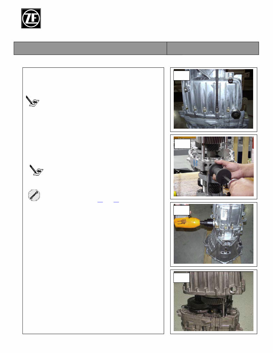
5. Remove the nineteen 10mm extension housing to
intermediate housing bolts.
Mark the position of the wiring harness bracket.
6. Remove the four 14mm detent caps using the slide
hammer and oil seal remover, then the four springs.
Leave the detent plungers in the housing unless they
are damaged.
Use a center punch to start a small hole in the detent
before using the slide hammer and the oil seal
remover.
For this step, use number 14 and 20 on the Tool List.
7. Remove the 1 5/8” main shift detent.
8. Remove the extension housing using a rubber
hammer to separate the extension housing from the
intermediate housing.
1.5
1.6
1.7
1.8
ZF Industries, Inc. S6-650 Six Speed
Manual Transmission
Vehicle Transmission Technology Service Manual
Author: Michael S. Paterson Page 4 of 48 GM Service Manual 08/05/03
1. S6-650 Disassembly (cont.)
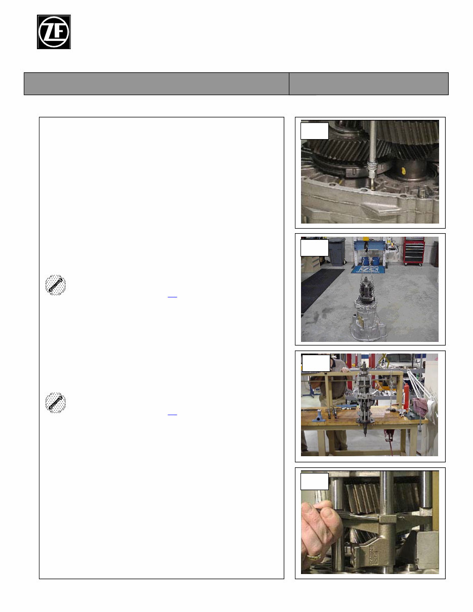
9. Remove the two 6mm Allen bolts from the
intermediate housing.
10. Using a chain and hooks, carefully lift the
intermediate housing assembly out of the main
housing.
For this step, use number 13 on the Tool List.
11. Position the main shaft /counter shaft assembly on
the holding plate that has been mounted to a sturdy
workbench.
For this step, use number 24 on the Tool List.
12. Using a hammer and punch, remove the main shift
rail driver roll pin.
1.12
1.11
1.10
1.9
ZF Industries, Inc. S6-650 Six Speed
Manual Transmission
Vehicle Transmission Technology Service Manual
Author: Michael S. Paterson Page 5 of 48 GM Service Manual 08/05/03
1. S6-650 Disassembly (cont.)
13. Using a hammer and punch, remove the 2 / 3 – 4 /
5 rail driver roll pin, located on the lower section of
the main shift rail.
14. Remove the main shift rail.
Do not force the shaft or it will cause damage to the
ball sleeve in the intermediate housing.
15. Remove the sixth gear roll pins.
16. Remove the sixth gearshift rail by lightly tapping
the sixth gearshift fork with a rubber hammer while
pulling up on the shift rail.
Check that the interlock plate is in the sixth gear
position before removing the sixth gear rail.
17. Using a hammer and a punch, remove the roll pins
from the first/reverse shift fork.
All shift forks must be inspected for wear. If they are
worn through the molly coating, they must be
replaced.
1.17
1.16
1.15
1.13
ZF Industries, Inc. S6-650 Six Speed
Manual Transmission
Vehicle Transmission Technology Service Manual
Author: Michael S. Paterson Page 6 of 48 GM Service Manual 08/05/03
1. S6-650 Disassembly (cont.)
18. Lightly tap the first/reverse shift fork with a rubber
hammer while pulling up on the shift rail.
Check that the interlock plate is in the first/reverse
position before removing the first/reverse shift rail.
Step 1.19 is performed on the 4x4 model only.
19. Using a pair of snap ring pliers, remove the snap
ring
Always discard the snap ring, it will distort when it is
removed. This is a selective snap ring.
20. Using a 2-jaw puller, remove the tone wheel, main
shaft bearing, first/reverse gears, synchronizer
assembly, and needle bearing.
For this step, use number 16 on the Tool List.
21. Remove the sixth gear, snap ring, needle bearing,
synchronizer assembly and thrust washer.
Always discard the snap ring, it will distort when it is
removed. This is a selective snap ring.
1.21
1.20
1.19
1.18
ZF Industries, Inc. S6-650 Six Speed
Manual Transmission
Vehicle Transmission Technology Service Manual
Author: Michael S. Paterson Page 7 of 48 GM Service Manual 08/05/03
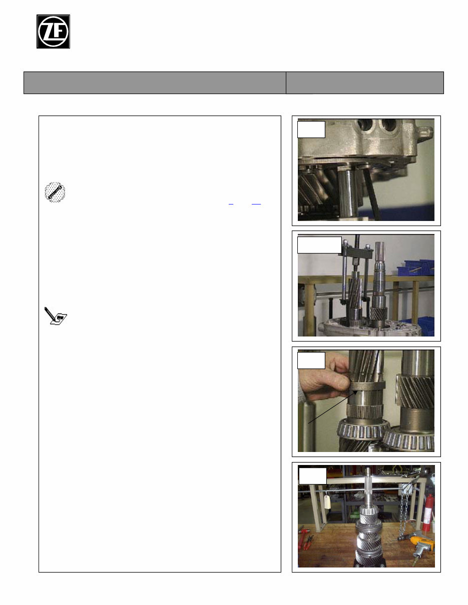
1. S6-650 Disassembly (cont.)
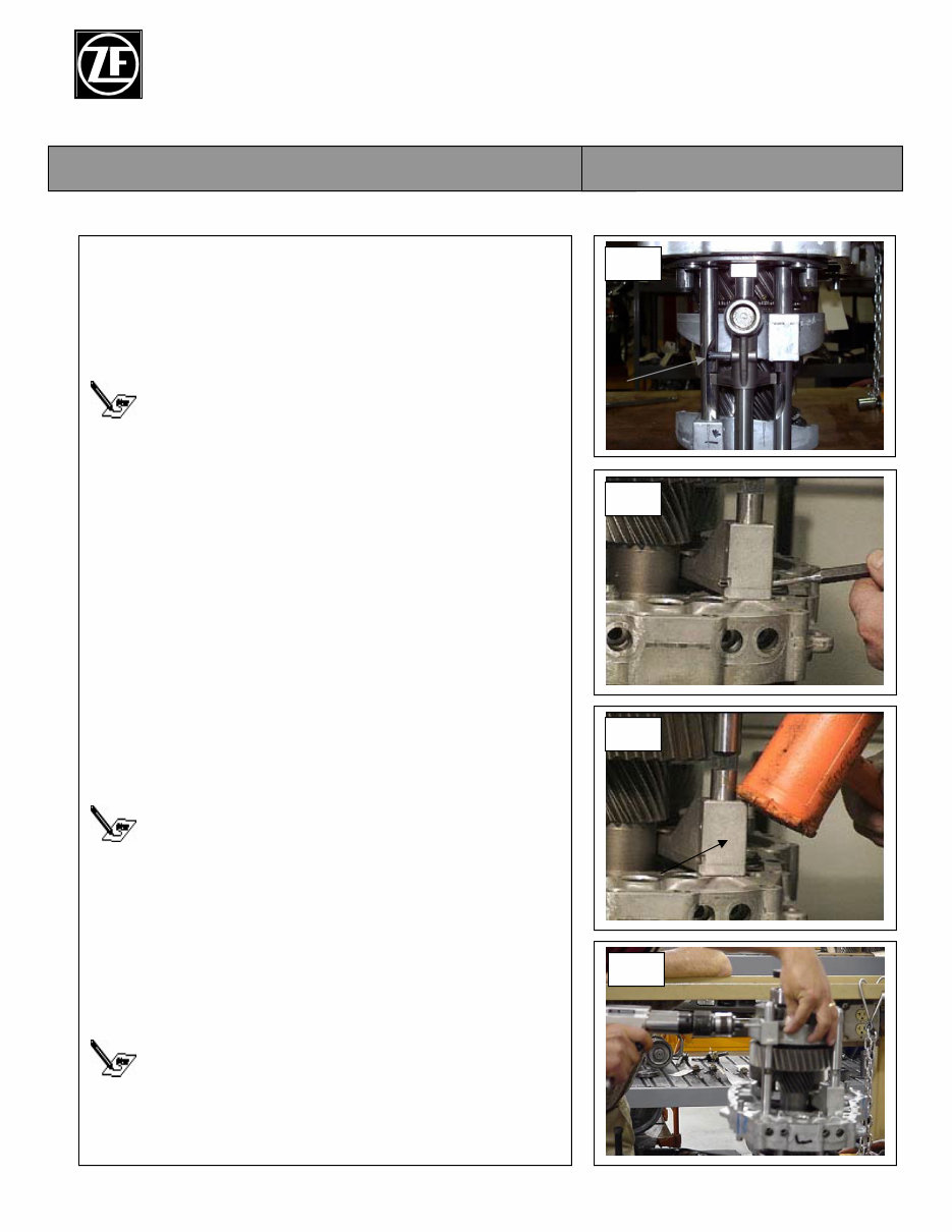
22. Remove the three 5mm collar screws from the
interlock plate.
23. Install the driver into the lifting fixture.
For steps 1.23,1.24 and 1.25, use numbers 1 and 15 on
the Tool List.
24. Mount the lifting fixture onto the counter shaft and
intermediate housing.
25. Using the lifting fixture, pull the intermediate
housing up to remove the sixth gear synchronizer
assembly and bearing race.
Check that the 2 / 3-4 /5 shift rails are not binding
while pulling the intermediate housing.
26. Remove the interlock plate and the 2 /3-4 / 5 shift
fork assemblies.
27. Remove the sixth gear spacer ring.
28. Position the main shaft assembly onto the
mounting plate with the input shaft in the upright
position.
1.28
1.27
1.23, 25
1.22
ZF Industries, Inc. S6-650 Six Speed
Manual Transmission
Vehicle Transmission Technology Service Manual
Author: Michael S. Paterson Page 8 of 48 GM Service Manual 08/05/03
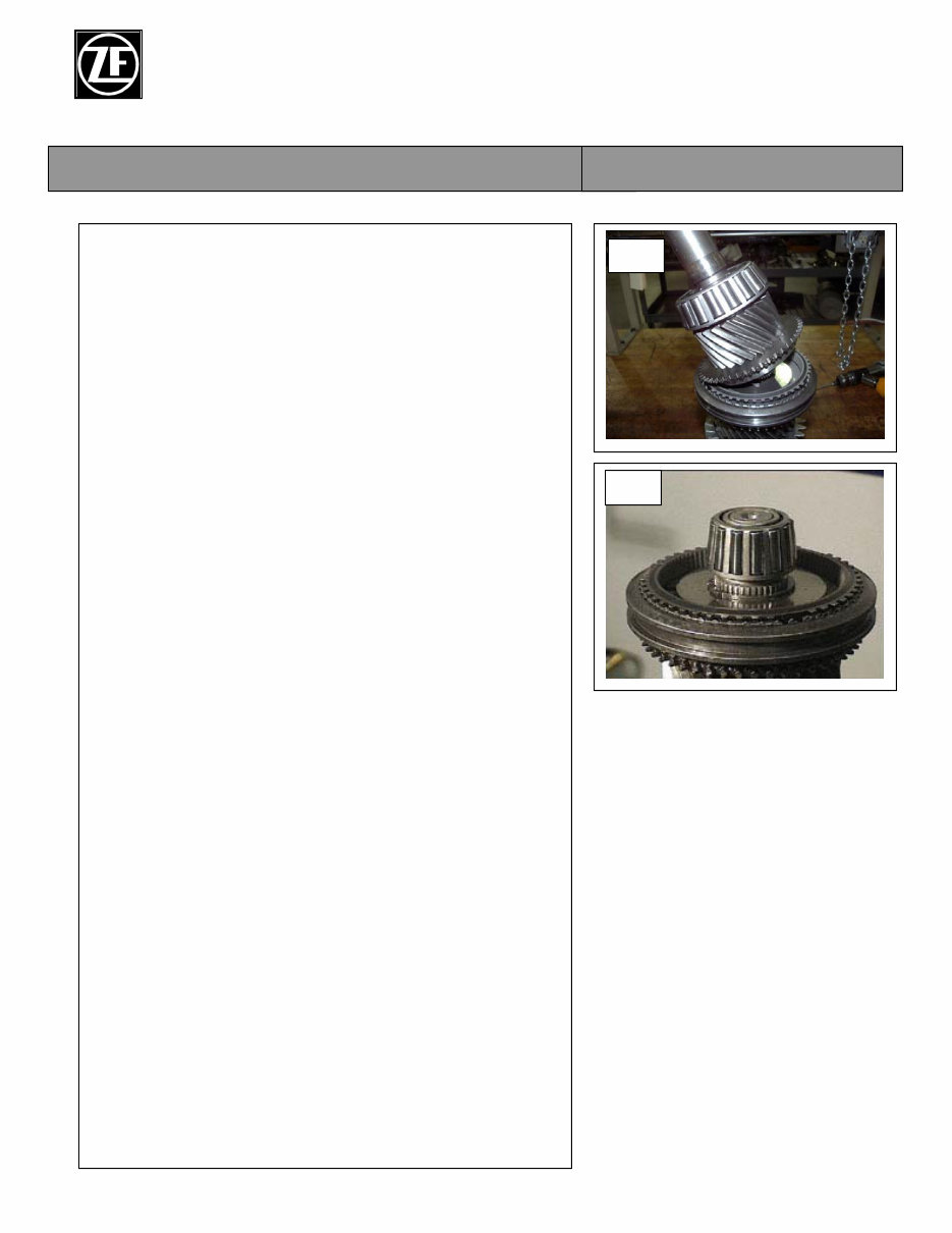
2. S6-650 Disassembly (cont.)
29. Remove the input shaft from the main shaft
assembly.
1.29
1.29
ZF Industries, Inc. S6-650 Six Speed
Manual Transmission
Vehicle Transmission Technology Service Manual
Author: Michael S. Paterson Page 9 of 48 GM Service Manual 08/05/03
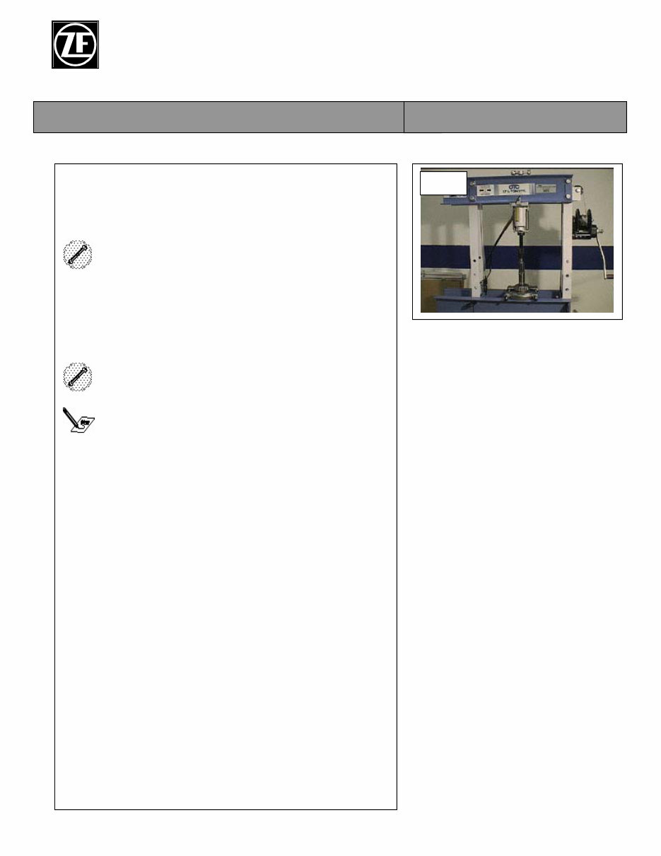
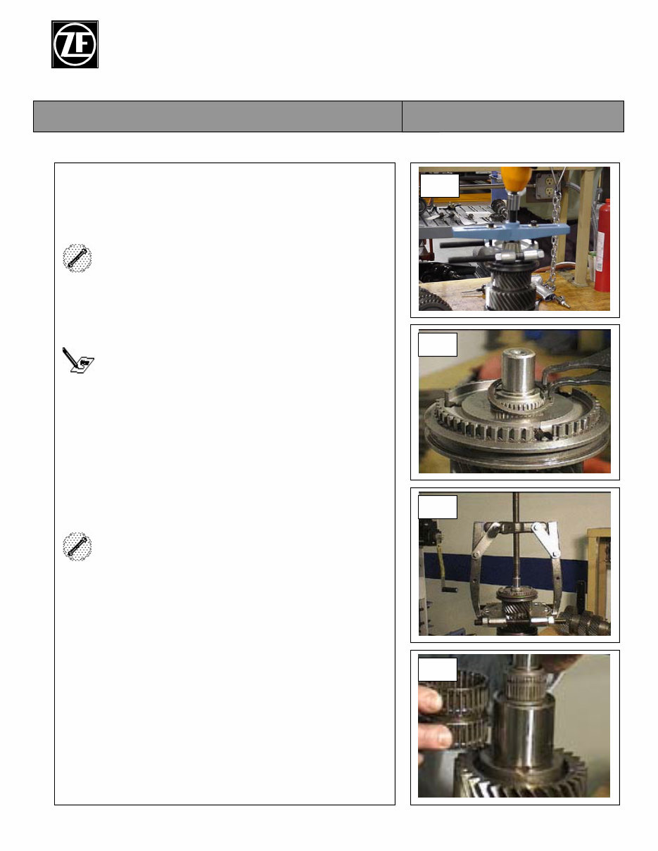
2. Disassembly and assembly of
subassemblies: input shaft disassembly.
1. Position the input shaft in the split puller.
For this step, use number 25 on the Tool List.
2. Using a two jaw puller or press, remove the input
shaft bearing.
For this step, use numbers 16 and 28 on the tool List.
Never reuse a bearing that has been removed in this
manner.
2.1, 2
ZF Industries, Inc. S6-650 Six Speed
Manual Transmission
Vehicle Transmission Technology Service Manual
Author: Michael S. Paterson Page 10 of 48 GM Service Manual 08/05/03
3. Disassembly and assembly of subassemblies:
main shaft disassembly.
1. Using the bearing puller and pulley puller remove
the pocket bearing.
For this step, use numbers 18 and 19 on the Tool
List.
2. Remove the 4 / 5 synchronizer hub snap ring.
Always discard the snap ring, it will distort when it is
removed. This is a selective snap ring.
3. Using the split puller and a two jaw puller, remove
the 4 / 5 synchronizer assembly and fouth gear.
For this step, use numbers 16 and 25 on the Tool List.
4. Remove the fourth gear needle bearing.
3.1
3.2
3.3
3.4
You're Reading a Preview
What's Included?
Fast Download Speeds
Online & Offline Access
Access PDF Contents & Bookmarks
Full Search Facility
Print one or all pages of your manual
$30.99
Viewed 75 Times Today


Secure transaction
What's Included?
Fast Download Speeds
Online & Offline Access
Access PDF Contents & Bookmarks
Full Search Facility
Print one or all pages of your manual
$30.99
- The ZF Transmission S6-650 6-Speed Service & Repair Manual offers comprehensive guidance for servicing and repairing the ZF S6-650 6-speed manual transmission.
- Designed for professionals and enthusiasts, it provides detailed technical information for addressing common and complex transmission issues.
- Includes step-by-step procedures, diagnostic charts, and clear illustrations for thorough understanding and accurate repairs.
- Covers disassembly, inspection, reassembly, torque specifications, and required tools.
- Supports effective troubleshooting and repair strategies to maintain transmission integrity and performance.
- Useful for both professional mechanics and DIY enthusiasts working with ZF's advanced transmission systems.
- Printable: Yes
- Language: English
- Compatibility: Compatible with various electronic devices including PC, Mac, Android, and Apple smartphones and tablets.
- Requirements: Adobe Reader (free)


