


Order no.: 5871 977 002
ZF - TRACTOR TRANSMISSION
ECCOM 1.5
(SDFG SERIES 20)
REPAIR LEVEL III
ZF Passau GmbH
Donaustr. 25 - 71
D- 94034 Passau

REPAIR MANUAL
for
ZF – TRACTOR TRANSMISSION
ECCOM 1.5
I M P O R T A N T I N F O R M A T I O N :
Due to the great variety of ZF units it is necessary to limit disassembly and reassembly manuals to a
current ZF production unit. Continuous technical upgrading of the ZF units and extensions
concerning design options may require differing steps, which can be carried out by qualified
specialists without greater difficulties by means of the perspective views included in the
corresponding spare parts lists.
This disassembly and reassembly manual is based on the design level of a ZF production unit at the
time of issue of the manual.
ZF Passau GmbH reserves the right to replace this disassembly and reassembly manual by a
successive edition at any time without advance notice. Upon request, ZF Passau GmbH will advise
which edition is the latest one.
ACHTUNG:
Observe the vehicle manufacturer’s instructions and specifications for the
installation and commissioning of the unit!
For information on operation, maintenance and for descriptions please refer to the
corresponding ZF-Operation Manual.
ZF Passau GmbH
Donaustr. 25 - 71
D- 94034 Passau
Abt. : ASDM / Division : ASDM
Nachdruck auch auszugsweise ohne die Genehmigung der ZF Passau GmbH nicht gestattet!
Copyright ZF Passau GmbH! Complete or partial reproduction is not permitted!
Copyright ZF Passau GmbH! Toute reproduction, même partielle, est interdite!
Technische Änderungen vorbehalten!
Subject to technical modifications!
Sous réserve de modifications techniques!
Konstruktionsstand / Design Level / Niveau Technique
1.Auflage / 1
st
Edition / 1ère Édition 2005/01

CONTENT
Chapter/page
Preface
General
Conversion table
Denomination of standard dimensions
Tightening torques for screws
0/1
0/2 … 3
0/4
0/5
0/6
SPECIAL TOOLS W/1 ... WB/15
List of tools (requested special tool)
ILLUSTRATED TABLES
W/1 ... 9
WB/1 ... 15
DISASSEMBLY 1/1 ... 4/23
1. Disassembly of components
1.1 Disassembly of the clutch control block
1.2 Disassembly of the system control block
1.3 Disassembly of the pump
2. Separation of the transmission halves
3. Disassembly of the intermediate housing
3.1 Disassembly of the front wheel drive
3.2 Disassembly of clutch (KV/KR) and double gear
3.2.1 Disassembly of clutch KV
3.2.2 Disassembly of clutch KR
3.3 Disassembly of the output gear
3.4 Disassembly of the input shaft (hydrostatic unit))
3.5 Disassembly of the central shaft (clutch KV/KR)
3.6 Disassembly of the intermediate gear
4. Disassembly of the clutch housing
4.1 Disassembly of the multi-disk brake (BG)
4.2 Disassembly of the drum selector gear (planetary transmission)
4.2.1 Disassembly of ring gear P4/BG
4.2.2 Disassembly of clutch K3/K4
4.2.3 Disassembly of planetary drive P4
4.2.4 Disassembly of the central shaft
4.2.5 Disassembly of clutch K1/K2
4.2.6 Disassembly of planetary drive P3
4.2.7 Disassembly of planetary drive P2
4.2.8 Disassembly of planetary drive P1
4.3 Disassembly of the hydrostatic unit
1/1 ... 6
1/1 … 3
1/4 ... 5
1/6
2/1 … 2
3/1 ... 17
3/1 ... 3
3/4 … 10
3/4 ... 7
3/7 ... 10
3/11 … 12
3/13 … 14
3/15
3/16 … 17
4/1 ... 23
4/1 ... 2
4/3 ... 18
4/3 … 4
4/4 … 6
4/7 … 8
4/8 … 9
4/10 … 13
4/13 … 15
4/15 … 17
4/17 … 18
4/19 ... 23

CONTENTS
Chapter / Page
REASSEMBLY 5/1 ... 8/12
5. Reassembly of the clutch housing
5.1 Reassembly of the hydrostatic unit
5.2 Reassembly of the drum selector gear (planetary transmission)
5.2.1 Reassembly of planetary drive P1
5.2.2 Reassembly of planetary drive P2
5.2.3 Reassembly of planetary drive P3
5.2.4 Reassembly of clutch K1/K2
5.2.5 Reassembly of the central shaft
5.2.6 Reassembly of planetary drive P4
5.2.7 Reassembly of clutch K3/K4
5.3 Reassembly of the multi-disk brake (BG)
6. Reassembly of the intermediate housing
6.1 Reassembly of the input shaft (hydrostatic unit)
6.2 Reassembly of the intermediate gear
6.3 Reassembly of the central shaft (clutch KV/KR)
6.4 Reassembly of the output gear
6.5 Reassembly of the pump
6.6 Reassembly of clutch KV/KR
6.6.1 Reassembly of clutch KV
6.6.2 Reassembly of clutch KR
6.7 Reassembly of the front wheel drive
7. Joining of the preassembled transmission halves
7.1 Setting of the axial play drum selector gear/hollow shaft (KV/KR)
7.2 Setting of the axial play of the KV/KR bearing
7.3 Setting of the axial play of the double gear bearing
7.4 Setting of the axial play of the front wheel drive
8. Reassembly of components
8.1 Reassembly of the system control block
8.2 Reassembly of the clutch control block
8.3 Reassembly of the speed and inductive sensor
5/1 ... 44
5/3 ... 7
5/8 ... 40
5/8 … 11
5/11 … 13
5/14 … 18
5/18 … 25
5/25 … 27
5/27 … 31
5/31 … 40
5/41 ... 44
6/1 ... 34
6/3
6/4 ... 5
6/6 … 7
6/8 ... 11
6/12 ... 13
6/14 … 27
6/15 … 22
6/22 … 27
6/28 … 33
7/1 ... 7
7/1 ... 2
7/2 ... 3
7/4 … 5
7/5 … 6
8/1 ... 12
8/1 … 4
8/5 ... 10
8/11 … 12

REPAIR MANUAL
Off-Road Driveline
Technology and Axle
Systems Division
5871 977 002 0/1
PREFACE
This documentation has been developed for specialized staff trained by ZF Passau for repair and
maintenance work to be made on ZF units.
This documentation describes a ZF series product with a design level valid at the date of edition.
Due to the continuous technical upgrading of the product, however, the repair of the unit at your disposal
may require both deviating work steps and differing setting and testing data.
We would therefore recommend you to entrust masters and servicemen with the work on your ZF product
whose practical and theoretical training is constantly updated in our training school.
The Service Stations established by ZF Friedrichshafen all over the world offer you:
1. Permanently trained staff
2. Specified equipment, e.g. special tools
3. State-of-the-art genuine ZF spare parts
All work is done there with utmost care and reliability.
In addition, repair work carried out by ZF Service Stations is covered by the ZF warranty within the terms
of the currently applicable contractual conditions.
Any damage resulting from work which is done in an improper and unprofessional manner by third parties
and any consequential costs incurred shall be excluded from this contractual liability.
ZF Passau GmbH
Service Department
REPAIR MANUAL
Off-Road Driveline
Technology and Axle
Systems Division
5871 977 002 0/2
GENERAL
The Service Manual covers all work required for disassembly and the relating reassembly.
When repairing the unit, ensure utmost cleanliness and that the work is done in a professional manner.
Dismantle the unit only if any damaged parts must be replaced. After removing screws or nuts, loosen lids
and housing parts, which were installed with seals, by slight hammer blows with a plastic hammer. Use
suitable pulling devices for removing parts being tightly installed on the shafts, such as bearings, bearing
rings and similar.
Carry out disassembly and reassembly work on a clean working place. Use special tools which have been
developed for this purpose. Prior to reinstallation of the parts, clean contact faces of housings and lids from
residues of seals. Remove any burrs or similar irregularities with an oil stone. Clean housings and end
covers, in particular corners and angles, with a suitable detergent. Damaged or heavily worn parts must be
replaced, with an expert assessing whether parts subject to normal wear during operation, such as bearings,
thrust washers etc. will be reinstalled.
Parts such as seal rings, locking plates, split pins etc. must generally be replaced. Radial seal rings with
worn or broken sealing lip must also be replaced. In particular, ensure that no chips or other foreign bodies
remain in the housing. Check the lube oil holes and grooves regarding unhindered passage.
Oil according to the relating List of Lubricants shall be applied to all bearings prior to their installation:
NOTE:
Only a heating furnace (oil bath) or an electric drier is permitted to be used for heating up
parts such as bearings, housings, etc.!
Parts fitted in heated state must be readjusted after cooling down to ensure a perfect
contact.
CAUTION:
When assembling the unit, exactly observe the tightening torques and setting data indicated in the manual.
Tighten screws and nuts according to the enclosed standard table, unless otherwise specified.
The use of fluid seals or Molykote is not permitted for the control part in transmissions – due to a possible
malfunction.
Never wash disks having organic friction linings (e.g. paper disks - adverse effect on lining adhesion).
Only dry cleaning is permitted (leather cloth).
When fitting snap rings and retaining rings, pay attention to an exact contact in the grooves!
DANGER: When using detergents, observe the manufacturer’s instructions regarding their handling.
REPAIR MANUAL
Off-Road Driveline
Technology and Axle
Systems Division
5871 977 002 0/3
Structure of the Service Manual
The structure of this repair manual reflects the sequence of the work steps for completely disassembling the
dismantled unit.
Special tools required for carrying out the repair work are listed in the current text as well as in chapters
“W” (List of special tools) and “WB” (illustrated tables).
Important information on industrial safety
As a basic principle, the workshop carrying out the repair or maintenance of ZF units shall be fully
responsible for industrial safety.
The observance of all valid safety regulations and legal requirements is a prerequisite for avoiding
any damage to persons and products during maintenance and repair work.
Repair workshops must familiarize themselves with these regulations prior to starting any work.
A suitably trained and skilled staff is required for a proper repair of these ZF products.
The repair workshop shall be responsible for the training.
The following safety references are used in this manual:
CAUTION
This symbol serves as a reference to special working procedures,
methods, information, use of auxiliaries etc... indicated in this
repair manual.
DANGER
This symbol identifies situations in which lacking care may lead to
personal injury or damage to the product.
____________________________________________
NOTE:
Thoroughly study this manual before starting any tests or repair work.
NOTE:
Figures, drawings and parts in this manual do not always represent the original; they
show the working procedure.
Since the figures, drawings and parts are not shown to scale, do not draw any conclusions on
size and weight (not even within one and the same illustration).
Carry out work according to the legend.
NOTE: After repair work and tests, the expert staff must verify that the product is perfectly
functioning again.
REPAIR MANUAL
Off-Road Driveline
Technology and Axle
Systems Division
5871 977 002 0/4
VERGLEICHSTABELLE FÜR MASSEINHEITEN
CONVERSION TABLE
TABLEAU DE CONVERSION
25.40 mm
1 kg ( Kilogramm )
9.81 Nm ( 1 kpm )
1.356 Nm ( 0.138 kpm )
1 kg / cm
1 bar ( 1.02 kp/cm
2
)
0.070 bar ( 0.071 kp/cm
2
)
1 liter
4.456 liter
1 liter
3.785 liter
1609.344 m
0° C ( Celsius )
0 ° C ( Celsius )
=
=
=
=
=
=
=
=
=
=
=
=
=
=
1 in ( inch)
2.205 lb ( pounds )
7.233 lbf x ft ( pound force foot)
1 lbf x ft ( pound force foot )
5.560 lb / in ( pound per inch )
14.5 psi (pound force per square inch lbf/in
2
)
1 psi ( lbf/in
2
)
0.264 Gallon ( Imp. )
1 Gallon ( Imp. )
0.220 Gallon ( US )
1 Gallon ( US )
1 Mile ( Land mile )
+ 32° F ( Fahrenheit )
273.15 Kelvin
REPAIR MANUAL
Off-Road Driveline
Technology and Axle
Systems Division
5871 977 002 0/5
BEZEICHNUNG DER GESETZLICHEN EINHEITEN
DENOMINATION OF STANDARD DIMENSIONS
DENOMINATION DES DIMENSIONS STANDARDISEES
Hinweis : längenbezogene Masse in kg/m; flächenbezogene Masse in t/m
2
Note : linear density in kg/m; areal density in t/m
2
Nota : Densité linéaire en kg/m; Densité superficielle en t/m
2
Begriff
Unit
Unité
Formelzeichen
Formel Sign
Symbole
Neu Alt
New Old
Nouveau Vieux
Umrechnung
Conversion
Conversion
Bemerkungen
Note
Nota
Masse
Mass
Masse
m kg (Kilogramm) kg
Kraft
Force
Force
F N (Newton) kp 1 kp = 9.81 N
Arbeit
Work
Travail
A J (Joule) kpm 0.102kpm = 1J = 1Nm
Leistung
Power
Puissance
P KW (Kilowatt) PS (DIN) 1 PS = 0.7355 KW
1 KW = 1.36 PS
Drehmoment
Torque
Couple
T Nm (Newtonmeter) kpm 1 kpm = 9.81 Nm T (Nm) =
F (N)
.
r (m)
Kraftmoment
Moment (Force)
Moment (Force)
M Nm (Newtonmeter) kpm 1 kpm = 9.81 Nm M (Nm) =
F (N)
.
r (m)
Druck (Über-)
Pressure (Overpress)
Pression (Sur-)
pü bar atü 1.02 atü = 1.02 kp/cm
2
= 1 bar = 750 torr
Drehzahl
Speed
Nombre de Tours
n min
-1
REPAIR MANUAL
Off-Road Driveline
Technology and Axle
Systems Division
5871 977 002 0/6
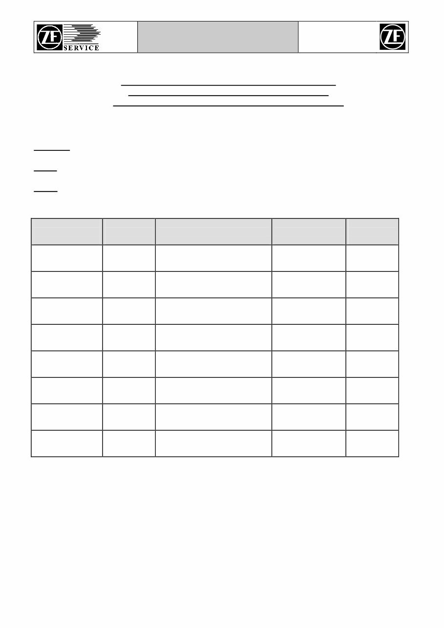
TIGHTENING TORQUES FOR SCREWS (IN Nm) ACC. TO ZF-STANDARD 148
Friction coefficient : μ tot.= 0.12 for screws and nuts without rework, as well as phophated
nuts. Tighten manually !
Take tightening torques from the chart below, unless otherwise specified:
Metric ISO-standard thread DIN 13, page 13
Size 8.8 10.9 12.9
M4 2.8 4.1 4.8
M5 5.5 8.1 9.5
M6 9.5 14 16.5
M7 15 23 28
M8 23 34 40
M10 46 68 79
M12 79 115 135
M14 125 185 215
M16 195 280 330
M18 280 390 460
M20 390 560 650
M22 530 750 880
M24 670 960 1100
M27 1000 1400 1650
M30 1350 1900 2250
M33 1850 2600 3000
M36 2350 3300 3900
M39 3000 4300 5100
Metric ISO-fine thread DIN 13, page 13
Size 8.8 10.9 12.9
M 8 x 1 24 36 43
M 9 x 1 36 53 62
M 10 x 1 52 76 89
M 10 x 1.25 49 72 84
M 12 x 1.25 87 125 150
M 12 x 1.5 83 120 145
M 14 x 1.5 135 200 235
M 16 x 1.5 205 300 360
M 18 x 1.5 310 440 520
M 18 x 2 290 420 490
M 20 x 1.5 430 620 720
M 22 x 1.5 580 820 960
M 24 x 1.5 760 1100 1250
M 24 x 2 730 1050 1200
M 27 x 1.5 1100 1600 1850
M 27 x 2 1050 1500 1800
M 30 x 1.5 1550 2200 2550
M 30 x 2 1500 2100 2500
M33 x 1.5 2050 2900 3400
M 33 x 2 2000 2800 3300
M 36 x 1.5 2700 3800 4450
M 36 x 3 2500 3500 4100
M 39 x 1.5 3450 4900 5700
M 39 x 3 3200 4600 5300
You're Reading a Preview
What's Included?
Fast Download Speeds
Online & Offline Access
Access PDF Contents & Bookmarks
Full Search Facility
Print one or all pages of your manual
$61.99
ZF Tractor Transmission ECCOM 1.5 Workshop Manual
Viewed 61 Times Today

What's Included?
Fast Download Speeds
Online & Offline Access
Access PDF Contents & Bookmarks
Full Search Facility
Print one or all pages of your manual
$61.99

Secure transaction
What's Included?
Fast Download Speeds
Online & Offline Access
Access PDF Contents & Bookmarks
Full Search Facility
Print one or all pages of your manual
Description
Explore our comprehensive tractor transmission manual for the ZF ECCOM 1.5 and SDFG Series 20. This manual is an invaluable resource for both professional mechanics and DIY enthusiasts. Whether you're looking to troubleshoot, repair, or maintain your tractor transmission, this manual provides detailed insights and step-by-step instructions to assist you in your endeavors.


