


IMPORTANT SAFETY NOTICE
Appropriate service methods and proper repair procedure are essential for the safe, reliable operation of all motor
vehicles as well as the personal safety of the individual doing the work. This Manual provides general directions for
accomplishing service and repair work with tested, effective techniques. Following them will help assure reliability.
There are numerous variations in procedures, techniques, tools and parts for servicing vehicles, as well as in the skill
of the individual doing the work. This Manual cannot possibly anticipate all such variations and provide advice or
cautions as to each. Accordingly, anyone who departs from the instructions provided in this Manual must first
establish that he compromises neither his personal safety nor the vehicle integrity by his choice of methods, tools or
parts.
NOTES, CAUTIONS, AND WARNINGS
As you read through the procedures, you will come across NOTES, CAUTIONS, and WARNINGS. Each
one is there for a specific purpose. NOTES give you added information that will help you to complete a
particular procedure. CAUTIONS are given to prevent you from making an error that could damage the
vehicle. WARNINGS remind you to be especially careful in those areas where carelessness can cause
personal injury. The following list contains some general WARNING that you should follow when you work
on a vehicle.
Always wear safety glasses for eye protection.
Use safety stands whenever a procedure requires you to be under the vehicle with the vehicle jacked up.
Be sure that the ignition switch is always in the OFF position, unless otherwise required by the procedure.
Set the parking brake when working on the vehicle. It should be in REVERSE (engine OFF) or NEUTRAL
(engine ON) unless instructed otherwise for a specific operation. Place wood blocks (4”X4” or larger) to the
front and rear surfaces of the tires to provide further restraint from inadvertent vehicle movement.
Operate the engine only in a well-ventilated area to avoid the danger of carbon monoxide.
Keep yourself and your clothing away from the moving parts, when the engine is running, especially the fan
and drive belts.
To prevent serious burns, avoid contact with hot metal parts such as the radiator, exhaust manifold tail pipe,
catalytic converter and muffler.
Do not smoke while working on the vehicle.
To avoid injury, always remove rings, watches, loose hanging jewelry, and loose clothing before beginning
to work on a vehicle. Tie long hair securely behind the head.
Keep hands and other objects clear of the radiator fan blades, Electric cooling fans can start to operate at any
time by an increase in under hood temperatures, even though the ignition is in the OFF position. Therefore,
care should be taken to ensure that the electric cooling fan is completely disconnected when working under
the hood.
Disconnect the negative battery ground cable before using any electric welding equipment.

Contents
Section Page
1 INTRODUCTION AND DESCRIPTION
1-1. Introduction ……………………………………………………………………….
1-10. Description………………………………………………………………………
1-1
1-1
2 T5 WC & STD ON-VEHICLE SERVICE AND TROUBLESHOOTING
2-1. Maintenance……………..………………………………………………………..
2-7. Troubleshooting…………………………………………………………………..
2-10. Transmission Removal… ………………………………………………………
2-21. Transmission Installation ………………………………………………………..
2-1
2-1
2-4
2-7
3 T5 WC DISASSEMBLY
3-1. General Information ……………………………………………………………...
3-6. T5 HD Transmission Disassembly Procedures ………………………………
3-1
3-1
4 T5 STD DISASSEMBLY
4-1. General Information ……………………………………………………………...
4-6. T5 STD Transmission Disassembly Procedures ……………………………..
4-1
4-1
5 T5 WC & STD CLEANING, INSPECTION, REPAIR OR REPLACEMENT
5-1. Cleaning …………………………………………………………………………..
5-5. Inspection …………………………………………………………………………
5-10. Repair or Replacement ………………………………………………………….
5-1
5-8
5-16
6 T5 WC ASSEMBLY
6-1. General Information ……………………………………………………………...
6-4. T5 HD Transmission Assembly Procedures …………………………………..
6-1
6-1
7 T5 STD ASSEMBLY
7-1 General Information ……………………………………………………………...
7-4. T5 STD Transmission Assembly Procedures ………………………………...
7-1
7-1

Section 1
Introduction and Description
1-1. INTRODUCTION
1-2. PURPOSE. This manual contains
maintenance, service and parts information for the
T5 Five-Speed Manual Transmission manufactured
by TREMEC (TRANSMISIONES Y EQUIPOS
MECANICOS S.A DE C.V.) Av. 5 de febrero No.
2115, Querétaro,Qro. México.
1-3. SCOPE. As you will see in the Table of
Contents, this manual provides information for
maintenance, troubleshooting, disassembly,
cleaning, inspection, repair or replacement, and
assembly of the transmission.
1-4. T5 TRANSMISSION CLASSES. Two
basic T5 transmission classes are covered in this
manual: WC (world class) and STD (standard).
Separate disassembly (Section 3 and 4) and
assembly (Sections 6 and 7) instructions are
provided for each of these classes. In other section
of the manual, variations within the classes are
noted in the instructions and illustrations.
NOTE
The parts shown in the illustrations in the service
instructions are typical for those used in a particular
class of transmission (WC or STD). Some parts may
be encountered in service that are different in
appearance than those illustrated. These “different”
parts perform the same function as those illustrated.
1-5. T5 TRANSMISSION CLASS
IDENTIFICATION. The T5 transmission can be
identified as WC or STD by the last three digits of
the transmission part number (see Table 3-1 or 4-1
in the disassembly sections). In this manual, figure
titles, lists, tables and main paragraph headings are
in the proper section for the transmission being
serviced.
1-6. PART IDENTIFICATION. Each detail part
shown in the exploded views in this manual for a
particular transmission class (WC or STD) is
assigned an index number. This same index
number is used to identify the part throughout this
manual. For example, WC index number 116 (in
parenthesis in the text) refers to the countershaft
gear in all applicable sections. The same is true for
STD index number 105.
1-7. The exploded view illustration in Section 5 (figure
5-1 or 5-2) make it possible to view the complete
transmission assembly in addition to the illustrations
in the Sections 3,4,6 and 7 relating to a specific
disassembly or assembly procedure.
1-8. PART NUMBERS. The purpose of the index
numbers in the illustrations in this manual is to identify
parts. Part numbers are not used. Once a part is
identified, refer to the TREMEC T5 Transmission
Parts Catalog for the correct part number.
1-9. ABBREVIATIONS. Abbreviations, other than
those in common use, found in this manual are
identified in Table 1-1.
1-10. DESCRIPTION
1-11. TRANSMISSION DESCRIPTION. The
TREMEC Automotive T5 is a five speed,
countershaft, helical gear transmission . It is fully
synchronized for ease of shifting. Gear ratios vary
from model to model (refer to vehicle service manual
for specifications.) The input and output ends of the
input and output shafts are supported by tapered
roller bearings. A pilot roller bearing is used between
the input and output shafts. The countershaft gear is
supported in tapered roller bearings for WC models
and straight roller beatings for STD models. These
and other basic differences in the two classes are
shown in Table 1-2.
1-12. APPLICATION. The T5 transmission is used on
sports cars, small to medium sedans and coupes,
compact trucks and vans, utility vehicles and similar
2-wheel and 4-wheel drive vehicles.
Table 1-1. Abbreviations
AR As Required
Assy Assembly
ID Inside Diameter
NP Not Procurable
OD Outside Diameter
PN Part Number
QTY Quantity
TIR Total Indicator Reading
Table 1-2. Basic Differences Between T5 WC and STD Classes
FEATURE DESCRIPTION
WC STD
Bearings under gears
Blocking rings
Countershaft bearings
Needle bearings
Fiber synchronizers
Tapered roller bearings
Journals
Brass synchronizers
Straight roller bearings
1-1

Section 2
T5 WC & STD On- Vehicle Service and Troubleshooting
2-1. MAINTENANCE
2-2 GENERAL. The only periodic maintenance
required for the TREMEC T5 transmission is to
maintain proper lubrication.
2-3. LUBRICATION SCHEDULE. Refer to the
Vehicle Owner’s Manual or Service Manual.
CAUTION
Excessive temperatures may bread down the
transmission lubricant (refer to vehicle service
manual for maximum allowable temperature). If there
is reason to believe that the transmission has been
subjected to temperatures exceeding 275° F, change
the lubricant immediately.
2-4. APPROVED LUBRICANT. Most T5
transmission models use Dexron II automatic
transmission fluid. Refer the vehicle owner’s manual
or service manual for lubricant specifications.
CAUTION
Do not mix different bands or types of transmission
lubricant. DO NOT USE GEAR OIL IN THE T5
TRANSMISSION SINCE THIS MAY DAMAGE THE
BLOCKING RING MATERIAL.
2-5. CHECKING LUBRICANT LEVEL. Proceed as
follows (see figure 2-2):
NOTE
To check or drain the lubricant, the transmission
should be warm. This is best done shortly after
engine shutdown.
a. Wipe fill plug (2) and surrounding area clean.
b. Remove fill plug (2).
c. When transmission is full, lubricant will just drip
out fill plug opening.
d. Add approved lubricant if required.
e. Install fill plug (2) and torque to 20 lb-ft (27 Nm).
2-6. CHANGING LUBRICANT. Proceed as follows
(see figure 2-2):
a. Wipe drain and fill plugs (1 and 2) and
surrounding areas clean.
b. Place suitable container under transmission.
c. Remove drain plug (1).
d. Remove fill plug (2).
e. Allow all lubricant to drain.
f. Install drain plug (1) and torque to 20 lb-ft
(27 Nm).
g. Add lubricant Through fill plug opening until
lubricant just begins to drip back out of opening.
NOTE
The amount of lubricant required varies from model
to model. Refer to the vehicle service manual for
transmission capacity.
h. Install fill plug and torque to 20 lb-ft (27 Nm).
2-7. TROUBLESHOOTING
2-8. GENERAL. In the event of operating difficulty,
it is recommended that the transmission (engine) be
shut down. In most cases, to accurately pinpoint the
source of trouble, it may be necessary to remove
and disassemble, or partially disassemble, the
transmission. Specific inspection procedures for
detail parts of the transmission are provided in
Section 5.
2-9. TROUBLESHOOTING CHART. Table 2-1 lists
troubles which may be encountered along with
possible causes and remedies.
2-1

Table 2-1. Troubleshooting Chart
PROBLEM POSSIBLE CAUSE REMEDY
Will not shift
(control lever
moves)
Control lever assy broken or damaged
Damaged offset lever, shift fork, selector
Plate or selector arm
Replace control lever and housing assy
Remove extension or adapter and case
Cover. Check for damaged parts. Replace
Damaged parts
Hard shift or
control lever will
not move into
gear
Clutch not releasing
Improper or low transmission lubricant
Shifter shaft or shift rail binding
Binding of sliding synchronizers or gears
If reverse only, seized backup switch
Worn or damaged flywheel pilot bushing
Bell housing misaligned
Adjust or replace clutch
Add or drain and replace with proper
Lubricant (refer to paragraph 2-4
Remove extension or adapter and case
Cover. Check for damaged parts. Replace
Damaged parts
Remove extension or adapter and case cover.
Reach down into transmission and
Check that synchronizers and gears (parts
With shifting grooves) slide freely on shafts.
Remove and replace damaged parts.
Remove and check backup switch.
Replace if seized
Replace pilot bushing
Align bell housing to within 0.010 inch
TIR on face and in bore.
Gears clash when
Shifting
Engine idle speed too high
Clutch damaged or out of adjustment
Pilot bearing between input shaft and
Output shaft binding
Damaged synchronizer
Bell housing misaligned
Damaged gear or gears
Worn or damaged flywheel pilot bushing
Adjust idle speed to specifications
Adjust or replace clutch
Disassemble and check bearing rollers,
Input shaft ID and output shaft OD.
Replace damaged parts
Disassemble and check for damaged
Synchronizer parts. Replace damaged parts
Align bell housing to within 0.010 inch
TIR on face and in bore
Disassemble and check for gear damage.
Replace damaged gears
Replace pilot bushing
Transmission
jumps out of gear
Loose transmission or flywheel housing
Bolts, improper alignment
Synchronizer damaged or excessively worn
Blocking ring damaged, worn index slots
Or friction surfaces worn or damaged
Excessive countershaft end play
Shifting fork loose on shaft or rail; worn
Or damaged fork or inserts
Torque bolts to specifications. Realign if
Necessary
Disassemble and check for worn or
Damaged synchronizer parts. Replace
Damaged parts
Disassemble and check blocking ring for
Damaged parts
Disassemble and check. Replace worn or
damaged parts. Reshim if roller bearings
Used.
Disassemble and check for wear or
Damage.
2-2

Table 2-1. Troubleshooting Chart (Cont)
PROBLEM POSSIBLE CAUSE REMEDY
Transmission
locked in one
gear
Fork or offset lever loose on shaft or rail
Worn or damaged forks, offset lever,
Shaft or rail
Worn or damaged synchronizer
Worn or damaged gears
Remove extension or adapter and case
Cover. Check for loose parts on shifter
shaft or rail. Replace roll pin(s). If still
loose, replace shaft or rail and/or
attached parts as required
Remove extension or adapter and case
Cover. Check for wear or damage,
Replace damaged parts
Disassemble and check for worn or
damaged synchronizer parts. Replace
worn or damaged parts
Disassemble and check for worn or
damaged gears. Replace worn or
damaged gears
Transmission
noise. NOTE:
Make sure noise
is coming from
transmission and
not clutch release
bearing or other
components.
Improper or low transmission lubricant
Loose bolts or other attaching parts
Improper flywheel housing to engine
crankshaft alignment
Noisy transmission bearings
Noisy gears
Add or drain and replace with proper
lubricant (refer to paragraph 2-4)
Make sure al attaching parts are torqued
to specifications
Check alignment and correct if necessary
per vehicle service manual
Disassemble and check bearing, bearing
rollers and parts in and on which
they operate for wear or damage.
Replace worn or damaged parts
Disassemble and check for worn or
damaged gears (including speedometer
gear). Replace worn or damaged gears
Transmission
leakage
Leakage from other components
Vent or breather clogged
Too much or improper lubricant
Loose bolts at sealing faces
Improperly applied sealant
Worn or damaged oil seal
Verify transmission leakage. Thoroughly
clean all exposed surfaces, then check
for leaks
Remove vent or breather and clean or
replace
Remove fill plug to check for excess, or
drain and replace
Torque bolts to specifications
Separate and thoroughly clean leaking
surfaces. Reapply sealant. Replace parts
and torque bolts to specifications
Replace oil seal
2-3
2-10. TRANSMISSION REMOVAL
2-11. GENERAL. The following paragraphs provide
procedures for removing the T5 transmission. For 4-wheel
drive vehicles, instructions are also given for removing the
transfer case. If the vehicle is not equipped with 4-wheel
drive, disregard paragraph 2-18 and references to the
transfer case in the other paragraphs
2-12. OTHER COMPONENTS. Before or during
transmission removal, it may be necessary to remove or
disconnect other components. This is required to provide
access to or clearance for the transmission ( and transfer
case, if used ). Since these components vary widely from
vehicle to vehicle, specific instruction are not provided in this
manual. Refer to the vehicle service manual. Such
components may include:
a. Console or similar cover.
b. Parking brake lever and controls.
c. Wiring and/or vacuum harness.
d. Exhaust system components.
e. Clutch components.
f. A skid plate or protective covers on the underside of the
vehicle.
1.13 SUPPORTING TRANSMISSION ( OR TRANSFER
CASE, IF USED) Before removing any parts which attach or
support the transmission(and transfer case, if used), support
the transmission on a suitable jack or stand. The jack or
stand must be capable of supporting and holding the
transmission independently. Also the jack or stand shall be
capable or lowering, raising and moving the transmission
laterally.
2-14. PROCEDURES WITH VEHICLE ON FLOOR. Before
raising the vehicle, proceed as follows:
a. Position vehicle over suitable hoist.
WARNING
When using a drive-on lift, be sure to properly chock the
wheels to prevent the vehicle from rolling off.
b. Disconnect negative battery terminal.
c. Shift vehicle into neutral and release parking brake. On
4-wheel drive vehicles, shift into 4HI.
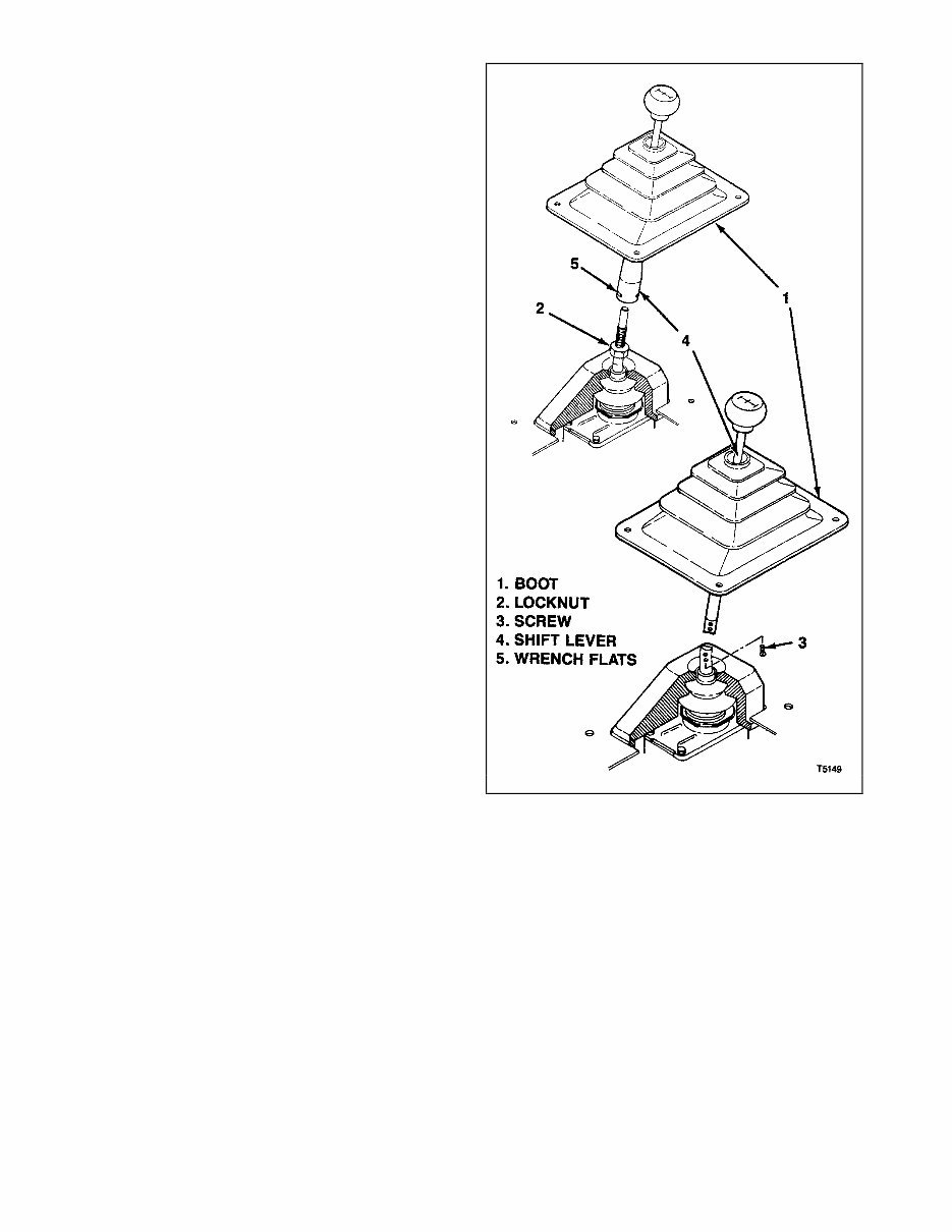
d. Remove shift lever (see figure 2-1):
1. Detach bottom of boot (1) so that it can be raised
to provide access to lower end of shift lever. Boot
attachment methods may vary from that shown.
2. If shift lever is threaded on, loosen lock nut (2),
then remove shift lever (4) using wrench on flats (5)
provided.
3. If shift lever is attached with screws (3), then
remove screws (3) and shift lever (4).
2-15. LIFTING VEHICLE. Lift vehicle on suitable hoist,
allowing clearance for removal of transmission (and transfer
case, if used), and related components such as propeller
shaft (or shafts), cross members and supports. If unsure,
refer to vehicle service manual for approved lift points.
NOTE
On some vehicles, it may be necessary to remove or
disconnect other components (refer to paragraph 2-12)
Figure 2-1. shift Lever
2-16. DRAINING LUBRICANT. Drain lubricant from
transmission (and transfer case, if used) (refer to
paragraph 2-6, steps a through e). Reinstall fill and drain
plugs.
2-17. REMOVING REAR PROPELLER SHAFT. The rear
propeller shaft (3, figure 2-2) is splined to the
transmission (or transfer case, if used) output shaft. It will
be necessary to disconnect the rear end of the propeller
shaft first, then move the shaft rearward to disengage the
splines. Support the propeller shaft to prevent it from
dropping. Bend universal joints just enough to permit
shaft removal. Otherwise damage may result. Refer to
the vehicle service manual for specific procedures.
2-4
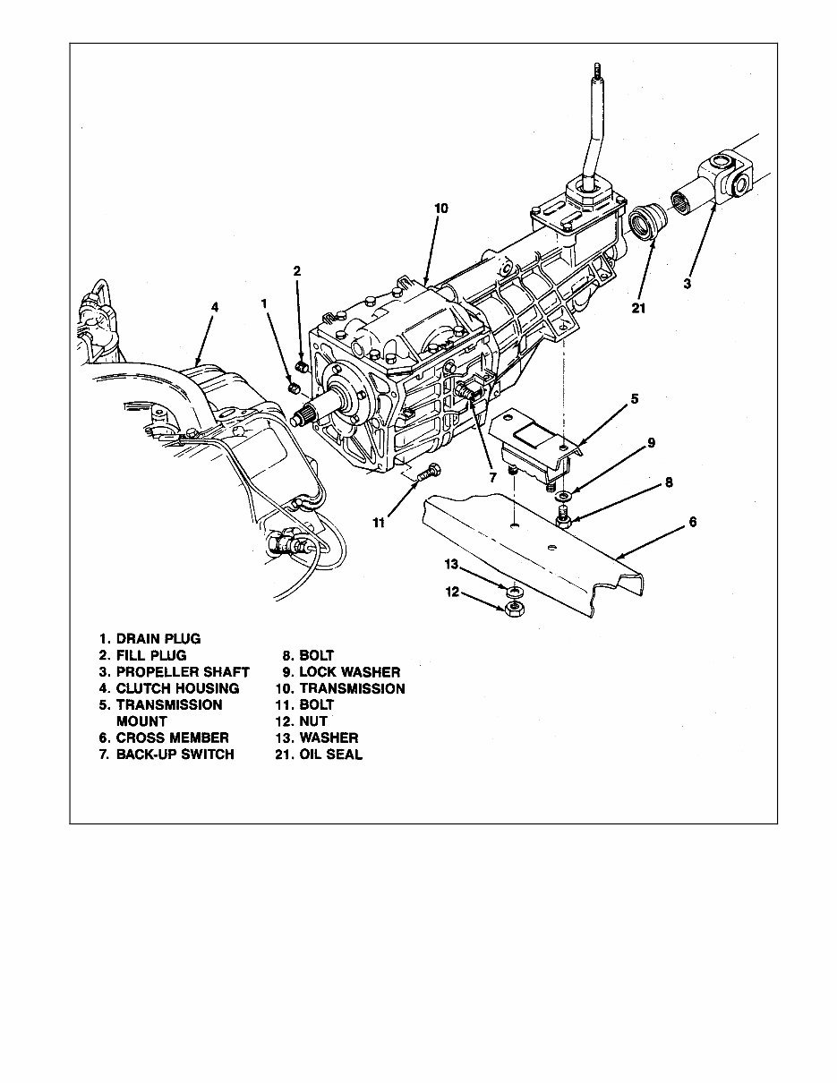
Figure 2-2. Transmission
2-5
2-18. REMOVING TRANSFER CASE (4-WHEEL
DRIVE VEHICLES ONLY). On 4-wheel vehicles,
proceed as follows to remove transfer case (see
figure 2-3 and 2-4 and refer to WARNING
following paragraph 2-14, step a):
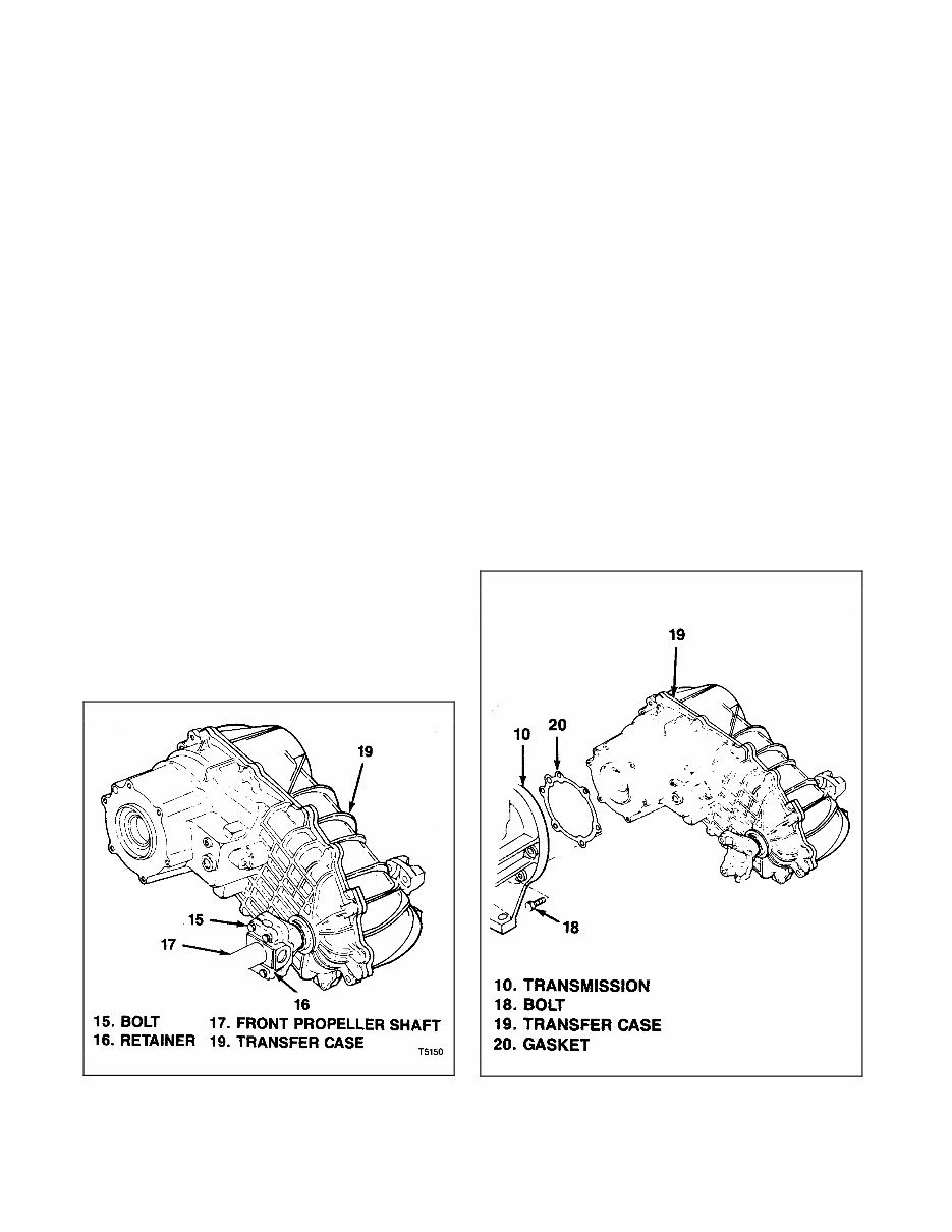
a. Remove front propeller shaft (17, figure 2-3) by
removing bolts (15) and retainers (16).
Observe same precautions in handling front
propeller shaft as for rear propeller shaft (refer
to paragraph 2-17).
b. Remove shift lever linkage and bracket
attached to transfer case and transmission.
c. Support transfer case on suitable jack or stand
(refer to paragraph 2-13).
CAUTION
Make sure transfer case is completely supported by
jack or stand before removing bolts (18,figure 2-4)
attaching transfer case to transmission. Do not
allow transfer case to “hang” from transmission by
splined shaft since this may damage input bearings.
d. Remove bolts (18) attaching transfer case (19)
to transmission (10).
e. Move transfer case (19) straight back toward
rear of vehicle to completely disengage splines
from transmission (10). Remove gasket (20).
f. Carefully lower transfer case on jack or stand.
2-19. REMOVING TRANSMISSION SUPPORT
BRACES. The main transmission attachment
points are at the clutch housing (4, figure 2-2) and
at the transmission mount (5) on the cross member
(6). Supplemental support braces may or may not
be used, depending on the vehicle. If used, remove
supplemental support braces and any other
components necessary to provide for transmission
clearance.
Figure 2-3. Front Propeller Shaft
2-20. REMOVING TRANSMISSION. Proceed as
follows (see figure 2-2 and refer to warning following
paragraph 2-14, step a):
a. Support transmission on suitable jack or stand
(refer to paragraph 2-13).
b. Remove back-up switch electrical connection
(7). Also, if used, remove neutral switch
electrical connector or any others that may be
used.
c. Remove speed sensor electrical harness or
speedometer cable (location may vary).
d. Remove bolts (8) and lockwashers (9) attaching
transmission (10) to transmission mount (5).
e. Remove cross member (6).
CAUTION
Make sure transmission is completely supported by
jack or stand before removing bolts (11) attaching
transmission (10) to clutch housing (4). Do not allow
transmission to “hang” from clutch by splined shaft
since this may damage input bearings.
f. Remove bolts (11) attaching transmission (10) to
clutch housing (4).
g. Using care not to dislodge clutch parts, move
transmission (10) straight back toward rear of
vehicle to completely disengage splines from
clutch.
h. Carefully lower transmission (10) on jack or
stand.
Figure 2-4. Transfer Case
2-6

2-21. TRANSMISSION INSTALLATION
2-22. GENERAL. Install Transmission (and transfer
case, if used) in vehicle from which it was removed as
described in the following paragraphs. Note the
following:
CAUTION
T5 transmissions are not necessarily
interchangeable from vehicle to vehicle. Installation
of the transmission in a vehicle other than that from
which it was removed may result in premature
failure.
a. The following paragraphs provide procedures for
installing the T5 transmission. For 4-wheel drive
vehicles, instructions are also given for installing the
transfer case. If the vehicle is not equipped with 4-
wheel drive, disregard paragraph 2-24 and
references to the transfer case in the other
paragraphs.
b. Before or during removal of the transmission, parts
not specifically related to the transmission may
have been removed to provide access or clearance.
Be sure to reinstall these components exactly as
they were prior to removal (refer to paragraph 2-12).
c. The transmission (and transfer case, if used) must
be supported on a suitable jack or stand capable of
raising it the transmission into position, aligning
and moving it to engage the drive splines.
2-23. INSTALLING TRANSMISSION. Proceed as
follows (see figure 2-2):
a. Apply thin coat of high temperature grease to input
shaft spline on transmission (10).
b. Shift transmission (10) into high gear and raise on
jack or stand. Align transmission with clutch
housing(4).
CAUTION
Make sure transmission is in exact alignment with
clutch before engaging splines. Do not force
transmission input shaft into clutch. Otherwise
damage may result. If necessary, turn transmission
output shaft to align input shaft spline with that in
clutch.
c. Carefully move transmission (10) forward, engaging
splines in clutch, until transmission mounting flange
contacts clutch housing (4).
CAUTION
Keep transmission completely supported by jack or
stand until bolts (11) attaching transmission (10) to
clutch housing (4) are installed and torqued. Do not
allow transmission to “hang” from clutch by splined
shaft since this may damage input bearings.
d. Make sure mounting holes in transmission (10) and
clutch housing (4) are aligned and install bolts (11).
Torque bolts to 55 lb-ft (75 Nm). Do not remove jack
or stand at this time.
e. Install cross member (6). Install bolts (8) and
lockwashers (9) attaching transmission (10) to
transmission mount (5). Torque bolts to 35lb-ft (59
Nm).
d. Remove jack or stand supporting transmission .
e. Install speed sensor electrical harness or
speedometer cable (location may vary).
f. Install back-up switch electrical connection (7)
and any other electrical connectors that were
removed.
g. Install any supplemental supports or braces that
were removed during transmission removal.
WARNING
Be sure to fill transmission with proper fluid (refer
to paragraph 2-4). Otherwise transmission will be
damaged when engine is started. If vehicle is
driven, transmission could lock up causing
personal injury.
2-24. INSTALLING TRANSFER CASE (4-WHEEL
DRIVE VEHICLES ONLY). On 4-wheel drive vehicles,
proceed as follows to install transfer case (see figure
2-3 and 2-4):
a. Apply thin coat of high temperature grease to
output shaft spline on transmission (10, figure 2-
4).
b. Install new gasket (20) on transfer case (19)
mounting face.
c. Raise transfer case (19) on jack or stand. Align
transfer case with transmission (10).
CAUTION
Make sure transfer case is in exact alignment with
transmission before engaging splines. Do not
force transfer case onto transmission. Otherwise
damage may result. If necessary, turn transfer case
output shaft to align input shaft spline with that on
transmission.
d. Carefully move transfer case (19) forward,
engaging splines on transmission, until transfer
case mounting flange contacts transmission (10).
CAUTION
Keep transfer case completely supported by jack
or stand until bolts (18) attaching transfer case
(19) to transmission (10) are installed and torqued.
Do not allow transmission to “hang” from clutch
by splines shaft since this may damage input
bearings.
e. Make sure mounting holes in transmission (10)
and transfer case (19) are aligned and install bolts
(18). Torque bolts to 23 lb-ft (31 Nm). Remove
jack or stand.
f. Attach shift lever bracket and linkage removed at
transfer case removal.
g. Make sure front propeller shaft (17, figure 2-3) is
properly lubricated and install. Attach to transfer
case (19) with retainer (16) and bolts (15). Torque
bolts to 15 lb-ft (29Nm).
WARNING
Be sure to fill transfer case with proper fluid (refer
to vehicle service manual). Otherwise transfer
case will be damaged when engine is started. If
vehicle is driven, transfer case could lock up
causing personal injury.
2-7
You're Reading a Preview
What's Included?
 Lifetime Access
Fast Download Speeds
Online & Offline Access
Access PDF Contents & Bookmarks
Full Search Facility
Print one or all pages of your manual
$55.99
Tremec T5 WC STD transmission gearbox workshop service repair manual
Viewed 15 Times Today

What's Included?
Lifetime Access
Fast Download Speeds
Online & Offline Access
Access PDF Contents & Bookmarks
Full Search Facility
Print one or all pages of your manual
$55.99

Secure transaction
What's Included?
Lifetime Access
Fast Download Speeds
Online & Offline Access
Access PDF Contents & Bookmarks
Full Search Facility
Print one or all pages of your manual
Description
The Tremec T5 WC (T5WC) and STD transmission system is utilized in various passenger vehicles and light trucks, including:
- Ford Mustang
- TVR Cerbera and Tuscan
- Chevy Blazer and S-10 Pick up
- Ssangyong Musso and Korando


