


ABBREVIATIONS USED IN THIS MANUAL
A/T ATM Automatic Transmission
ATF Automatic Transmission Fluid
B
0
Overdrive Brake
B
1
Second Coast Brake
B
2
Second Brake
B
3
First and Reverse Brake
C
0
Overdrive Clutch
C
1
Forward Clutch
C
2
Direct Clutch
D Disc
D/F Differential
LH Left
MP Multipurpose
O/D Overdrive
P Plate
RH Right
SSM Special Service Materials
SST Special Service Tools
IN-6
- INTRODUCTION Abbreviations Used in This Manual
WWW.ALL-TRANS.BY
ProCarManuals.com
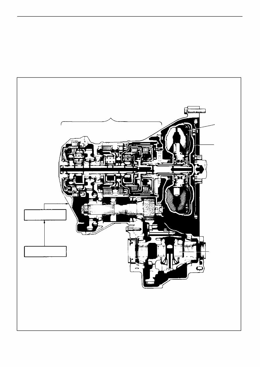
AT3754
Electronic Control
System
Differential
Hydraulic Control
System
Torque
Converter
Lock-up
Clutch
4-speed Planetary
Gear Unit
Sectional View
DESCRIPTION
GENERAL
(A540E)
The A540E is a 4-speed, Electronic Controlled Transaxle (hereafter called ECT) developed exclusively
for use with a transversely-mounted engine. A lock-up is built into the torque converter.
The A540E transaxle is mainly composed of the torque converter, the 4-speed planetary gear unit, the
differential, the hydraulic control system and the electronic control system.
AT-2
- AUTOMATIC TRANSAXLE Description
WWW.ALL-TRANS.BY
ProCarManuals.com
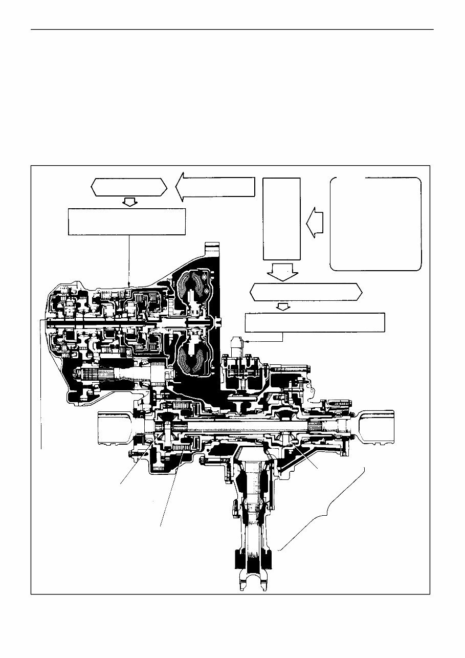
AT5032
(A540H)
The A540H automatic transaxle design is based on the A540E automatic transaxle and equipped with a
center differential and transfer.
This transaxle has the same hydraulic multiplate clutch in the center differential limiting control mecha-
nism as the A241H automatic transaxle on the Corolla All-Trac/4WD Station Wagon. The fluid pressure
acting on the hydraulic multiplate clutch of the A540H is controlled by the ECT ECU (Electronic Control
Unit) according to the vehicle driving conditions. As a result, torque is distributed to the front and rear
wheels appropriately at all times to maximize the overall performance of the 4WD vehicle.
NOTICE: Special handling methods are necessary for full-time 4WD vehicles during inspection and
maintenance. Instructions concerning these handling methods are given on Camry Repair Manual
(Pub. No. RM199U) on page IN-8.
Hydraulic Multiplate Clutch
Transfer
Front Differential
Center
Differential
4-Speed Planetary Gear
Unit and Hydraulic
Control System
No. 1 and No. 2 Center Differential
Control Solenoid Valve
Center Differential Control
ECT
ECU
No. 1 and No. 2 Shift Control
Solenoid Valves and Lock-up
Control solenoid Valve
S Engine ECU
S Throttle Position
Sensor
S Stop Light Switch
S Vehicle Speed
Sensors
S Mode Select Switch
S Neutral Start Switch
S O/D Main Switch
S Center Deff. Control
Switch
Shift Control
Sectional View
Sensors
- AUTOMATIC TRANSAXLE Description
AT-3
WWW.ALL-TRANS.BY
ProCarManuals.com
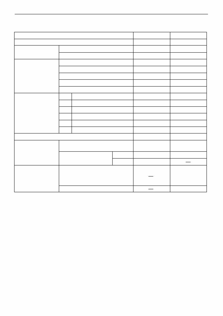
Type of Transmission
A540E A540H
Type of Engine 2VZ-FE 3S-FE
Torque Converter
Stall Torque Ratio
1.9 : 1 2.0 : 1
Lock-Up Mechanism Equipped
←
Gear Ratio
1st Gear 2.810
←
2nd Gear 1.549
←
3rd Gear 1.000
←
O/D Gear 0.734
←
Reverse Gear 2.296
Number of Discs and
Plates (Disc/Plate)
C
0
O/D Direct Clutch 2/2
←
C
1
Forward Clutch 4/4
←
C
2
Direct Clutch 3/3
←
B
2
2nd Brake 3/3
←
B
3
First & Reverse Brake 7/7 6/6
B
0
O/D Brake 3/3
←
mm (in.) B
1
Band Width 38 (1.50) 25 (0.98)
ATF
Type ATF DEXRONL II
ATF Type T or
equivalent
Capacity liter
(US qts, Imp. qts)
A/T 5.9 (6.2, 5.2) 7.0 (7.4, 6.2)
D/F 1.0 (1.1, 0.9)
Transfer Oil
Type
Transaxle oil E50,
API GL5,
SAE 75W-90
or equivalent
Capacity liter (US qts, Imp. qts) 0.7 (0.7, 0.6)
General Specification
←
AT-4
- AUTOMATIC TRANSAXLE Description
WWW.ALL-TRANS.BY
ProCarManuals.com
AT3206
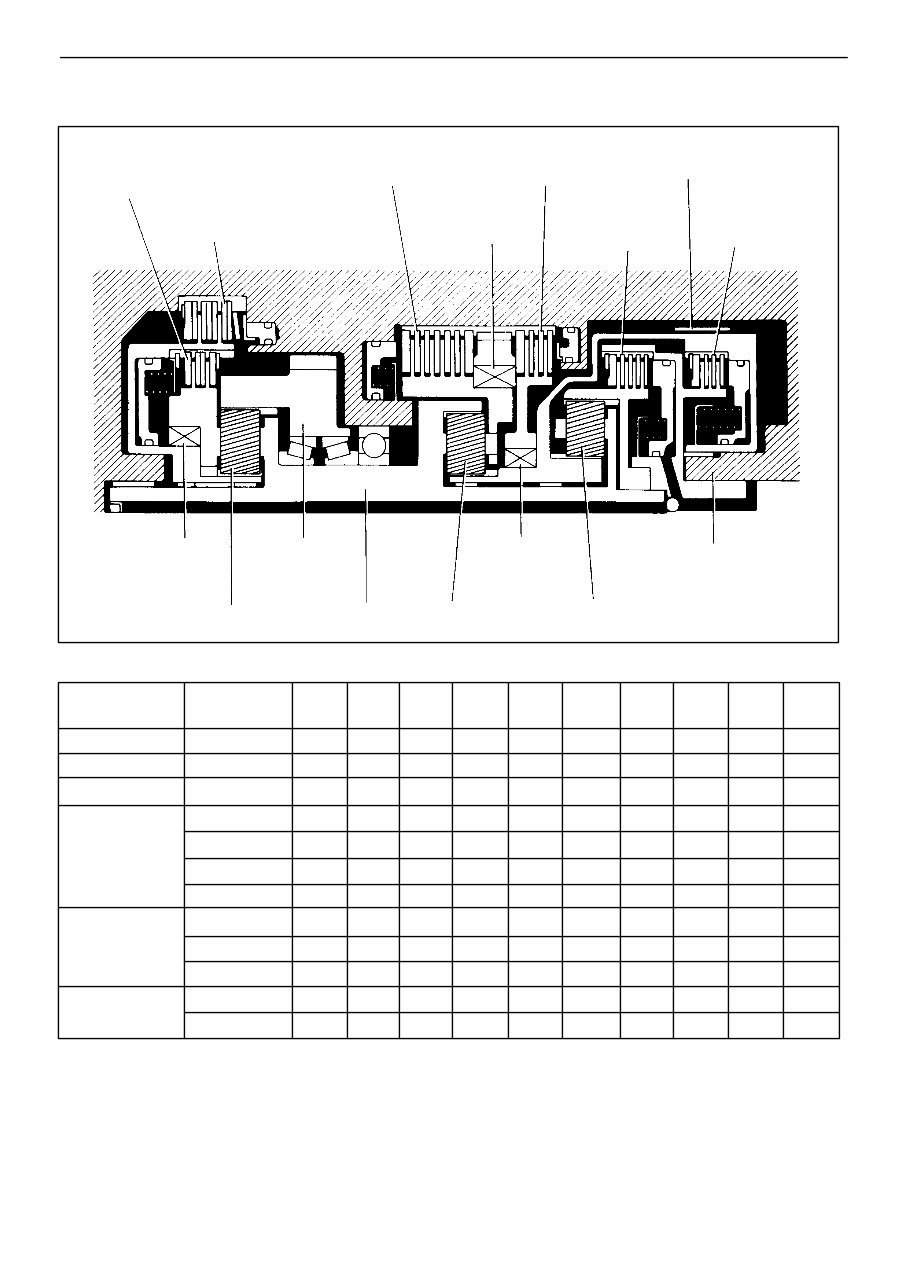
Planetary Gear Unit
Shift lever
position
Gear position C
0
C
1
C
2
B
0
B
1
B
2
B
3
F
0
F
1
F
2
P
Parking
L
R
Reverse
L L L
N Neutral
L
D
1st L L L L
2nd
L L L L L
3rd
L L L L L
O/D
L L L L
2
1st
L L
L L
2nd
L L L L L L
*3rd L L L L L
L
1st
L L
L L L
*2nd
L L L L L L
OPERATION
A540E, A540H
L..... Operating
*Down-shift only-no up-shift
Rear Planetary
Gear
Front Planetary
Gear
Intermediate
Shaft
O/D Planetary
Gear
O/D One-Way
Clutch (F
0
)
One-W ay Clutch
No. 1 (F
1
)
Counter
Drive Gear
Input Shaft
Forward
Clutch (C
1
)
Direct
Clutch (C
2
)
One-W ay Clutch
No. 2 (F
2
)
O/D Brake (B
0
)
O/D Direct
Clutch (C
0
)
First and Reverse
Brake (B
3
)
Second Brake (B
2
)
Second Coast
Brake (B
1
)
- AUTOMATIC TRANSAXLE Operation
AT-5
WWW.ALL-TRANS.BY
ProCarManuals.com
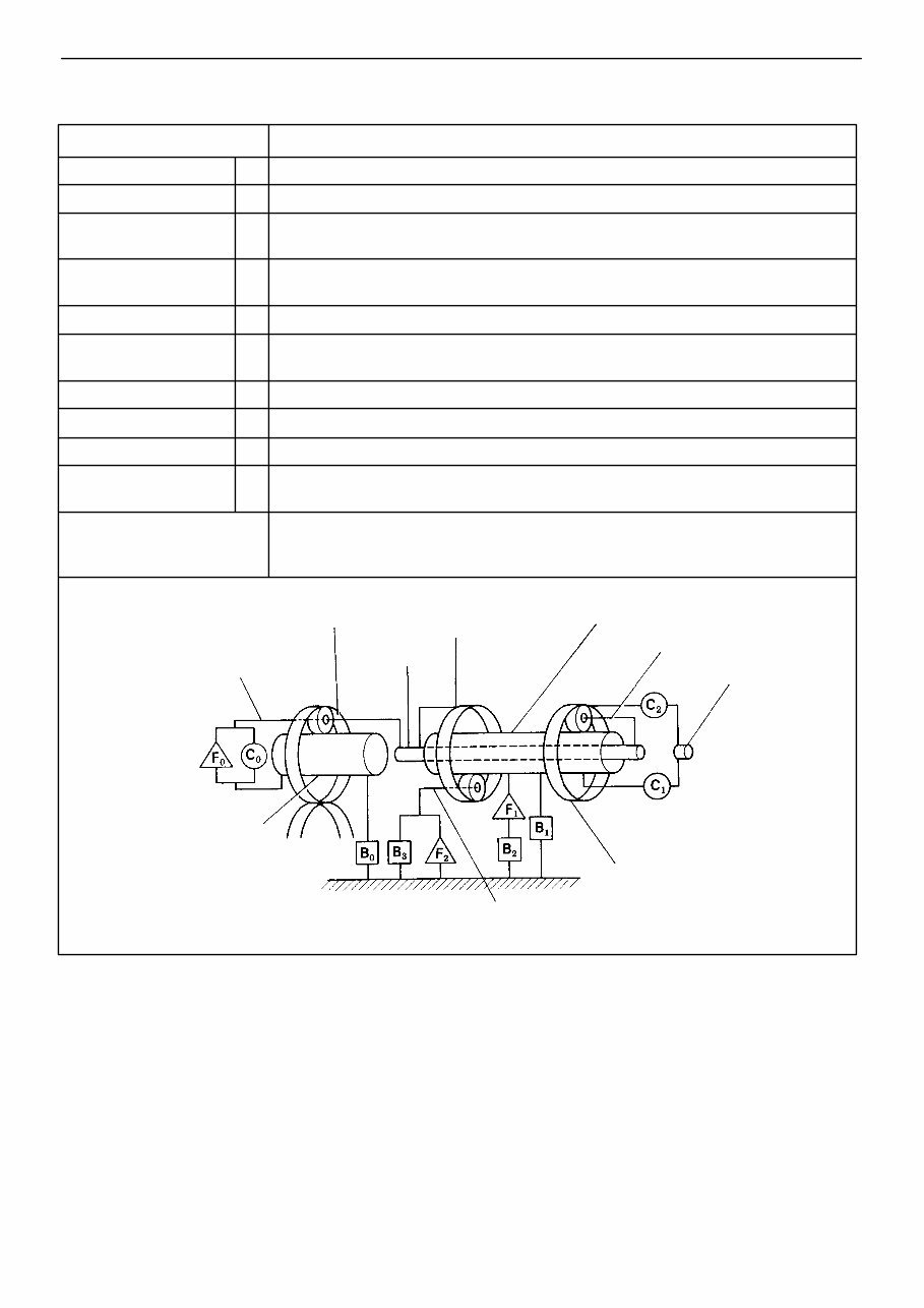
NOMENCLATURE OPERATION
Forward Clutch C
1
Connects input shaft and front planetary ring gear
Direct Clutch C
2
Connects input shaft and front & rear planetary sun gear
2nd Coast Brake B
1
Prevents front & rear planetary sun gear from turning either clockwise or counterclockwise
2nd Brake B
2
Prevents outer race of F
1
from turning either clockwise or counterclockwise, thus preventing front &
rear planetary sun gear from turning counterclockwise
1st & Reverse Brake B
3
Prevents rear planetary carrier from turning either clockwise or counterclockwise
No. 1 One-Way Clutch F
1
When B
2
is operating, prevents front & rear planetary sun gear from turning counterclockwise
No. 2 One-Way Clutch F
2
Prevents rear planetary carrier from turning counterclockwise
O/D Direct Clutch C
0
Connects overdrive sun gear and overdrive-planetary carrier
O/D Brake B
0
Prevents overdrive sun gear from turning either clockwise or counterclockwise
O/D One-Way Clutch B
0
When transmission is being driven by engine, connects overdrive sun gear and overdrive carrier
Planetary Gears
These gears change the route through which driving force is transmitted in accordance with the
operation of each clutch and brake in order to increase or reduce the input and output speed
AT3207
Rear Planetary Carrier
Front Planetary Ring Gear
OUT
O/D Planetary Sun Gear
IN
Input Shaft
Shaft
O/D Planetary Carrier
Intermediate
Front Planetary Carrier
Rear Planetary
Ring Gear
O/D Planetary Ring Gear
and Counter Drive Gear
FUNCTION OF COMPONENTS
Front and Rear Planetary Sun Gear
AT-6
- AUTOMATIC TRANSAXLE Operation
WWW.ALL-TRANS.BY
ProCarManuals.com
AT1097
OUT
IN
D or 2 Range 1st Gear
AT1102
OUT
IN
2 Range 2nd Gear
AT1098
OUT
IN
D Range 2nd Gear
AT1103
OUT
IN
L Range 1st Gear
AT1099
OUT
IN
D Range 3rd Gear
AT1101
OUT
IN
R Range Reverse Gear
AT1100
OUT
IN
D Range O/D Gear
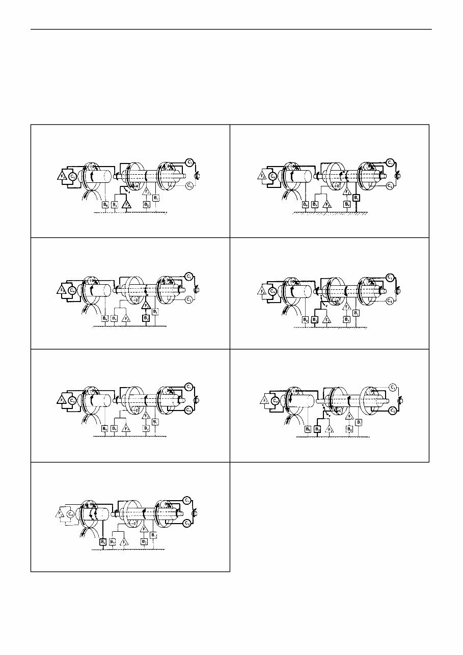
Power from the engine transmitted to the input shaft via the torque converter is then transmitted to the
planetary gears by the operation of the clutch.
By operation of the brake and one-way clutch, either the planetary carrier or the planetary sun gear are
immobilized, altering the speed of revolution of the planetary gear unit.
Shift change is carried out by altering the combination of clutch and brake operation.
Each clutch and brake operates by hydraulic pressure; gear position is decided according to the throttle
opening angle and vehicle speed, and shift change automatically occurs.
The conditions of operation for each gear position are shown on the following illustrations:
- AUTOMATIC TRANSAXLE Operation
AT-7
WWW.ALL-TRANS.BY
ProCarManuals.com
VALVE BODY
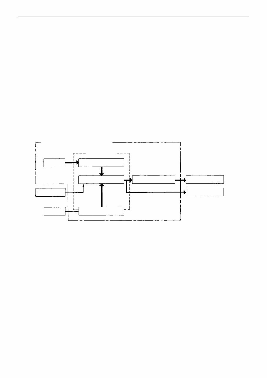
Hydraulic Control System
R A540E, A540H
The hydraulic control system is composed of the oil pump, the valve body, the solenoid valves, the accu-
mulators, the clutches and brakes, and the governor valve as well as the fluid passages which connect all
of these components.
Based on the hydraulic pressure created by the oil pump, the hydraulic control system governs the hy-
draulic pressure acting on the torque converter, clutches and brakes in accordance with the vehicle driving
conditions.
There are three solenoid valves on the valve body.
The No. 1 and No. 2 solenoid valves are turned on and off by signals from ECU to operate the shift valves
and change the gear shift position.
The No. 3 solenoid valve is operated by signals from the ECU to engage or disengage the lock-up clutch
of the torque converter.
R A540H
There are two center differential control solenoid valves on the transfer.
The solenoid valves are adjusting the center differential control pressure.
HYDRAULIC CONTROL SYSTEM
Hydr. pressure control OIL PUMP
CLUTCHES & BRAKES Fluid passage switching Planetary gear unit
Torque converter Throttle Cable
SOLENOID VALVES ECU
AT-8
- AUTOMATIC TRANSAXLE Operation
WWW.ALL-TRANS.BY
ProCarManuals.com
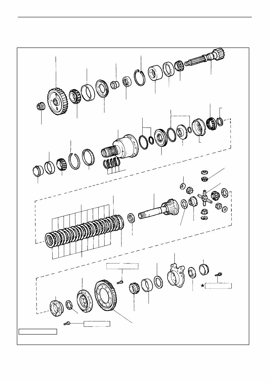
AT4670
♦ Non-reusable part
RPrecoated part
: Specified torque kg-cm (ft-lb, N-m)
340 (25, 33)
Ring Gear
No. 2 Thrust Washer
Left Case Bearing
Left Case Bearing Outer Race
Oil Baffle
195 (14, 19)
Ring Gear Mounting Left Case
1,260 (91,124)
Plate
Adjusting
Shim
♦ Oil Seal
No. 1 Thrust Washer
Side Gear
Disc
Flange
Front Differential
Right Case
♦ Right Case
Bearing
Differential
Spider
Speedometer
Drive Gear
♦ Oil Seal
Ring
Differential Pinion
No. 2 Piston
Piston Reaction
Sleeve
Right Case Bearing
Outer Race
Snap Ring
♦ Lock Nut
♦ Bearing
♦ O-Ring
Snap Ring
♦ O-Ring
Drive Pinion
No. 2 Spacer
Piston Return
Spring
Bearing Cage
Outer Race
Bearing
Drive Pinion
Outer Race
♦ Spacer
Counter Driven Gear
Snap Ring
Ring Gear Mounting
Right Case
Oil Slinger
No. 1 Piston
Pinion Thrust Washer
Ring Gear
Mounting
Case Sleeve
Side Gear
Thrust Washer
LH Bearing Retainer Snap Ring
Front Differential
Left Case
Differential Assembly (A540H)
COMPONENTS
AT-106
- AUTOMATIC TRANSAXLE Component Parts (Differential Assembly-A540E, A540H)
WWW.ALL-TRANS.BY
ProCarManuals.com
AT4300
AT4302
Sleeve
AT4301
Oil Seal Ring
AT4303
AT4299
Outer Race
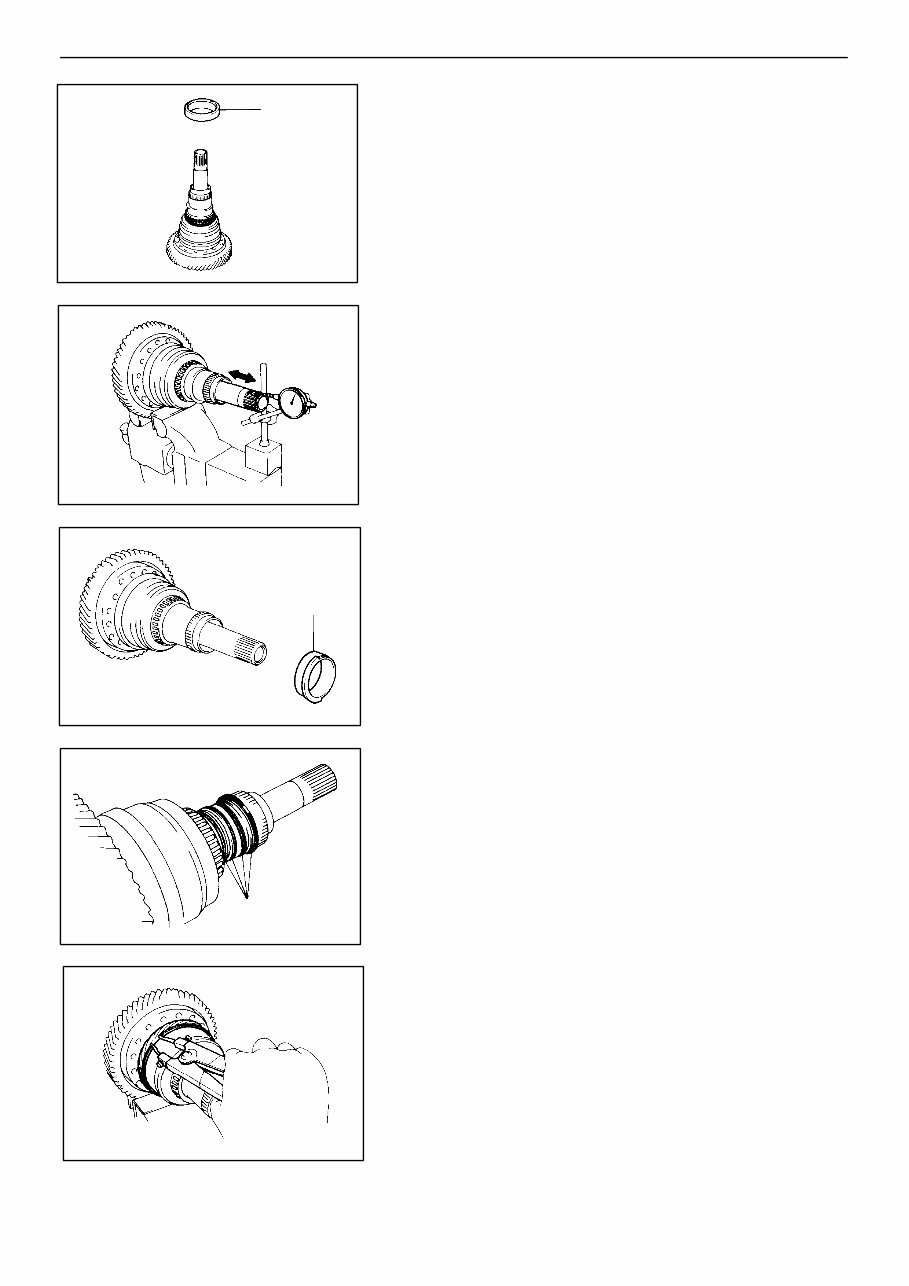
DISASSEMBLY OF DIFFERENTIAL ASSEMBLY
1. REMOVE RIGHT SIDE BEARING OUTER RACE
2. CHECK DIFFERENTIAL END PLAY
Using a dial indicator, measure the differential end play.
End play: 0.18 - 0.82 mm (0.0071 - 0.0323 in.)
3. REMOVE RING GEAR MOUNTING CASE SLEEVE
4. REMOVE OIL SEAL RINGS
Remove four oil seal rings from the ring gear mounting
right case.
5. REMOVE SPEEDOMETER DRIVE GEAR
Using snap ring pliers, remove the snap ring and the
speedometer drive gear.
- AUTOMATIC TRANSAXLE Component Parts (Differential Assembly-A540E, A540H)
AT-107
WWW.ALL-TRANS.BY
ProCarManuals.com
You're Reading a Preview
What's Included?
 Lifetime Access
Fast Download Speeds
Online & Offline Access
Access PDF Contents & Bookmarks
Full Search Facility
Print one or all pages of your manual
$27.99
Automatic Transmission A540E Service Manual
Viewed 75 Times Today

What's Included?
Lifetime Access
Fast Download Speeds
Online & Offline Access
Access PDF Contents & Bookmarks
Full Search Facility
Print one or all pages of your manual
$27.99

Secure transaction
What's Included?
Lifetime Access
Fast Download Speeds
Online & Offline Access
Access PDF Contents & Bookmarks
Full Search Facility
Print one or all pages of your manual
Description
The manual you will receive contains all the necessary instructions for repairing your transmission. It is used by professional mechanics and DIY enthusiasts alike. This manual provides technical information, illustrations, diagrams, technical specifications, and step-by-step explanations for servicing your car's transmission. It is designed to be easily understood with basic mechanical knowledge, enabling you to save money on repairs and ensure your transmission runs at its best.


