

Spicer
®
Single Drive Axles
Service Manual
Single Reduction & Single Reduction with Differential Lock
AXSM-0060
May 2016
17060S
17060D
19060S
19060D
21060S
21060D
22060S
22060D
P19060S
P21060S
P22060S
Important Notice
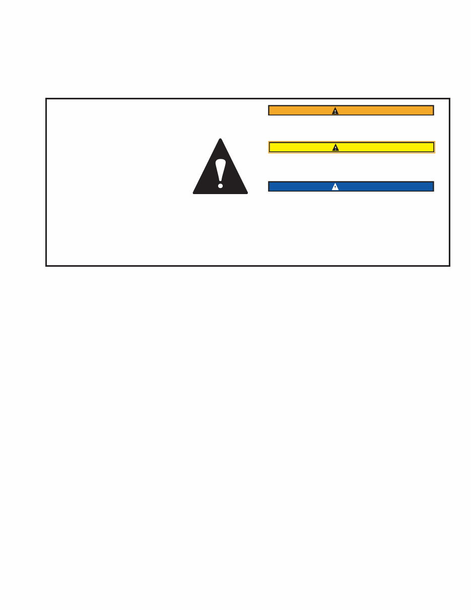
This symbol is used throughout this
manual to call attention to procedures
where carelessness or failure to follow
specific instructions may result in
personal injury and/or component
damage.
Departure from the instructions, choice
of tools, materials and recommended
parts mentioned in this publication may
jeopardize the personal safety of the
service technician or vehicle operator.
WARNING
WARNING: Failure to follow indicated procedures creates
a high risk of personal injury to the servicing technician.
CAUTION
CAUTION: Failure to follow indicated procedures may
cause component damage or malfunction.
IMPORTANT
IMPORTANT: Highly recommended procedures for proper
service of this unit.
NOTE: Additional service information not covered in the
service procedures.
Tip: Helpful removal and installation procedures to aid
in the service of this unit.
Always use genuine Spicer replacement parts.

AXSM-0060 May 2016 II
Table of Contents
Table of Contents
General Information
Introduction .................................................................. 1
Model Listing ................................................................ 1
Model Identification ...................................................... 2
Parts Identification ....................................................... 2
Ring Gear and Pinion .................................................... 3
Inspection
Failure Analysis ........................................................... 4
Inspect Assembly ........................................................ 6
Inspect Axle Housing .................................................. 6
Inspect Primary Gearing ..............................................6
DIfferential Carrier
Exploded View ............................................................. 7
Remove Differential Carrier ......................................... 8
Install Differential Carrier ........................................... 9
Carrier Assembly - Exploded View ............................ 10
Disassemble Carrier Assembly ................................... 10
Remove Wheel Differential - With Differential Lock .. 10
Remove Wheel Differential .......................................... 12
Remove Pinion Assembly ............................................ 13
Pinion Assembly
Exploded View ........................................................... 14
Disassembly & Overhaul Drive Pinion ......................... 15
Replace Pinion Bearing Cage Cups ............................ 16
Adjust Pinion Bearing Preload (Trial Buildup) ............. 17
Adjust Pinion Bearing Preload (Final Buildup) ............ 18
Install Drive Pinion Assembly ..................................... 21
Wheel Differential
Exploded View ........................................................... 22
Disassemble, Overhaul, & Assemble ......................... 23
Measure and Adjust Carrier Assembly ....................... 26
Adjust Ring and Pinion Tooth Contact Pattern ........... 28
Wheel Differential Lock
Exploded View ........................................................... 30
Install and Adjust Wheel Differential Lock ................ 31
Install and Adjust Ring Gear Thrust Bolt ................... 32
Replace Seal ............................................................. 33
Housing Breather
Install New Housing Breather (Metal and Plastic) .... 34
Wheel End Seal
Exploded View ........................................................... 35
Remove and Overhaul Wheel End Seal ..................... 36
Install Wheel End Seal .............................................. 36
Wheel Adjustment Systems
Adjust Wheel Bearing ................................................ 37
Wheel End
Verify Wheel End-Play Procedure .............................. 39
Adjust End-Play with Tire & Wheel Assembly ............ 39
Adjust End-play with Wheel Hub ................................ 39
Lubricate Wheel End.................................................... 40
Lubrication
Approved Lubricants ................................................... 41
Recommendations for Viscosity / Ambient Temp ........ 41
Lube Change Intervals ................................................. 42
Change Lube ................................................................ 43
Towing
Proper Vehicle Towing ................................................. 44
Theory of Operation
Wheel Differential Assembly Operation ....................... 45
Wheel Differential Lock Operation ............................... 46
Parts Identification
Rear Drive Axle Parts - Exploded View ......................... 48
Axle Housing - Exploded View ...................................... 49
Torque Chart
Fastener Torque Specifications...................................... 50

1 AXSM-0060 May 2016
General Information
General Information
The description and specifications contained in this service
publication are current at the time of printing.
Dana reserves the right to discontinue or to modify its models
and/or procedures and to change specifications at anytime
without notice.
Any reference to brand names in this publication is made
simply as an example of the types of tools and materials
recommended for
use and should not be considered an endorsement.
Equivalents, if available, may be used.
Introduction
Dana presents this publication to aid in maintenance and
overhaul of Spicer single reduction drive axles. Instructions
contained cover the models listed below. Their design
is common, with differences in load capacity. Capacity
variations are achieved by combining basic differential
carrier assemblies with different axle housings, axle shafts
and wheel equipment. The suffix letter “P” in the model
number indicates a lube pump is standard. Pump models are
equipped with a gerotor pump, designed to provide additional
lubrication to the inter-axle differential and related parts.
Model Listing
The following models are included in this publication.
Rear Axle Load Capacity
17060S 17,600
19060S
P19060S
19,000
21060S
P21060S
21,000
22060S
P22060S
22,000
19 06 0 S
GAWR x 1000 lbs.
Series (family)
Gearing:
D - Single Reduction with
Wheel Differential Lock
I - Integral Brake
L - Limited-Slip
N - No-Spin
O - Rolled Over
P - Lube Pump
R - Retarder/Parking Brake Ready
S - Single Reduction
T - Duel Reduction
W - Wide-track
Design level
AXSM-0060 May 2016 2
General Information
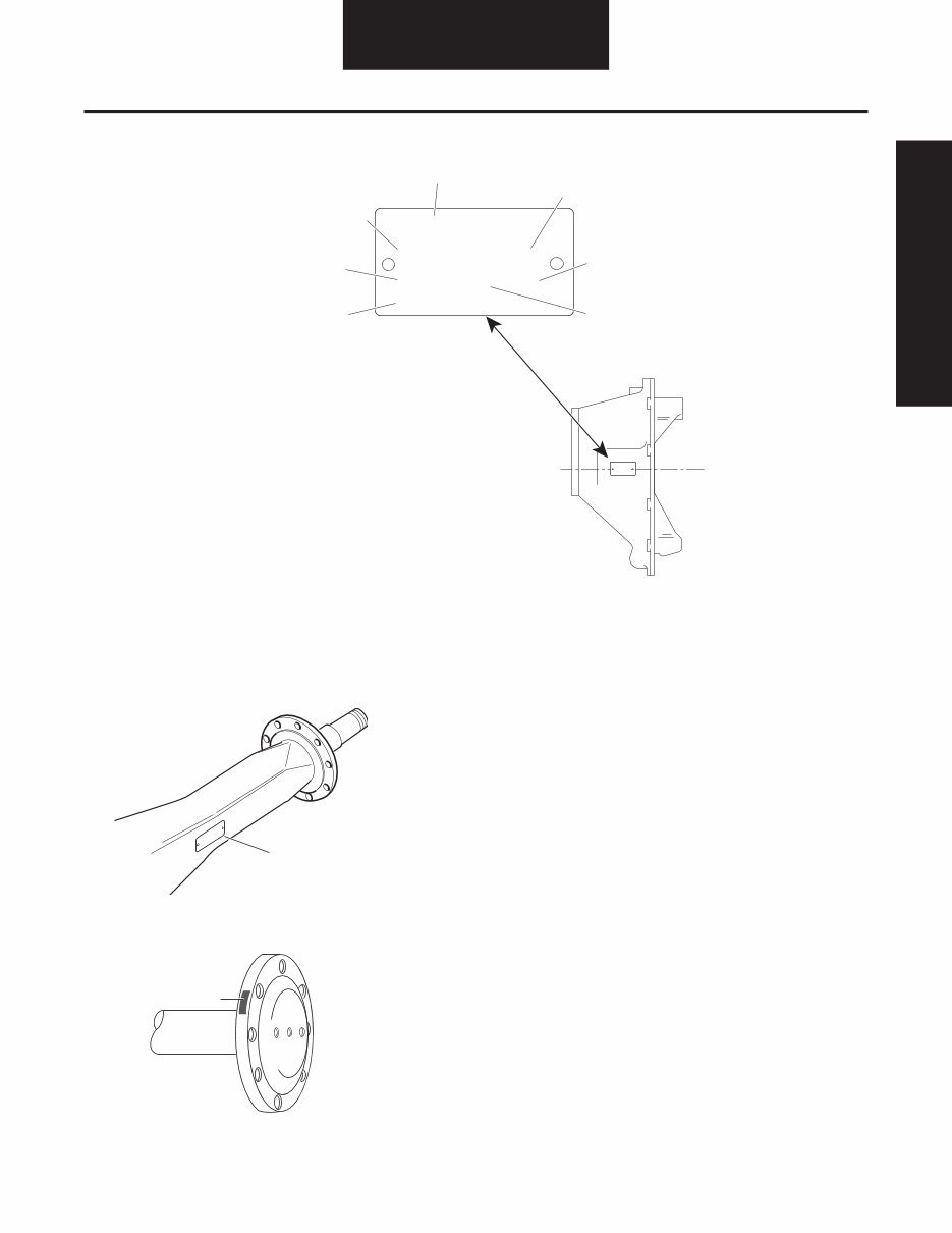
Model Identification
Parts Identification
Axle Housing
Axle Shaft
Data plate is located on
the axle centerline
Rear Axle (Top View)
4
6
5
1
3
2
7
Spicer
®
MODEL PART NO. RATIO
MADE IN:
SPEC. SERIAL NO.
CUST. PART NO.
Spicer
1 - Country of origin
2 - Axle modle identification
3 - Specification number assigned to the axle
built by Spicer. Identifies all component parts
of the axle including special OEM requirements
such as yoke or flanges.
4 - OEM part number assigned to the axle build
5 - Carrier assembly serial number assigned by
the manufacturing plant
6 - Axle gear ratio
7 - Carrier assembly production or service part number
Axle Shaft
Part Number
PT. NO .
HSG. CAP. LBS.
HSG. I.D. NO.
HO USING MADE IN
Spicer
®
Identification
Tag
General Information
3 AXSM-0060 May 2016
General Information
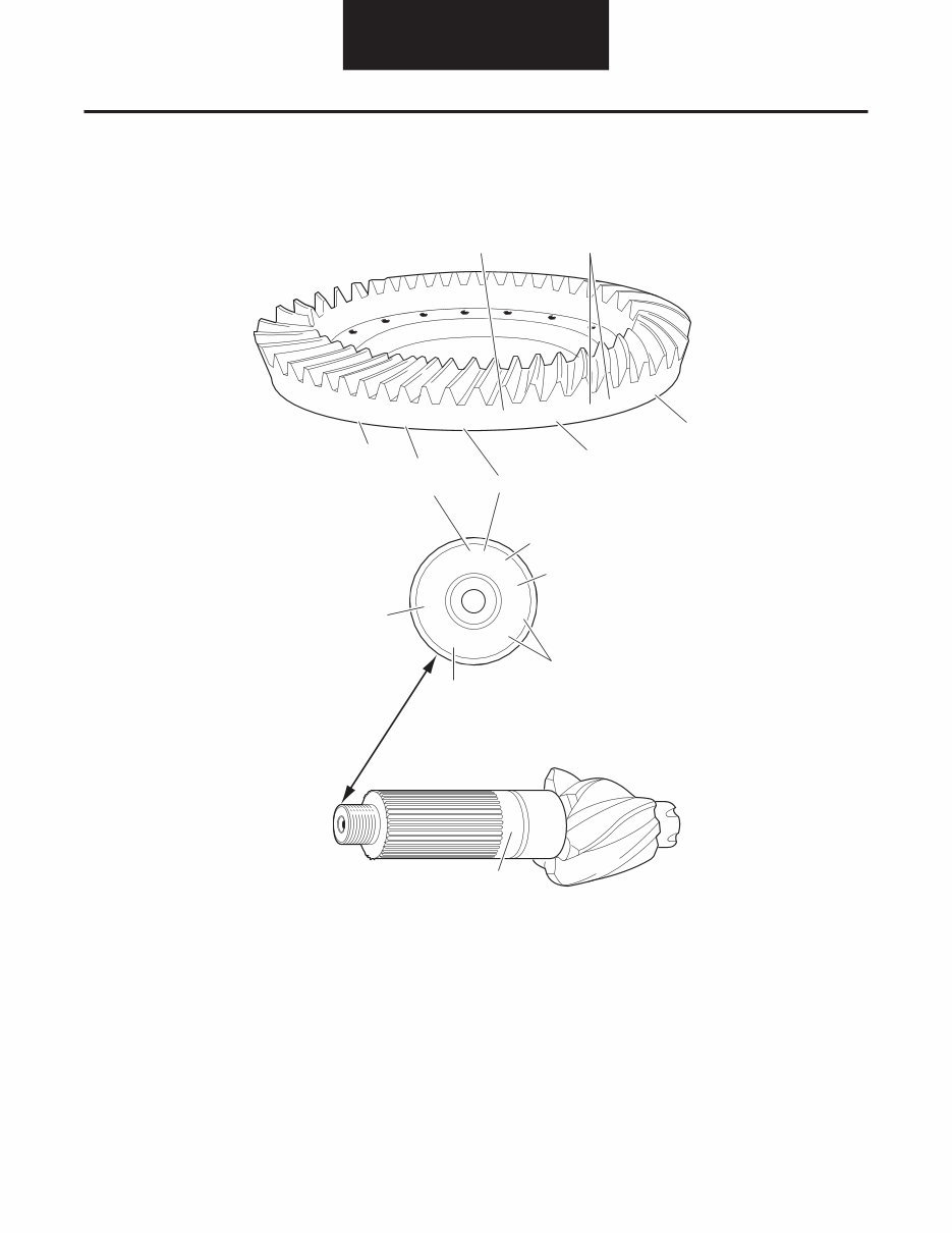
Ring Gear and Pinion
NOTE: Ring gear and drive pinion are matched parts and must be replaced in sets.
1 - Part number
2 - Number of ring gear teeth
3 - Manufacturing numbers
4 - Matching gear set number
5 - Number of pinion teeth
6 - Date code
7 - Indicates genuine Spicer parts
8 - Heat code
41-8
SPICER
127381
OF
NL2
17
127
8-41
127428
SPICER
17
G
6-39
JD77
85405
DANA
86
5
2
3
1
7
8
L
7
0
3
8
1
4
L7038
4
7
G
3
127
0H
6
8
6

AXSM-0060 May 2016 4
Inspection
Failure Analysis
Failure analysis is the process of determining the original cause
of a component failure in order to keep it from happening
again. Too often, when a failed component is replaced without
determining its cause, there will be a recurring failure. If a carrier
housing is opened, revealing a ring gear with a broken tooth, it
is not enough to settle on the broken tooth as the cause of the
carrier failure. Other parts of the carrier must be examined. For
a thorough understanding of the failure and possible insight into
related problems, the technician needs to observe the overall
condition of the vehicle.
No one benefits when a failed component goes on the junk
pile with the cause unknown. Nothing is more disturbing to
a customer than a repeat failure. Systematically analyzing a
failure to prevent a repeat occurrence assures quality service
by avoiding unnecessary downtime and further expense to the
customer.
The true cause of a failure can be better determined by knowing
what to look for, determining how a piece of the equipment was
running and learning about previous problems. In the case of a
rebuilt rear axle, mismatched gears may have been installed.
The more successful shops prevent repeat equipment failures
by developing good failure analysis practices. Knowing how
to diagnose the cause of a premature failure is one of the
prerequisites of a good heavy-equipment technician.
How to Diagnose a Failure
The following five steps are an effective approach to good failure
diagnostics.
1. Document the problem.
2. Make a preliminary investigation.
3. Prepare the parts for inspection.
4. Find the cause of the failure
5. Correct the cause of the problem.
Document the Problem
Here are some guidelines for starting to learn about a failure,
including questions to ask:
• Talk to the operator of the truck.
• Look at the service records.
• Find out when the truck was last serviced.
• Ask: In what type of service is the truck being used?
• Ask: Has this particular failure occurred before?
• Ask: How was the truck working prior to the failure?
You need to be a good listener. Sometimes, insignificant or
unrelated symptoms can point to the cause of the failure.
• Ask: Was the vehicle operating at normal temperatures?
• Ask: Were the gauges showing normal ranges of operation?
• Ask: Was there any unusual noise or vibration?
After listening, review the previous repair and maintenance
records. If there is more than one driver, talk to all of them and
compare their observations for consistency with the service and
maintenance records. Verify the chassis Vehicle Identification
Number (VIN) number from the vehicle identification plate, as
well as the mileage and hours on the vehicle.
Make a Preliminary Investigation
These steps consist of external inspections and observations
that will be valuable when combined with the results of the parts
examination.
• Look for leaks, cracks or other damage that can point to the
cause of the failure.
• Make note of obvious leaks around plugs and seals. A missing
fill or drain plug would be an obvious cause for concern.
• Look for cracks in the carrier housing (harder to see, but
sometimes visible).
• Does the general mechanical condition of the vehicle indicate
proper maintenance or are there signs of neglect?
• Are the tires in good condition and do the sizes match?
• If equipped with a torque-limiting device, is it working
properly?
During the preliminary investigation, write down anything out of
the ordinary for later reference. Items that appear insignificant
now may take on more importance when the subassemblies are
torn down.
Inspection

5 AXSM-0060 May 2016
Inspection
Prepare the Parts for Inspection
After the preliminary investigation, locate the failure and prepare
the part for examination. In carrier failure analysis, it may be
necessary to disassemble the unit.
• When disassembling subassemblies and parts, do not clean
the parts immediately since cleaning may destroy some of the
evidence.
• When tearing down the drive axle, do it in the recommended
manner. Minimize any further damage to the unit.
• Ask more questions when examining the interior of the
carrier. Does the lubricant meet the manufacturer specifications
regarding quality, quantity and viscosity? As soon as you have
located the failed part, take time to analyze the data.
Find the Cause of the Failure
Here begins the real challenge to determine the exact cause of
the failure. Keep in mind that there is no benefit to replacing
a failed part without determining the cause of the failure. For
example, after examining a failed part and finding that the failure
is caused by a lack of lubrication, you must determine if there
was an external leak. Obviously, if there is an external leak, just
replacing the failed gear is not going to correct the situation.
Another important consideration here is to determine the specific
type of failure which can be a valuable indicator for the cause
of failure. The following pages show different types of failures
and possible causes. Use this as a guide in determining types of
failures and in correcting problems.
Correct the Cause of the Problem
Once the cause of the problem has been determined, refer to the
appropriate service manual to perform the repairs.
AXSM-0060 May 2016 6
Inspection
Inspect Assembly
Clean
1. Wash steel parts with ground or polished surfaces in solvent.
There are many suitable commercial solvents available. Kerosene
and diesel fuel are acceptable.
WARNING
Gasoline is not an acceptable solvent because of its
extreme combustibility. It is unsafe in the workshop
environment.
2. Wash castings or other rough parts in solvent or clean in hot
solution tanks using mild alkali solutions.
NOTE: If a hot solution tank is used, make sure parts are heated
thoroughly before rinsing.
3. Rinse thoroughly to remove all traces of the cleaning solution.
4. Dry parts immediately with clean rags.
5. Oil parts.
• If parts are to be reused immediately: Lightly oil.
• If parts are to be stored: Coat with oil, wrap in corrosion
resistant paper and store in a clean, dry place.
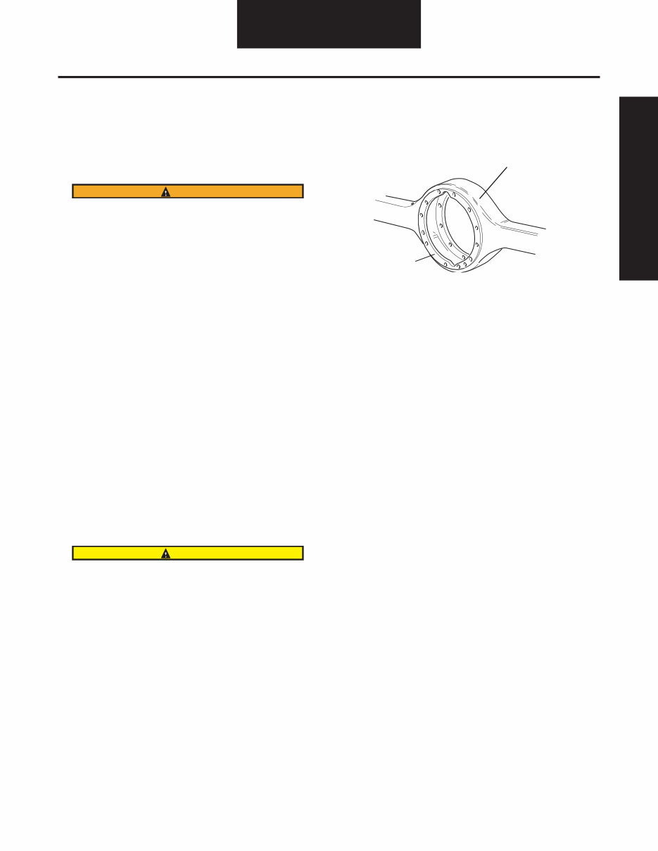
Inspect Axle Housing
Axle housing inspection and repairs are limited to the following
checks or repairs:
• Visually inspect axle housing for cracks, nicks and burrs on
machined surfaces.
• Check carrier bolt holes and studs for foreign material.
• Replace damaged fasteners. Look for loose studs or cross
threaded holes.
CAUTION
Any damage which affects the alignment or structural
integrity of the housing requires housing replacement.
Do not repair by bending or straightening. This process
can affect the material’s properties and cause it to fail
completely under load.
• Check all seals and gaskets.
NOTE: Replace conventional gaskets with silicone rubber gasket
compound (included in many repair kits). The compound provides
a more effective seal against lube seepage and is easier to
remove from mating surfaces when replacing parts.
1 - Axle housing
2 - Machined surface
Inspect all steel parts for:
• Notches, visible steps or grooves created by wear.
• Pitting or cracking along gear contact lines.
• Scuffing, deformation or discolorations. These are signs
of excessive heat in the axle and are usually related to low
lubrication levels or improper lubrication practices.
In addition, inspect the following for damage:
• Differential gearing.
• Bearings for loose fit on drive pinion, pilot bearing, and
differential bearings.
• All fasteners for rounded heads, bends, cracks or damaged
threads.
• Inspect machined surfaces of cast or malleable parts. They
must be free of nicks, burrs, cracks, scoring, and wear.
• Look for elongation of drilled holes, wear on surfaces machined
for bearing fits and nicks or burrs in mating surfaces.
Inspect Primary Gearing
Before reusing a primary gear set, inspect teeth for signs of
excessive wear. Check tooth contact pattern for evidence of
incorrect adjustment.
1
2
Inspection
7 AXSM-0060 May 2016
Differential Carrier
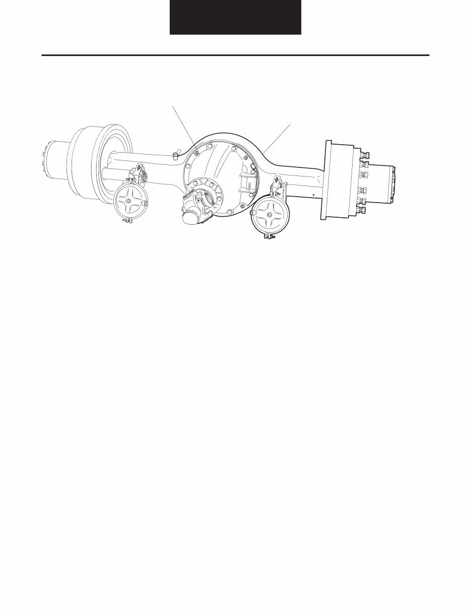
Differential Carrier Assembly - Exploded View
3
2
1
1 - Carrier Fasteners
2 - Carrier Assembly
3 - Single Axle Assembly
You're Reading a Preview
What's Included?
 Lifetime Access
Fast Download Speeds
Online & Offline Access
Access PDF Contents & Bookmarks
Full Search Facility
Print one or all pages of your manual
$46.99
DANA Spicer Single Drive Axles Service Manual
Viewed 74 Times Today

What's Included?
Lifetime Access
Fast Download Speeds
Online & Offline Access
Access PDF Contents & Bookmarks
Full Search Facility
Print one or all pages of your manual
$46.99

Secure transaction
What's Included?
Lifetime Access
Fast Download Speeds
Online & Offline Access
Access PDF Contents & Bookmarks
Full Search Facility
Print one or all pages of your manual
Description
These digital manuals provide comprehensive information on various model variations, including the description and operation of the controlled traction differential (CTD). They are invaluable resources for both professional mechanics and DIY enthusiasts.
- Checking the effectiveness of the controlled traction differential
- Clutch pack lubrication
- Driver-controlled CTD shift unit
- CTD adjustments
- Shifting seasonal CAD
- Fastener tightening specifications
The manuals cover all types of differential carrier assemblies, including medium-duty and heavy-duty CTDs. They provide detailed instructions on removing, disassembling, assembling, and installing clutch packs for all types of assemblies.
- Remove differential carrier assembly from axle housing
- Remove differential and clutch pack assembly from carrier
- Remove and disassemble clutch pack
- Assemble and install clutch pack
- Install differential and clutch pack assembly in carrier
- Adjust differential bearing preload
- Install differential carrier assembly in axle housing
- Functional CTD check (after repair or overhaul)
Additionally, the manuals provide specific guidance on driver-controlled type CTD shift systems for both single and tandem axles, along with troubleshooting information for each type.
- Driver-controlled type CTD shift system (single axles)
- Troubleshooting (single axles)
- CTD shift system (tandem axles)
- Troubleshooting (tandem axles)
- Selector valves
- Air shift unit


