R OLLS IR{ ROYCE Automatic Gearbox Workshop Manual Rolls-Royce Silver Dawn Rolls-Royce Silver Cloud I, II and III Rolls-Royce Phantom V and VI Bentley'R' type Bentley S1, S2 and S3 Bentley Continental TSD Publication 2042
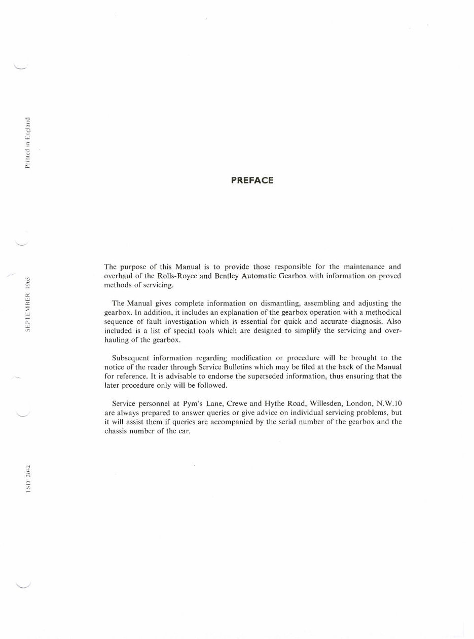
'2 ':l' ;:: PREFACE The purpose of this Manual is to provide those responsi bl e for the maintenance a nd overha ul of th e Ro ll s-Royce and Bentley Automatic Gearb ox with information on proved methods of servicing. The Manual give s co mplete info rm ation on dismantling, assembling a nd adjust in g the gearbox. In ad di tion, it includes an explanation of the gearbox operation with a methodical seq uence of fa ult in vestigation wh ic h is essential for qui ck and acc ur ate diagnosis. Also included is a li st of special too ls which are designed to simplify the servicing and over- ha uli ng of th e gearbox. S ubse qu e nt info rmation regardin b modifi cati on or procedure will be brought to the not ic e of the reader through Service Bulletins wh ic h may be fil ed at th e back of the Manual for refe ren ce. It is advisable to endorse the superseded informa ti on, thus en suring that the later procedure o nl y will be fo ll owed. Service personnel at Pym's Lane, Crewe and Hythe R oad, Willesden, Londo n, N.W. lO arc always prepared to an swer que ri es or give advice on individual servicing pro bl ems, but it will assist them if qu e rie s are accompanied by the serial number of the gea rbox and the chassis number of th e car.
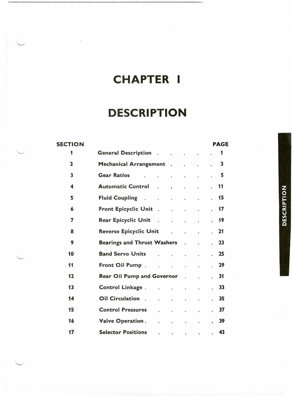
CHAPTER I DESCRIPTION SECTION PAGE 1 Gene ral Description 1 2 Mechanical Arrangement 3 3 Gear Ratios 5 4 Automatic Control 11 5 Fluid Coupling 15 6 Front Epicyclic Unit 17 7 Rear Epicyclic Unit 19 8 Reverse Epicyclic Unit 21 9 Bearings and Thrust Washers 23 10 Band Servo Units 25 11 Front Oil Pump . 29 12 Rear Oil Pump and Governor 31 13 Control Linkage . 33 14 Oil Circulation 35 15 Control Pressures 37 16 Valve Operation. 39 17 Selector Positions 43
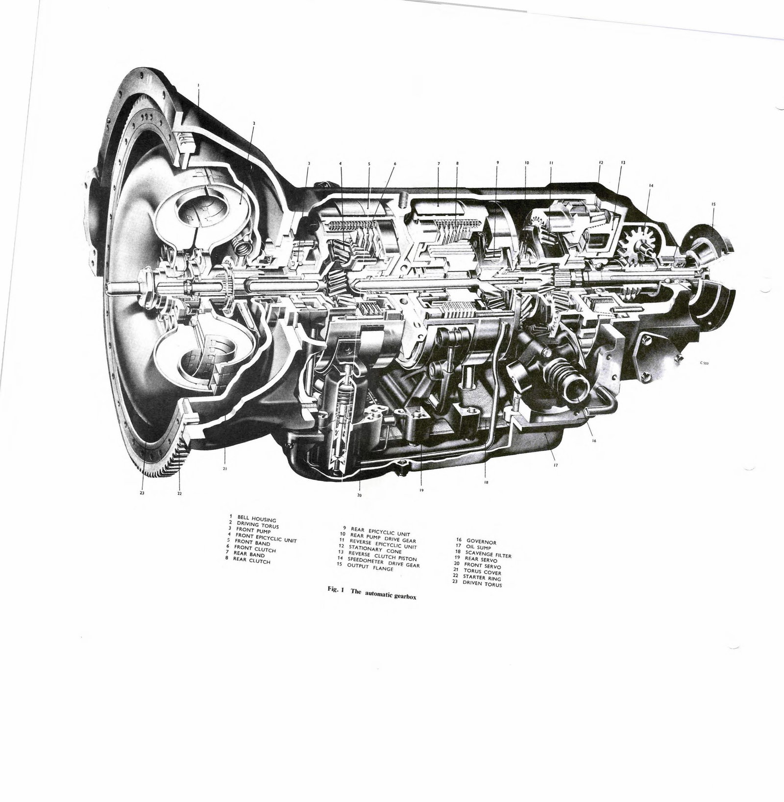
I - , I ) • , • , • , " " " /) " .. " " " II " 1 SELL HOUSING , REAR EPICYCLIC UNIT 16 GOVERNOR , DRIVING TORUS 10 REA.R. PUMP DRIYE GEAR, 17 Oil SUMP J FRONT PUMP 1! REVERSE EPICYCLIC UNIT 18 SCAVENG E FIl TEA • FRONT EPICYCLIC UNIT " STATIONARY CONE 19 REAR SERVO 5 fRONT BAND IJ REVERSE CLUTCH PISTON '0 FRONT SERVO • FRONT C LUTCH " SPEEDO METER DRIVE GEAR " TORUS COVER 7 REAR BAND 15 OUTPUT FLANGE " STARTER. RI NG 8 REAR CLUTCH " DRIVEN TORUS Fig. J 'The automatic gearhox
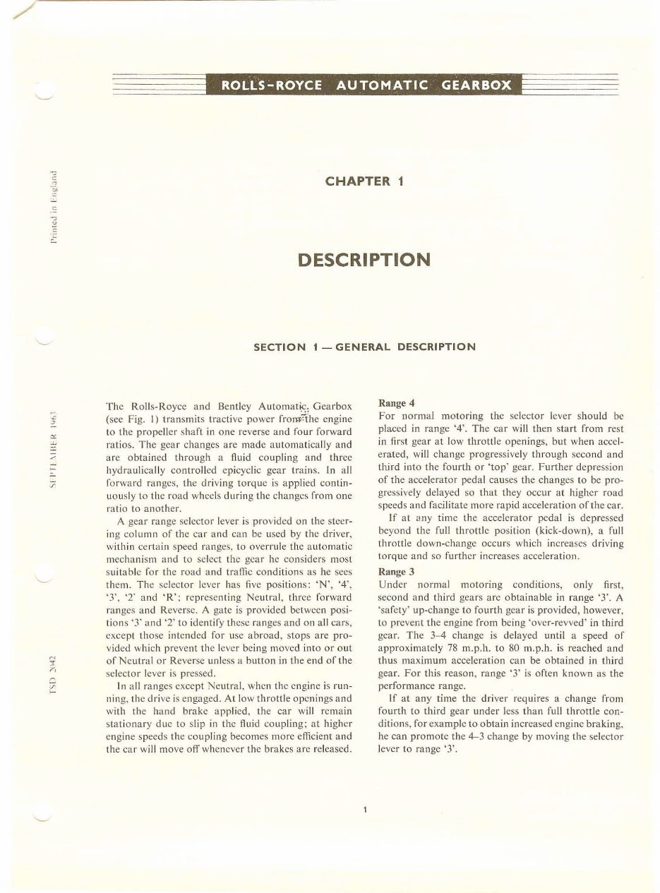
/' c " :r. ROLLS-ROYC CHAPTER 1 DESCRIPTION SECTION 1 - GENERAL DESCRIPTION T he Rolls-Royce and Be ntley Automatic: Gea rbox (sec Fig. I) transmits tractive power frorn::ihe engine to the propeller shaft in one reverse and four forward ratios. The gear changes are mad e a utomat ica ll y and arc ob ta ined through a fluid coup ling and three hydraul ica ll y con tro ll ed ep icyclic gear train s. In a ll fo rward ranges, the driving to rqu e is a pp lied con tin- uously to the r oad wheels during the changes from one ratio to anot he r. A gear range sel ector lever is pro vided on the steer- in g co lumn of the car and can be used by the driv er . within certain speed ranges, to overrule the automatic mechanism and to select the gear he co ns id ers most suitab le fo r the road and t raffic conditions as he sees them. The selector lever has fi ve positions: 'N', '4', '3'. '2' and • R': rep resenting Neutral, three forward ranges and Reverse. A gate is provided between posi~ li ons '3' and '2' to identify these ranges an d 011 a ll cars , except those in tended for use ab road. stop s a re pro~ vidcd which prevent the lever being moved into or out of Neu tral or Reverse unless a button in the end of the s el ect or lever is pressed. In a ll ranges except Neutral, whc n the engine is run~ ning, thc driv e is engaged. At low throttle openings and \vit h t he hand brake app lied, the car wi ll remain stat iona ry due to slip in the fluid co up ling; at higher engine speeds th e coup ling becomes more efficie nt and the car wi ll move off whenever the bra k es are released. Range 4 For normal motoring the selector lever s hould be placed in range '4'. The car will then st art from rest in first gear at low throttl e open ings, but when accel- erated, will change progressi ve ly throu gh second and third into the fo urth or 'top' gea r. Further depre ssio n of the accele rator peda l cau ses the change s to be pro- gressi ve ly delayed so that they occur at higher road speeds and facilitate more rapid accel erat io n of ih e ca r. Jf at (.I llY time the accelerator peda l is dep ressed beyond the full throttle position (kick-dow n), a fu ll throttl e down -change occ ur s whi ch in creases driving to rqu e and so further increases accel eration. Range 3 Under normal motoring condi tions, o nl y first, sec ond a nd third gears ar c obtainab le in range '3'. A 'sa fety' up~chan ge to fourth gear is pro vided, however, to preven t th e eng in e from being 'ove r~revved' in third gear. The 3- 4 change is delayed until a speed of a ppro ximate ly 78 m.p.h. to 80 m.p . h. is reached and th us maxim um accelera tion ca n be obta ined in thi rd gea r. For this reason, r ange '3' is often known as the performance range. ]f at any time the driver requires a c hange frol11 fourt h to third gear under less than fu ll thr ott le eon~ dition s, for example to obtain increased eng in e braking. he can promote the 4-3 change by moving the selector lever to range '3'.
Chapter I Similarly, in traffic which enforces for an y length of time speeds between 9 m.p.h. and 25 m.p .h., the driver can move the se lector le ve r to range '3' to avoid the conti nual c han ges which might ot herwise occ ur between t hird a nd fo urth gears . The change point fig ures given for range '3' are app li cable to 'S3' cars. As the change points differ s li ght ly between 'S' series and ' R' se ries cars a ta bl e of change points has been in cluded in 'Chapter 2- Servicing .• Range 2 In ra nge '2', und er norma l circums tan ces only seco nd gear is engaged. The ca r wi ll st art fr om rest in se cond gea r and will rema in in t hat gear until the se lector lever is moved to a hi gher range. There is no safety up -change and therefore a speed of 50 m.p.h. must never be exceeded in range '2'; otherw ise se riou s damage to the engine ma y result. First gea r is obta in a ble temporarily by mea ns of full thr ottle 'k i ck-down', or sh oul d extreme loadin g on the eng in e at low speeds require it. Such circ ums tances are ext remely rare and will probab ly never be m et u nder road test co ndition s. As described above for ra nge '3', the selection of ra nge '2' w ill prevent co ntinual change s between s econd and third gears in extre mely slow traffic condit ion s. F urth e rmore, ran ge '2' is mo st useful for ensuring ma ximum engi ne braki ng when descendi ng s teep or dangerous grad ients. 2 : Neutral In Neutral 'N' the dri ve is d iscon nected. a ll ow ing the plan et gea rs to idle wit hout transm itting to r que . T he selecto r lever is also mad e to in terr up t the electrical supply to the st arter motor except whe n in Neu tral; th is is a saf egua rd to prevent the engine be in g s tarted with th e ca r in gear, whe re it would have a tendency to move forwa rd, espec ia ll y if the automa tic c hok e caused th e eng in e to ru n at a fa irly high idli ng speed when sta rtin g from cold. Reverse It is possible to select Re verse while th e car is moving forward below a speed of app r oxima tely 8 m.p.h. to 10 m.p .h. Thi s ac tion puts great str ess u pon th e tran s- mission and the refore s hou ld not be att e mpt ed. Reverse ha s an important se conda ry effect in this tran smission. When th e selector lever is moved to posi- tion 'R' while the engi ne is st atio nary, a pawl is ca used to engage wi th an annular gear on th e reverse unit in the gea r box which e ITectivcly locks t he transmission and prevent s the ca r from mov in g, evcn when parked on the steepcst grad ie nt s. When pa rked on a hill, th e hand brake must be fi rm ly app lied before the sel ec lor lever is moved to ano th er rangc; th e parkin g lock wou ld thcn be rel eased a nd the car co uld mo ve if n ot held by the brakes.
Chapter 1 : SECTION 2 - MECHANICAL ARRANGEMENT The fou r fo rwa rd gea rs a re obtained by using two epicyclic gear trains of differing ra ti os. Reverse gea r is obtai ned th r ough the rear epicyclic unit. T he reve rse unit i dles whe n the fo r wa rd ra nges are selected, but when engaged, it revolves in a reverses direction and pr ovides a fu rther s li ght gear red uct ion. The forward gears arc obta in ed as follows Fi rst - F ront and rea r ep icyclic train s both in red uc- tion. Second- Front tra in in direct drive, rear train in red uc- tion. Th ird- Fro nt train in reduction, rea r tra in in direct drive. Fo urt h- Fro nt and rear tr ains both in di rect dr ive. The line of drive thro ugh each ep icyc li c un it is depe nde nt u pon hydraulically contro ll ed friction bands an d clu tches . When the friction band s hold th e drum s sta tionary . the c lut ches are di sengage d and the unit is in reduction. When the bands arc released the clutches a re e ngaged , lock i ng two cleme nts of each gea r train t ogether and t hu s p ro viding a direct d ri ve th ro ugh the unit. The cl utch in the front unit locks together the sun gear and the planet gear carrier, thus preventing ro ta- li on of the planel gears and effectively locking t he un it in dir ect drive. 3 The clu tch in the rear unit locks the an nulu s gear to the int ermediate sha ft. If there were no slip in the flu id coup li ng this wou ld be equi valent to lockin g toge t her the annulus and sun gea rs, so preve ntin g rotation of the planet gears and en forcing d irect driv e throu gh the unit. Ln fact, slight s li p is always present in th e fluid coupli ng and therefore th e planet gea rs revolve slow ly aro un d the annu lus to accornmodate it, sim il a r in prin- ciple to a differential. The s ub seque nt resu lt neverthe- less. is direct driv e through the unit with slight loss in the fluid coupling. in Reverse, bot h the band and the cluteh of the r~a r ep icyclic unit are freed, perm itti ng all the gea rs to rotate. The rea r unit an nulus and the reve rse unit SU Il gears are solidly connected and r otate t ogether in the opposite direction to that of t he in pu t torque. The reve rse unit annulus gear is held stat iona ry by it s cone clutch and the reverse unit planet gears there forc revo lve inside it , transmitting the rever sed to rque through the pl anct gear carr i er to the out put s haft. The fluid coupl ing is not directly driv en by the eng ine flywh eel: the t orus cover is bolted to th e flywheel and drive s the rear torus member at a reduced speed in fi rst gear through the gear train of the front ep i cy cli c unit. This speed reductio n allows the co up ling to s li p at hi gher e ngine speeds than wou ld ot herwise be possible and reduce s the te n dency of the car to creep fo r ward whe n a forward range is selected.
. :: Chapter J : SECTION 3 - GEAR RATIOS The lin e of d ri ve through th e four gear ratios is as follows to the fluid coup ling via the intcn11cdiate shaft. The flu id coup ling drives the mainshaft which in turn tran sfe rs the drive thr oug h th e rear tra in , which is in reduction, to the output shaft. With bo th gear trains in reduction th e gearbox will be in bottom or first gear, ratio 3·82: I (scc Fig. 2). First gear Th e dr ive is transferred from th.e flyw heel to the f ront gear train which is in redu ction. From there il passes 15 1 TORUS COVER dr;~inR 2 ANNU LUS GEAR driving 3 PLANET GEAR rolling FRONT BAND holding FRONT CLUTCH released " " Fig. 2 Line of drive in first gear 6 PLANET CARRIER drivin:: 7 REVERSE UN IT idling 8 PLANET GEARS rolling 9 REAR BAND holding 10 REAR CLUTCH released 5 10 FIRST GEAR FRONT UNIT RATIO ('45 t. REAR UNIT RATIO 2'6) t. TOTAL RATIO )'82 t. 11 SUN GEAR stalionary 12 PLANET CARRIER rO lal ing 13 INTERMEDIATE SHAFT dri~ing H REAR TOR US driving 15 FRONT TORUS driving
You're Reading a Preview
What's Included?
Lifetime Access
Fast Download Speeds
Online & Offline Access
Access PDF Contents & Bookmarks
Full Search Facility
Print one or all pages of your manual
$52.99
Rolls Royce & Bentley Gearbox Transmission Workshop Service Manual -
This is the Complete Factory Rolls Royce & Bentley Gearbox Transmission Workshop Service Manual TSD2042.
Rolls-Royce Silver Dawn
Rolls-Royce Silver Cloud I, II and III
Rolls-Royce Phantom V and VI
Bentley R type
Bentley S1, S2 and S3
Bentley Continental
This invaluable technical manual includes needed instructions to maintain and service your Automatic Gearbox using detailed diagrams and manufacturers specifications.
Navigation is simple with convenient chapter bookmarks and ability to search by keyword.
Print out entire manual or just what you'll be working on.
INSTANT - NO WAITING
LANGUAGE: English
FORMAT: .PDF
COMPATIBLE: Win/ Mac
SEARCHABLE - BOOKMARKED - INDEXED
SECTIONS INCLUDE:
Description
Servicing
Overhaul
Tools
Service Bulletins
Fully Bookmarked chapters for easy navigation allowing you to identify the exact service repair procedures in the quickest time possible.
Lots of pictures, diagrams/illustrations, and charts.
Great for tune-ups, regular maintenance or repairs.
Technical details and step-by-step instructions you will need are included.
****JUST CLICK THE GREEN & WHITE - NOW BUTTON - at the Top Right-Hand Side of this Page & get this Manual - IMMEDIATELY****
I have Thousands of Manuals - email me about any you might need.
Reviews
Q&A
Recently Viewed
5,521,897Happy Clients
2,594,462eManuals
1,120,453Trusted Sellers
15Years in Business
Price:
Actual Price:
Rolls Royce & Bentley Gearbox Transmission Workshop Service Manual -


 Lifetime Access




