



PAGE 1
© Copyright Hewland Engineering Limited
SERVICING INSTRUCTIONS AND ILLUSTRATED
PARTS LIST FOR HEWLAND SGT GEARBOX
HEWLAND ENGINEERING LTD
WALTHAM ROAD, WHITE WALTHAM,
MAIDENHEAD, BERKSHIRE,
SL6 3LR, ENGLAND
TELEPHONE +44 (0)1628 827600
FAX +44 (0)1628 829706
e-mail: sales@hewland.com
www.hewland.com
Issue 3 19 January 2006.

PAGE 2
© Copyright Hewland Engineering Limited
CONTENTS
Page Page
Technical specification 4 General notes 5
Sequential fork setting 6-7 H-Gate fork setting 8
Gearbox Assembly 9 Changing gear ratios 10
Illustrated Parts List Illustrated Parts List
(Sequential shift) 12-15 (H-gate shift) 16-19
Illustrated Parts List Illustrated Parts List
Wide Ratios (Sequential shift) 20-23 Wide Ratios (H-gate shift) 24-27
Installation Drawing Installation Drawing
(Sequential shift) 28 (H-gate shift) 29
Installation Drawing Wide Ratios Installation Drawing Wide Ratios
(Sequential shift) 30 (H-gate shift) 31

PAGE 3
© Copyright Hewland Engineering Limited
ILLUSTRATIONS
Page
Fig 1 Sequential Fork Setting 7
Fig 2 H-gate Fork Setting 8
Fig 3 Assembly Drawing (Sequential Shift) 12-13
Fig 4 Assembly Drawing (H-gate Shift) 16-17
Fig.5
Assembly Drawing Wide Ratios
(SGTRS Sequential Shift)
20-21
Fig.6
Assembly Drawing Wide Ratios
(SGTR H-gate Shift)
24-25
Fig.7 Installation Drawing (Sequential Shift) 28
Fig.8 Installation Drawing (H-gate Shift) 29
Fig.9
Installation Drawing Wide Ratios
(SGTRS Sequential Shift)
30
Fig.10
Installation Drawing Wide Ratios
(SGTR H-gate Shift)
31

PAGE 4
© Copyright Hewland Engineering Limited
TECHNICAL SPECIFICATION
The SGT gearbox is designed for front engine, rear wheel drive GT cars. The unit is produced with six forward
gears and reverse.
The drive is taken from the engine via the clutch shaft and transfer gears, through the ratios and on to the output
drive flange.
The gear selection mechanism is either “sequential”, or “H-gate”. Both versions have a mechanically Interlocked
reverse engagement mechanism. In the sequential version the gear change sequence is 1-2-3-4-5-6 with neutral
as a half position between 1
st
and 2
nd
. Reverse, in the sequential version, can only be engaged whilst in neutral.
Heat treated nickel chrome steel (to Hewland specification) is used to manufacture all gears and shafts. The
selector forks are also steel. The unit is lubricated by way of an internal pump and an extensive distribution
circuit, with oil being retained by lipped oil seals.
In general configuration, the SGT is a high tech racing unit, which achieves the maximum effective use of the sup-
plied power.
Dry weight: 36.5 kg (Gearbox) Recommended Torque Settings:
Oil type: SAE 80 or 90 Input Transfer gear nuts ~ 340Nm(250lbft)
Oil quantity: 1.10 to 1.60 L (excluding ext. cooler & pipe work) Layshaft Front Nut ~ 340Nm(250lbft)
Max engine torque: STD: 540Nm (400 lbft) WIDE: 610Nm (450 lbft) Layshaft Rear Nut ~ 200Nm(150lbft)
Clutch shaft Made to customer requirements Mainshaft Rear Nut ~ 340Nm(250lbft)
M8 Casing Nuts ~ 20Nm (15lbft)
Selector Rod Nuts ~ 34Nm (25lbft)

PAGE 5
© Copyright Hewland Engineering Limited
GENERAL NOTES
a/ Read these instructions carefully and with reference to the illustrations.
b/ Before dismantling the gearbox, see that a clean tray is available, in which to place the parts.
c/ Thoroughly clean and inspect all parts before reassembly. Discard any worn or damaged components and replace with new
ones.
d/ Use only genuine Hewland parts as replacements. These are manufactured in our workshops to the fine tolerances
necessary and are rigorously inspected.
e/ Always ensure that locknuts, and oil seals are in good condition when reassembling.
f/ All studs and screws must be Loctited or wirelocked in position, unless stated otherwise
g/ Bearing Replacement :-
Bearings can only be removed or renewed if the casings have been warmed in an oven, or with a blowlamp. In the latter
case, keep the blowlamp moving while heating the casing.
Note: Do not overheat. Test with a spot of water which will bounce off at the correct temperature.
Once a casing is heated, all bearings should be pressed into their respective seatings without delay, thus eliminating the
need to reheat. At the correct temperature, fitting the bearings should present no difficulty.
During cooling, or when the casings have cooled, it is advisable to once more lightly press the bearings to ensure that they
are correctly seated.
h/ Oil:
Fill the gearbox through the plug hole on top of the maincase. The oil will find it's own level within the gearbox.
Note: Too much oil will not directly cause any harm, but is undesirable as it may induce power loss and overheating of
internals.

PAGE 6
© Copyright Hewland Engineering Limited
SEQUENTIAL FORK SETTING
1. Fit the selector head to the main selector rod using the roll pin. Heat the bearing carrier and fit the mainshaft and layshaft ball bearings, and the
retaining circlips Stand the carrier up on the output end face, so enabling access to the gear chamber. Slide the main selector rod into its location
bore in the bearing carrier, whilst stacking the pinion bearing spacers, pinion gears, hubs and relevant clutch rings over the output shaft bore, in the
correct sequence. When the 3rd-4th and 5th-6th clutch rings are positioned, the corresponding selector fork must be fitted onto the selector rod
so that the two components are combined. Build the stack, including the bearing support plate, that is secured in place onto the face of the bearing
carrier.
2. Once the 1st-2nd fork is in position on the end of the selector rod the roll pin can be temporarily fitted to it, then the first gear and spacer can be
3. applied. The mainshaft, can now be carefully positioned through the centre of the stack ensuring all components are correctly aligned to allow them to
locate. Temporarily fit the mainshaft nuts. In order to tighten both nuts it will be necessary to move the selector forks so that 2 gears are
simultaneously engaged. (On final fitting secure nuts, and locknuts with loctite.)
3. Fit the barrel support into the barrel housing and secure it with two countersunk head screws. Heat the housing and fit the selector arm bush.
Press the needle roller bearing and the anti-rotation pin into the barrel, and slide it into the selector housing. Fit the keep plate to the inside face of the
selector housing, and secure it using three cap head screws and loctite. Fit the spring post using loctite,. Feed the primary lever through the hole in
the selector housing, and press the selector input shaft though the lever and locate with the dowel pin. (Care must be taken to ensure the correct
orientation of the arms and levers.) The input shaft assembly can now be completed and the cap secured with cap head screws fitted using loctite.
4. Fit the drum stopper assembly into the relevant position in the selector housing (On final assembly, secure the screw with loctite). Pull the stopper
back out of the way with a suitable tool and slide the fork setting adjustment spacer and the barrel support ball bearing into position, (housing will
require heating) push the detent drum onto the end of the barrel locating the anti-rotation pin. Screw the shifter pin into position by locking the barrel.
(On final fitting secure with loctite.) Let the stopper spring back so the roller presses onto the detent drum. Turn the barrel by hand until the
stopper locates the barrel in the neutral position. (Half position between 1st and 2nd gear.) The guide plate, complete with springs and pawls, can now
be fitted using three countersunk head screws. Note that one of the screws is longer and passed right through the assembly and has a k-nut fitted
against the internal keep plate. The selector arm assembly, complete with return spring, secondary lever and lever link, can now be applied.
5. Fit the 2 location dowels into the mounting face of the selector housing, and move the clutch rings/selector forks into their approximate neutral
positions within the maincase. Fit the selector housing to the maincase ensuring that the selector fork pins locate into the tracks of the barrel.
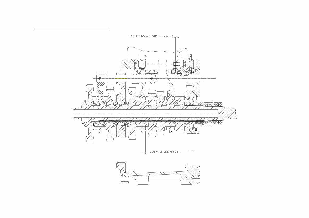
Temporarily secure the selector housing to the maincase. The dog face clearance of each ratio can now be checked, use of a small mirror is
recommended. Ideally the dog face clearance would be equal on all ratios, however this is not usually achievable, therefore the set-up target should
be to achieve minimum variations in dog face clearances across all ratios. This is achieved by grinding the fork setting adjustment spacer, (as shown
in Fig.1 on the following page.) As a guide, this thickness is usually approximately 0.120”.
Note:- It is not possible (or necessary) to individually adjust each fork
PAGE 7
© Copyright Hewland Engineering Limited
SEQUENTIAL FORK SETTING
Fig 1
0.120” Approx
PAGE 8
© Copyright Hewland Engineering Limited
H-GATE FORK SETTING
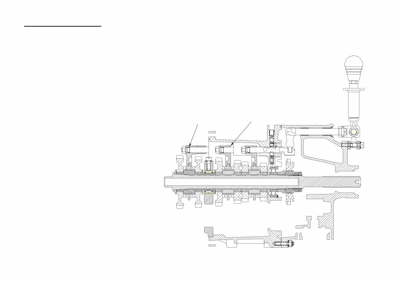
1. Heat the bearing carrier, then fit the mainshaft and layshaft bearings, reverse spigot , reverse guide pin and reverse fork spigot
Fit all relevant gear lever and gear selector finger components into the output housing. Fit the 3 selector rods, the locking pin,
balls, springs and load the shuttle pin and plungers, into their correct positions in the bearing housing. Secure the mainshaft and
layshaft bearings using the relevant circlips. Stand the maincase up on the output face ensuring all 3 selector rods are in the
neutral position. The detent springs can be shortened to achieve the desired gear shift resistance.
2. Stack the pinion bearing spacers, pinion gears, hubs and relevant clutch rings over the output shaft bore, in the correct sequence,
when the 3rd-4th and 5th-6th clutch rings are positioned, the corresponding selector fork must be fitted onto the selector rod so
that the two components are combined. Each selector rod must be fitted with a spacer (0.180” to start), and a hexagon nut lightly
tightened. Continue to build the stack, with the 1st-2nd gears, hub, spacers, clutch ring and selector fork can now be fitted, and a
selector fork spacer and hexagon nut, lightly secured to the remaining selector rod. The mainshaft can now be slid through the
stack and secured in place with the nut and locknut. In order to tighten both the mainshaft and layshaft nuts, the shafts can be
locked by engaging 2 gears at the same time. Loosen the 1st-2nd selector fork retaining nut and pull the fork towards 1st gear
until it engages, another gear can then be selected by moving the relevant selector rod.
3. Correct selection of 1st, 3rd & 5th gear can now be
achieved via modification to the relevant selector rod
spacers fitted between the selector rod and fork.
4. Correct selection of 4th & 6th gear, and the limitation
of detent over-travel, is achieved by fitting shims
between the selector fork bosses and the bearing
carrier. Similarly 2nd gear is set with the same shims
placed between the selector rod spacer and the
bearing carrier face. (NB. This spacer may need to
be reduced in length.)
5. Once all fork positions are correctly set, and the
mainshaft and layshaft lock nuts have been tightened
to the correct torques, then all selector rod nuts
can be tightened to their specified torque and fitted
using loctite retainer. It is advisable to support the
selector rod heads whilst tightening the selector fork
retaining nuts. Re-alignment of the heads and the
selector finger may be necessary to ensure smooth
operation of the selection mechanism.
Selector rod spacers
Selector rod shims
Fig 2

PAGE 9
© Copyright Hewland Engineering Limited
GEARBOX – ASSEMBLY
a/ It is assumed that all casings have been thoroughly cleaned and all bearings, oil seals, studs and dowels are already fitted.
(NB. Bearing retaining screws need to be machined to length on assembly.)
b/ Fit the oil spray tube complete with ‘o-ring’ , into the bearing carrier, and wire lock screw in position.
c/ Fit the reverse idler assembly into the bearing carrier, securing with anti rotation screw and bridge plate screws.
d/ Heat the output housing and fit oil feed tubes using loctite. (NB. Does not apply to wide “R” ratio version)
Assemble the oil pump and fit it into position in the output housing. Secure with screws, add the drive gear and the circlip.
e/ Assemble the selector barrel parts, including the reverse selector rail for the sequential version, or the selector rod
arrangement for the H-gate version.
Secure selector mechanism into relevant casings.
f/ Ensure fork setting procedure has been completed. (See previous pages for details.)
Complete assembly of all ratios into bearing carrier and secure all fasteners. Locate reverse sliding gear onto mainshaft,
and secure the reverse selector arrangement. Mainshaft locknuts, must be secured with loctite on final assembly.
(Note, loctite is not required on the SGT2 or SGTR gearbox versions, where locking rings are fitted.)
g/ Assemble the relevant components into the output housing, including the oil pump fitted with the oil pump drive gear, apply
sealing strip, and secure the housing to the bearing carrier.
h/ Heat the input housing, and fit the input bearing arrangement and the layshaft needle roller bearing. Press the taper roller
bearing inner race onto the input transfer gear and fit the remaining input assembly parts. The bearing assembly must be
adjusted so a light pre-load is felt when turning the input shaft, this is achieved by modifying the length of the pre-load spacer
positioned between the taper roller bearing inner races. The input locknut can now be fitted using loctite, to hold the assembly
whilst tightening the nut, select 2 gears simultaneously (as previously described), and temporarily bolt the input flange to the
bearing carrier with the clutch shaft bearing cover removed. The nut can then be fitted, the input flange removed from the
bearing carrier and the selector fork retaining nut secured.
I/ Fit the input wheel onto the layshaft, and secure with the nut. It is advisable to ensure that the reaction generated by
tightening this nut is pushing the transfer gears tight into mesh, and not separating them. This is important to ensure that
the bearings, shafts and housings are not over stressed by the forces generated during tightening.

PAGE 10
© Copyright Hewland Engineering Limited
CHANGING GEAR RATIOS
a/ Place a drip tray beneath the gearbox, remove the drain plug and drain the oil.
b/ Remove the nuts securing the bearing carrier to the input and output housings and use a soft hammer to tap the knock off
lugs if the housings don’t release freely, never use a screwdriver to lever between the joint faces as this may damage the
faces and the efficiency of the seals when reassembled.
c/ On an h-gate shift selection versions the 5th-6th finger stop plunger, and clevis pin will need to be removed from the output
housing to allow the selector finger to pass by the selector rod heads. On sequential shift selection versions, remove the
selector housing..
d/ Remove the mainshaft and layshaft nuts and stand the gear assembly casing down towards the output. Slide the main-
shaft and layshaft out. Remove the gears, hubs, bearings, bearing support plate, clutch rings and spacers.
e/ If only the transfer gears are to be changed then remove the clutch shaft bearing housing, engage 2 gears and remove the
input pinion locknut before removing the input flange. Once the flange is removed the input gear locknut can be removed
and the transfer gear changed.
f/ Replace the gears with the required ratios. Gears are supplied in matched pairs, one for the main shaft and one for the
layshaft. Each gear is marked with two sets of numbers, the first of these indicates the number of teeth on the input gear,
while the second indicates the number of teeth on the mainshaft gear. It is essential that the gears are correctly paired to
these numbers
g/ Whilst changing ratios it is advisable, as a matter of course, to wash and inspect all components which are to be reused
before refitting. Check for wear and cracks, particularly to the clutch rings. Also inspect the selector forks for heavy or
uneven wear.
h/ Reassembly is a reversal of disassembly.
You're Reading a Preview
What's Included?
 Lifetime Access
Fast Download Speeds
Online & Offline Access
Access PDF Contents & Bookmarks
Full Search Facility
Print one or all pages of your manual
$41.99
HEWLand Gearbox SGT Service Manual ILLUSTRATED Parts LIST
Viewed 23 Times Today

What's Included?
Lifetime Access
Fast Download Speeds
Online & Offline Access
Access PDF Contents & Bookmarks
Full Search Facility
Print one or all pages of your manual
$41.99

Secure transaction
What's Included?
Lifetime Access
Fast Download Speeds
Online & Offline Access
Access PDF Contents & Bookmarks
Full Search Facility
Print one or all pages of your manual
Description
The Hewland gearbox SGT service manual illustrated parts list is an essential resource for professional mechanics and DIY enthusiasts. This manual provides detailed information and diagrams to assist in the maintenance, repair, and assembly of the Hewland gearbox SGT. Whether you are a professional mechanic or a car enthusiast, this manual is a valuable tool for understanding the intricate components of the gearbox and ensuring proper functionality.


