

Chrysler Torqueflite Transmission Overhaul Manual
What's Included?
Fast Download Speeds
Online & Offline Access
Access PDF Contents & Bookmarks
Full Search Facility
Print one or all pages of your manual
r
Transmissions 21 - 1
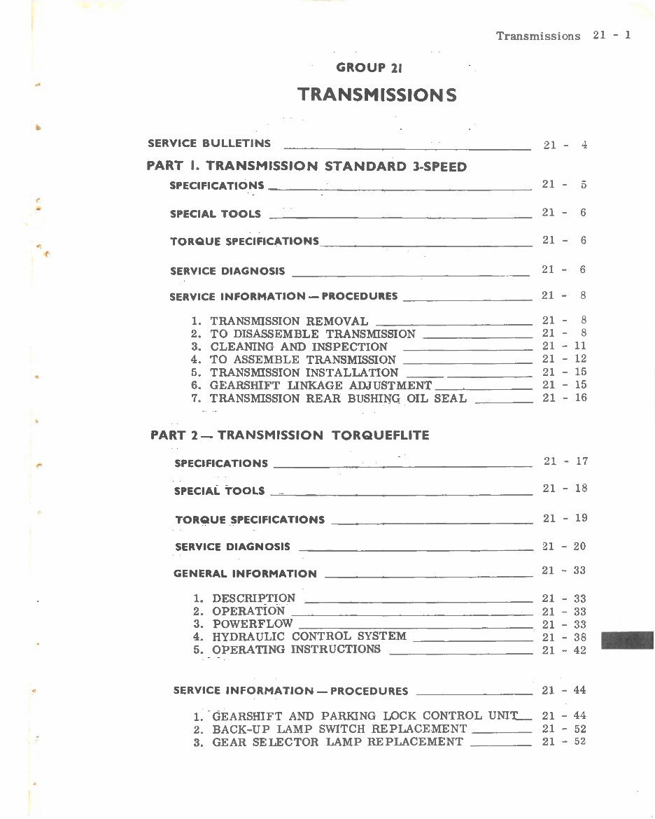
GROUP 21
TRANSMISSIONS
SERVICE BULLETINS
PART I. TRANSMISSION STANDARD 3-SPEED
SPECIFICATIONS~----------~-----
SPECIAL TOOLS
TORQUE SPECIFICATIONS ____________ _
SERVICE DIAGNOSIS ---------------
SERVICE INFORMATION- PROCEDURES --------
1. TRANSMISSION REMOVAL--~-------
2. TO DISASSEMBLE TRANSMISSION -------
3. CLEANING AND INSPECTION
4. TO ASSEMBLE TRANSMISSION --------
5. TRANSMISSION INSTALLATION
6. GEARSHIFT LINKAGE ADJUSTMENT_~----
7. TRANSMISSION REAR BUSHING OIL SEAL
PART 2- TRANSMISSION TORQUEFLITE
SPECIFICATIONS ----------------
SPECIAL TOOLS -----------------
TORQUE SPECIFICATIONS -------------
SERVICE DIAGNOSIS
GENERALINFORMATION --------------
1. DESCRIPTION
2. OPERATION ---------------
3. POWERFLOW ---------------
4. HYDRAULIC CONTROL SYSTEM -------
5. OPERATING INSTRUCTIONS
SERVICE INFORMATION- PROCEDURES
21
-
-:1:
21
-
5
21 - 6
21 -
6
21 - 6
21 -
8
21 -
8
21 - 8
21 - 11
21
- 12
21
- 15
21
- 15
21
- 16
21 - 17
21 - 18
21 - 19
21 - 20
21 - 33
21 - 33
21 - 33
21 - 33
21-38 -
21 - 42
21 - 44
1. GEARSHIFT AND PARKING LOCK CONTROL UNIT._ 21 - 44
2. BACK-UP LAMP SWITCH REPLACE- MENT 21 - 52
3. GEAR SELECTOR LAMP REPLACEMENT 21 - 52
Transmissions 21 - 2
4. GEARSHIFT CONTROL CABLE (TRANSMISSION END)
5. PARKING LOCK CABLE (TRANSMISSION END)
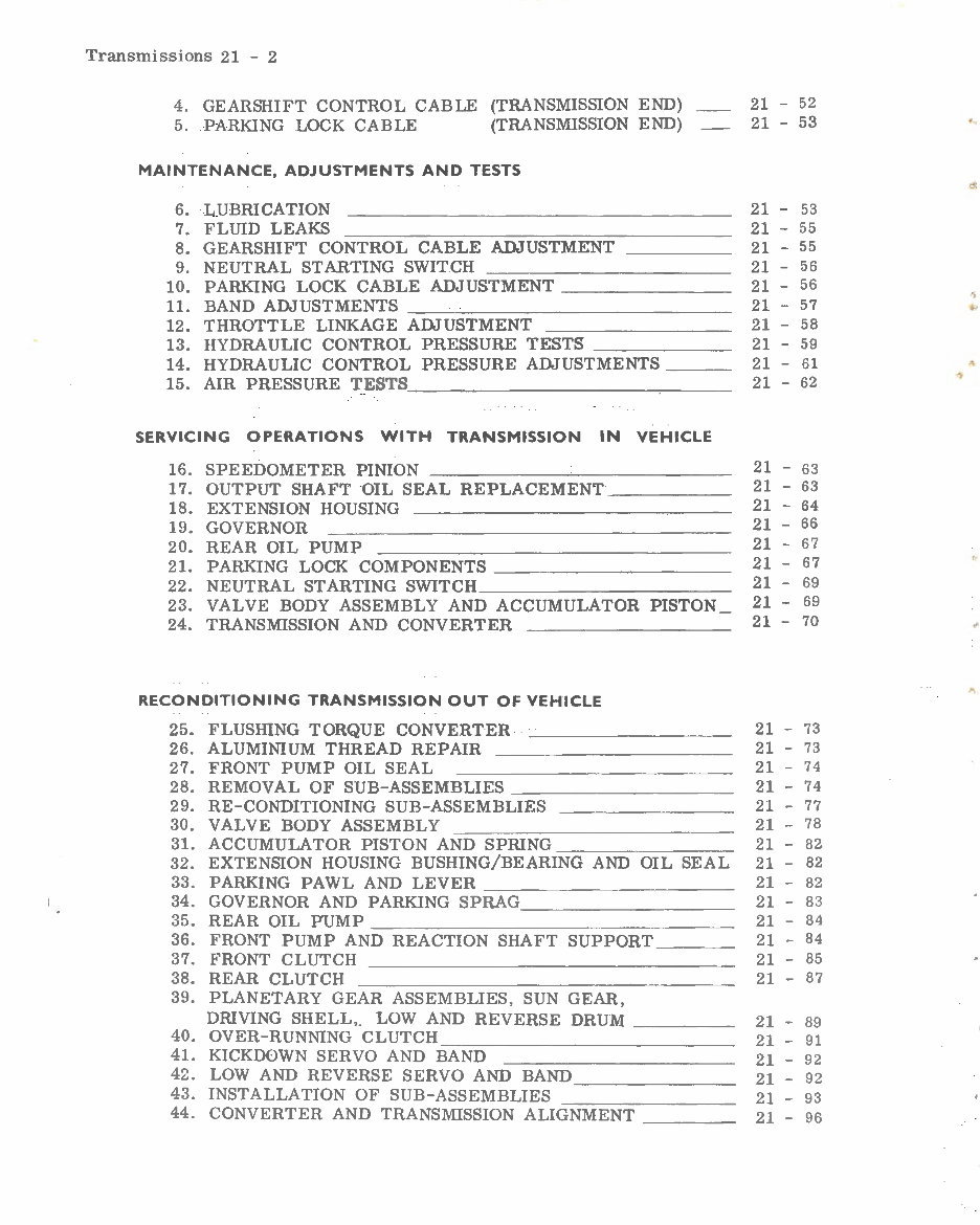
MAINTENANCE, ADJUSTMENTS AND TESTS
6. LUBRICATION
7. FLUID LEAKS
8. GEARSHIFT CONTROL CABLE ADJUSTMENT
9. NEUTRAL STARTING SWITCH
10. PARKING LOCK CABLE ADJUSTMENT
11. BAND ADJUSTMENTS
12. THROTTLE LINKAGE ADJUSTMENT
13. HYDRAULIC CONTROL PRESSURE TESTS
14. HYDRAULIC CONTROL PRESSURE ADJUSTMENTS
15. AIR PRESSURE TESTS
SERVICING OPERATIONS WITH TRANSMISSION IN VEHICLE
16. SPEEDOMETER PINION --- ------- ---
17. OUTPUT SHAFT OIL SEAL REPLACEMENT ____ _
18. EXTENSION HOUSING
19. GOVERNOR
20. REAR OIL PUMP
21. PARKING LOCK COMPONENTS--------- -
22. NEUTRAL STARTING SWITCH __________ _
23. VALVE BODY ASSEMBLY AND ACCUMULATOR PISTON
24. TRANSMISSION AND CONVERTER
RECONDITIONING TRANSMISSION OUT OF VEHICLE
25. FLUSHING TORQUE CONVERTER
26. ALUMINIUM THREAD REPAIR
27. FRONT PUMP OIL SEAL
28. REMOVAL OF SUB-ASSEMBLIES
29. RE-CONDITIONING SUB-ASSEMBLIES
30. VALVE BODY ASSEMBLY
31. ACCUMULATOR PISTON AND SPRING
32. EXTENSION HOUSING BUSHING/BEARING AND OIL SEAL
33. PARKING PAWL AND LEVER
34. GOVERNOR AND PARKING SPRAG
35. REAR OIL PUMP
36. FRONT PUMP AND REACTION SHAFT SUPPORT
37. FRONT CLUTCH
38. REAR CLUTCH
39. PLANETARY GEAR ASSEMBLIES, SUN GEAR,
DRIVING SHELL,. LOW AND REVERSE DRUM
40. OVER-RUNNING CLUTCH
41. KICKDOWN SERVO AND BAND
42. LOW AND REVERSE SERVO AND BAND
43. INSTALLATION OF SUB-ASSEMBLIES
44.
CONVERTER AND TRANSMISSION ALIGNMENT
21 - 52
21 - 53
21 - 53
21 - 55
21 -
55
21 -
56
21 -
56
21 - 57
21 - 58
21 - 59
21 - 61
21 - 62
21 - 63
21 - 63
21 - 64
21 - 66
21 - 67
21 - 67
21 - 69
21 - 69
21 - 70
21 - 73
21 - 73
21 - 74
21 - 74
21 - 77
21 -
78
21 - 82.
21 - 82
21 - 82
21 - 83
21 - 84
21 -
84
21 - 85
21 -
87
21 - 89
21 - 91
21 - 92
21 -
92
21 - 93
21 - 96
" .,
..
Transmissio ns 21 - 3
PART 3 - SERVICE REPLACEMENT BUSHING
SPECIAL TOOLS
21 - 99
SERVICE INFORMATION- PROCEDURES 21 - 99
1. GENERAL INFORMATION 21 - 99
2. BUSHING REPLACEMENT ____ 21 - 99
PART 4- STARTER RING GEAR REPLACEMENT
SERVICE INFORMATION- PROCEDURES --------- 21 - 102
1. REMOVING RING GEAR _____ 21 - 102
2. INSTALLING RING GEAR____ 21 - 102
t
Transmissions 21 - 4
SERVICE BULLETIN REFERENCE
Date Number Subject
Changes
..
4
...,
•'
Transmissions 21 - 5
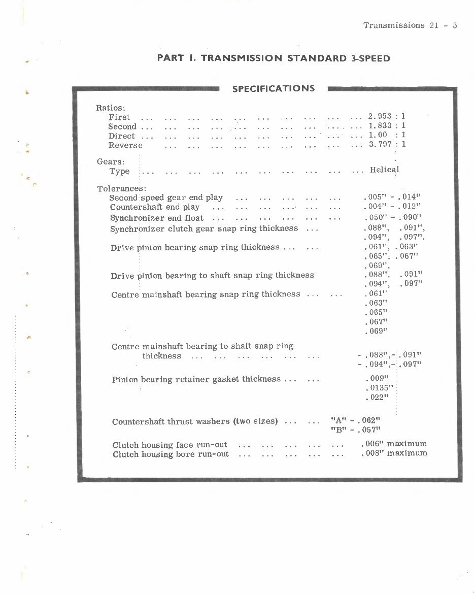
PART I. TRANSMISSION STANDARD 3-SPEED
Ratios:
First
Second
Direct
Reverse
Gears:
Type
Tolerances:
Second speed gear end play
Countershaft end play
Synchronizer end float
SPECIFICATIONS
Synchronizer clutch gear snap ring thickness
Drive pinion bearing snap ring thickness ...
Drive pinion bearing to shaft snap ring thickness
Centre mainshaft bearing snap ring thickness ...
Centre mainshaft bearing to shaft snap ring
thickness
Pinion bearing retainer gasket thickness ...
Countershaft thrust washers (two sizes)
Clutch housing face run-out
Clutch housing bore run-out
2.953 1
1. 833 1
1. 00 1
3.797 1
... Helical
. 005" - . 014"
. 004" - . 012"
. 050" - . 090"
. 088'',
. 094"'
. 061",
. 065"'
. 069
11
'
. 088"'
. 094"'
. 061
11
. 063"
. 065"
. 067"
. 069"
. 091",
. 097''.
. 063"
. 067"
. 091"
. 097"
- . 088" ,- . 091
11
- . 094" ,- . 097"
. 009"
. 0135"
. 022"
"A" - . 062"
"B" - . 057"
. 006" maximum
. 008" maximum
Transmissions 21 - 6
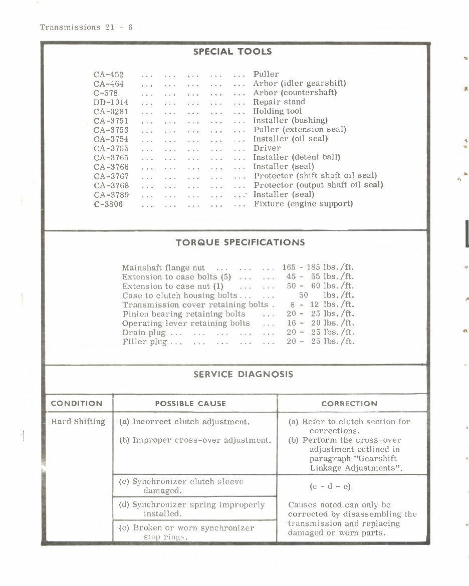
SPECIAL TOOLS
CA-452 . . . . . . . . . . .. ... Puller
CA-464 . . . . . . . . . . . . ... Arbor (idler gearshift)
C-578 . . . . . . . . . . .. ... Arbor (countershaft)
DD-1014 . . . . . . . . . . . . ... Repair stand
CA-3281 . . . . . . . . . . .. ... Holding tool
CA-3751 . . . . . . . . . . .. ... Installer (bushing)
CA-3753 . . . . . . . . . . .. ... Puller (extension seal)
CA-3754 . . . . . . . . . . .. . .. Installer (oil seal)
CA-3755 . . . . . . . . . . .. ... Driver
CA-3765 . . . . . . . . . . .. ... Installer (detent ball)
CA-3766 . . . . . . . . . . . . ... Installer (seal)
CA-3767 . . . . . . . . . . .. ... Protector (shift shaft oil seal)
CA-3768 . . . . . . . . . . . . . .. Protector (output shaft oil seal)
CA-3789 . . . . . . . . . . . . ... Installer (seal)
C-3806 . . . . . . . . . . . . ... Fixture (engine support)
CONDITION
TORQUE SPECIFICATIONS
Mainshaft flange nut . . . . . . . ..
Extension to case bolts (5) . . . . ..
Extension to case nut (1) . . . . ..
Cas e to clutch housing bolts... . ..
Transmission cover retaining bolts .
Pinion bearing retaining bolts .. .
Operating lever retaining bolts .. .
Drain plug . . . . . . . . . . . . . ..
Filler plug . . . . . . . . . . . . . ..
165 - 185 lbs. /ft.
45 - 55 lbs. /ft.
50 - 60 lbs. /ft.
50 lbs. /ft.
8 - 12 lbs. /ft.
20 - 25 lbs./ft.
16 - 20 lbs. /ft.
20 - 25 lbs. /ft.
20 - 25 lbs. /ft.
SERVICE DIAGNOSIS
POSSIBLE CAUSE CORRECTION
Hard Shifting (a) Incorrect clutch adjustment. (a) Ref er to clutch se ction f or
corrections.
(b) Improper cross-over adjustm e nt.
(c) Sy nchronizer clutch sl e eve
damaged.
(d) Synchroniz er spring improperly
installed.
(c) Brok en or worn synchronizer
s lop rings.
(b) Perform the cross-o\ ·cr
adjustment outlined in
paragraph "Gearshift
Linkage Adjustments".
(c - d - c)
Causes noted can only be
corrected by disassembling th e
transmi s sion and replacing
da m aged or worn parts.
I
I
' .
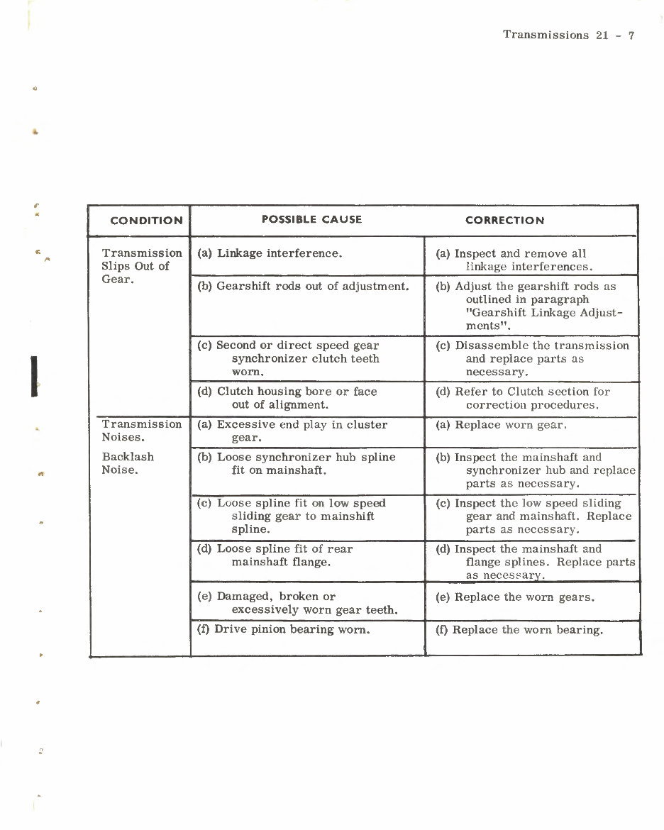
CONDITION
Transmission
Slips Out of
Gear.
Transmission
Noises.
Backlash
Noise.
POSSIBLE CAUSE
(a) Linkage interference.
(b) Gearshift rods out of adjustment.
(c) Second or direct speed gear
synchronizer clutch teeth
worn.
(d) Clutch housing bore or face
out of alignment.
(a) Excessive end play in cluster
gear.
(b) Loose synchronizer hub spline
fit on mainshaft.
(c) Loose spline fit on low speed
sliding gear to mainshift
spline.
(d) Loose spline fit of rear
mainshaft flange.
(e) Damaged, broken or
excessively worn gear teeth.
(f) Drive pinion bearing worn.
Transmissions 21 - 7
CORRECTION
(a) Inspect and remove all
linkage interferences.
(b) Adjust the gearshift rods as
outlined in paragraph
"Gearshift Linkage Adjust-
ments".
(c) Disassemble the transmission
and replace parts as
necessary.
(d) Refer to Clutch section for
correction procedures.
(a) Replace worn gear.
(b) Inspect the mainshaft and
synchronizer hub and replace
parts as necessary.
(c) Inspect the low speed sliding
gear and mainshaft. Replace
parts as necessary.
(d) Inspect the mainshaft and
flange splines. Replace parts
as neces~arv.
(e) Replace the worn gears.
(f) Replace the worn bearing.
Transmissions 21 - 8
SERVICE INFORMATION- PROCEDURES
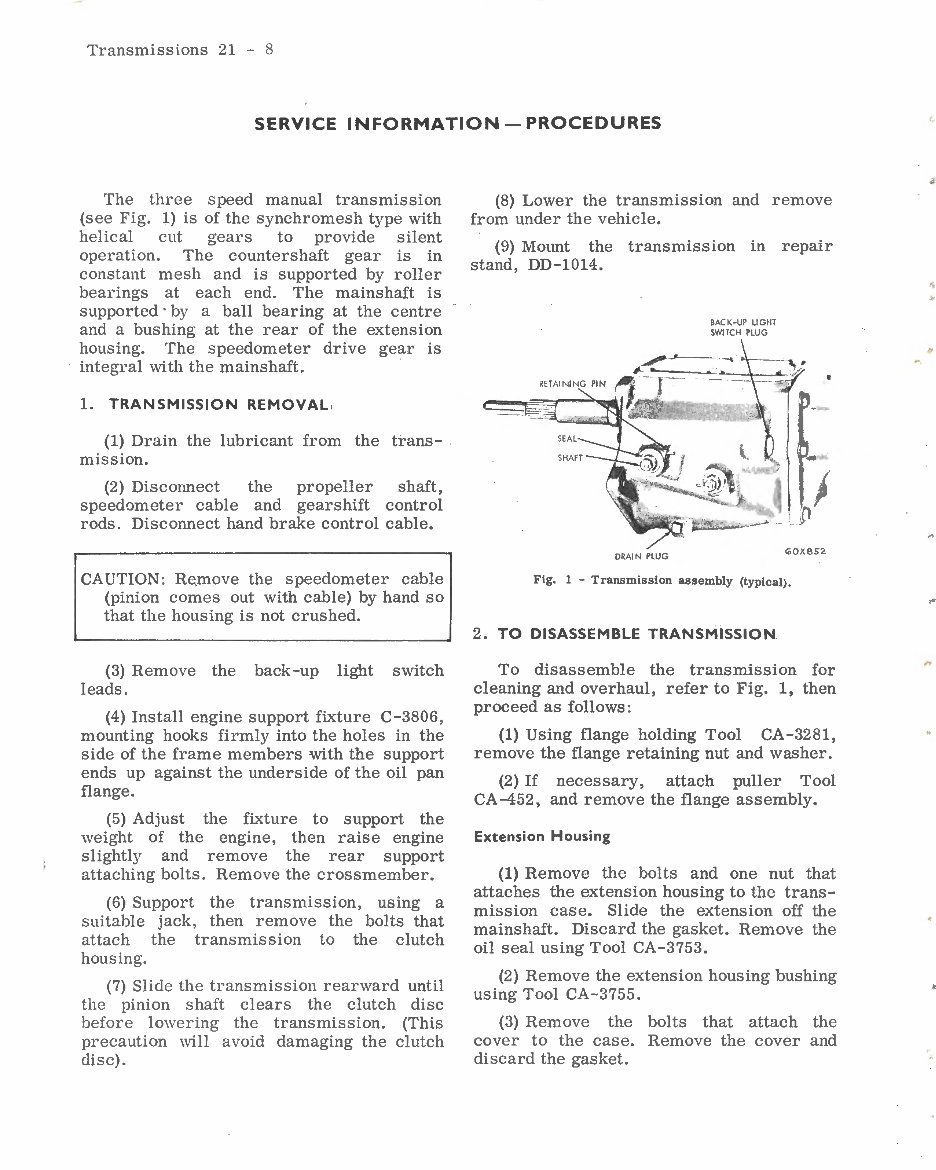
The three speed manual transmission
(see Fig. 1) is of the synchromesh type with
helical cut gears to provide silent
operation. The countershaft gear is in
constant mesh and is supported by roller
bearings at each end. The mainshaft is
supported· by a ball bearing at the centre
and a bushing at the rear of the extension
housing. The speedometer drive gear is
integral with the mainshaft.
1. TRANSMISSION REMOVAL ,
(1) Drain the lubricant from the trans-
mission.
(2) Discormect the propeller shaft,
speedometer cable and gearshift control
rods. Disconnect hand brake control cable.
CAUTION: Re, move the speedometer cable
(pinion comes out with cable) by hand so
that the housing is not crushed.
(3) Remove the back-up light switch
leads.
(4) Install engine support fixture C-3806,
mounting hooks firmly into the holes in the
side of the frame members with the support
ends up against the underside of the oil pan
flange.
(5) Adjust the fixture to support the
weight of the engine, then raise engine
slightly and remove the rear support
attaching bolts. Remove the crossmember.
(6) Support the transmission, using a
suitable jack, then remove the bolts that
attach the transmission to the clutch
housing.
(7) Slide the transmission rearward until
the pinion shaft clears the clutch disc
before lowering the transmission. (This
precaution will avoid damaging the clutch
disc).
(8) Lower the transmission and remove
from under the vehicle.
(9) Mount the transmission in repair
stand, DD-1014.
DRAIN PlUG
BAC K·UP LIGHT
SWITCH PlUG
~OX852
Fig. 1 - Transmission assembly (typical}.
2. TO DISASSEMBLE TRANSMISSION
To disassemble the transmission for
cleaning and overhaul, refer to Fig. 1, then
proceed as follows:
(1) Using flange holding Tool CA-3281,
remove the flange retaining nut and washer.
(2) If necessary, attach puller Tool
CA-452, and remove the flange assembly.
Extension Housing
(1) Remove the bolts and one nut that
attaches the extension housing to the trans-
mission case. Slide the extension off the
mainshaft. Discard the gasket. Remove the
oil seal using Tool CA-3753.
(2) Remove the extension housing bushing
using Tool CA-3755.
(3) Remove the bolts that attach the
cover to the case. Remove the cover and
discard the gasket.
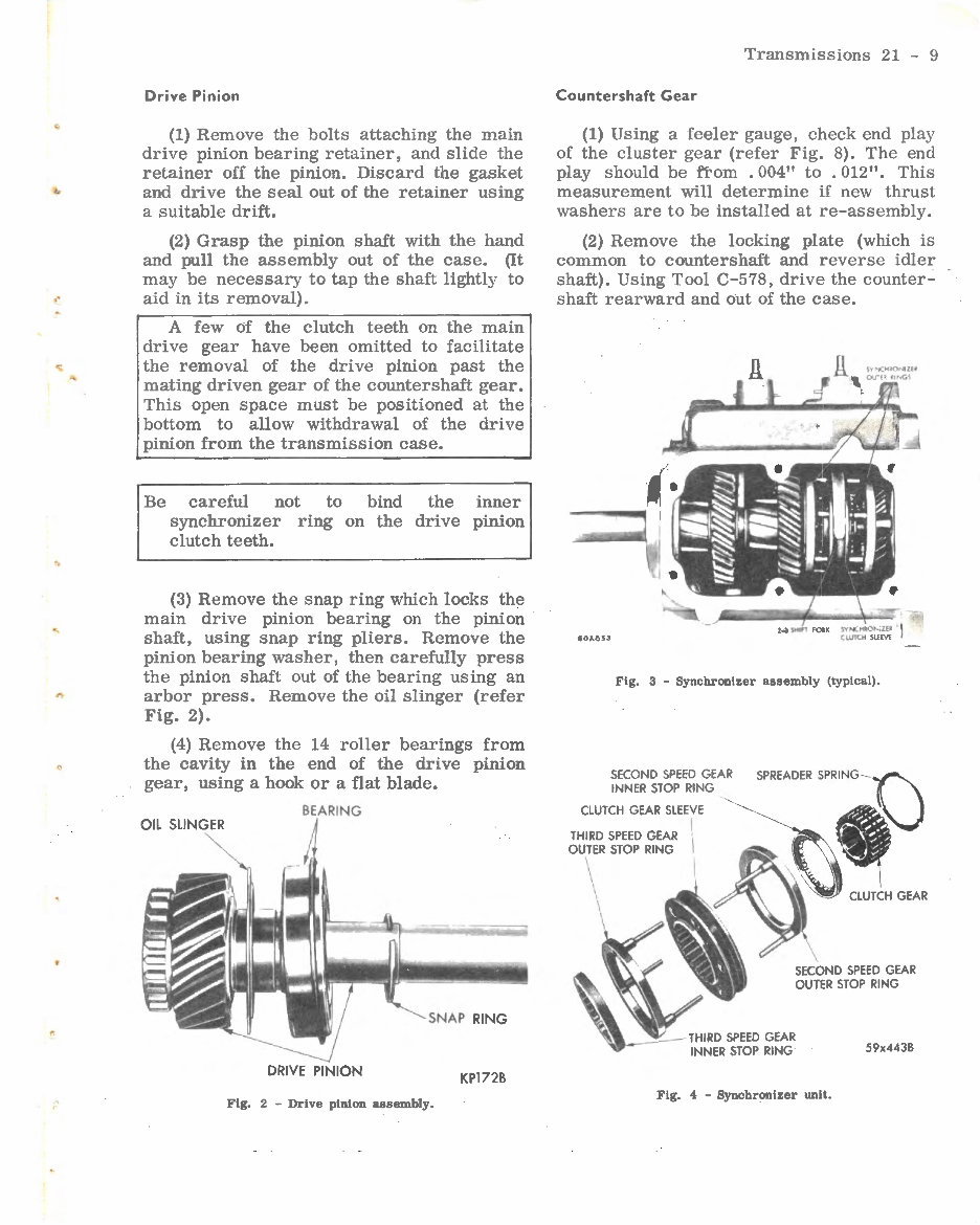
Drive Pinion
(1) Remove the bolts attaching the main
drive pinion bearing retainer, and slide the
retainer off the pinion. Discard the gasket
and drive the seal out of the retainer using
a suitable drift.
(2) Grasp the pinion shaft with the hand
and pull the assembly out of the case. (It
may be necessary to tap the shaft lightly to
aid in its removal).
A few of the clutch teeth on the main
drive gear have been omitted to facilitate
the removal of the drive pinion past the
mating driven gear of the counter shaft gear.
This open space must be positioned at the
bottom to allow withdrawal of the drive
pinion from the transmission case.
Be careful not to bind the inner
synchronizer ring on the drive pinion
clutch teeth.
(3) Remove the snap ring which locks the
main drive pinion bearing on the pinion
shaft, using snap ring pliers. Remove the
pinion bearing washer, then carefully press
the pinion shaft out of the bearing using an
arbor press. Remove the oil slinger (refer
Fig. 2).
(4) Remove the 14 roller bearings from
the cavity in the end of the drive pinion
gear, using a hook or a flat blade.
BEARING
OIL SLINGER
DRIVE PINION
KP172B
Fig. 2 - Drive pinion assembly.
Transmiss ions 21 - 9
Countershaft Gear
(I) Using a feeler gauge, chec k end play
of the cluster gear (refer Fig. 8). Th e end
play should be ftom . 004'' to . 012". Th is
measurement will determine if new thru st
washers are to be installed at re - as s embly.
(2) Remove the locking plate (whi ch is
common to countershaft and reve r se idler
shaft). Using Tool C-578, drive th e count er -
shaft rearward and out of the ca se .
Fig. 3 - Synchronizer assembly (typical).
SECOND SPEED GEAR
INNER STOP RING
CLUTCH GEAR SLEEVE
THIRD SPEED GEAR
OUTER STOP RING
Fig. 4 - Synchronizer unit.
59x443B
Transmissions 21 - 10
SPEED GEAl
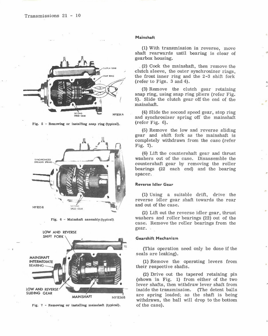
Fig. 5 - Removlng or installlng snap rlng (typlcal).
SY NCHRONIZER
SPREADER SPRING
NY8558
·-
Flg. 6 - Mainshaft assembly. (typical) .
LOW AND REVERSE
SHIFT FORK
LOW AND REVERSE
SLIDING GEAR
NY8568
Fig. 7 - Removing or installing mainshaft (typical).
Hains haft
(1) With transmission in reverse, move
shaft rearwards until bearing is clear of
gearbox housing.
(2) Cock the mainshaft, then remove the
clutch sleeve, the outer synchronizer rings,
the front inner ring and the 2 -3 shift fork
(refer to Figs. 3 and 4).
(3) Remove the clutch gear retaining
snap ring, using snap ring pliers (refer Fig.
5). Slide the clutch gear off the end of the
mains haft.
(4) Slide the second speed gear, stop ring
and synchronizer spring off the mainshaft
(refer Fig. 6).
(5) Remove the low and reverse sliding
gear and shift fork as the mainshaft is
completely withdrawn from the case (refer
Fig. 7).
(6) Lift the countershaf t gear and thrust
washers out of the case. Disassemble the
countershaft gear by removing the roller
bearings (22 each end) and the bearing
spacer.
Reverse Idler Gear
(1) Using a suitable drift, drive the
reverse idler gear shaft towards the rear
and out of the case.
(2) Lift out the reverse idler gear, thrust
washers and roller bearings (22) out of the
case. Remove the roller bearings from the
gear.
Gearshift Mechanism
(This operation need only be done if the
seals are leaking).
(1) Remove the operating levers from
their respective shafts.
(2) Drive out the tapered retaining pin
(shown in Fig. 1) from either of the two
lever shafts, then withdraw lever shaft from
inside the transmission. (The detent balls
are spring loaded; as the shaft is being
withdrawn, the ball will drop to the bottom
of the case).
6'
..
,.
..
You're Reading a Preview
What's Included?
Fast Download Speeds
Online & Offline Access
Access PDF Contents & Bookmarks
Full Search Facility
Print one or all pages of your manual
$27.99
Viewed 48 Times Today


Secure transaction
What's Included?
Fast Download Speeds
Online & Offline Access
Access PDF Contents & Bookmarks
Full Search Facility
Print one or all pages of your manual
$27.99
Suitable for both home workshop mechanics and professional technicians, this Chrysler Torqueflite Automatic Transmission Overhaul Manual provides easy step-by-step instructions and numerous diagrams. It is specifically designed for the Chrysler Torqueflite transmission.
The manual covers a wide range of topics, including:
- Fully bookmarked & interactive index
- Specifications
- Special Tools
- Torque Specifications
- Service Diagnostics
- General Information
- Description
- Operation
- Power Flow
- Hydraulic Control System
- Operating Instructions
- Service Information - Procedures
- Gear Shift & Parking Lock Control Unit
- Backup Lamp Switch Replacement
- Gear Selector Lamp Replacement
- Gear Shift Control Cable
- Parking Lock Cable
- Maintenance, Adjustments & Tests
- Lubrication
- Fluid Leaks
- Gear Shift Control Cable Adjustment
- Neutral Starting Switch
- Parking Lock Cable Adjustment
- Band Adjustments
- Throttle Linkage Adjustment
- Hydraulic Control Pressure Tests
- Hydraulic Control Pressure Adjustments
- Air Pressure Tests
- Servicing Operations with Transmission in Vehicle
- Speedometer Pinion
- Output Shaft Oil Seal Replacement
- Extension Housing
- Governor
- Rear Oil Pump
- Parking Lock Components
- Neutral Starting Switch
- Valve Body Assembly and Accumulator Piston
- Transmission & Converter
- Reconditioning Transmission out of Vehicle
- Flushing Torque Converter
- Aluminum Thread Repair
- Front Pump Oil Seal
- Removal of Sub Assemblies
- Reconditioning Sub Assemblies
- Valve Body Assembly
- Accumulator Piston & Spring
- Extension Housing Bushing/Bearing and Oil Seal
- Parking Pawl & Lever
- Governor & Parking Sprag
- Rear Oil Pump
- Front Pump & Reaction Shaft Support
- Front Clutch
- Rear Clutch
- Planetary Gear Assemblies, Sun Gear, Driving Shell, Low and Reverse Drum
- Overrunning Clutch
- Kick Down Servo and Band
- Low and Reverse Servo and Band
- Installation of Sub Assemblies
- Converter and Transmission Alignment
- Removal of Ring Gear
- Installing Ring Gear


