

41TE & 62TE Automatic Transmission Workshop Service Manual
What's Included?
Fast Download Speeds
Offline Viewing
Access Contents & Bookmarks
Full Search Facility
Print one or all pages of your manual
2009 AUTOMATIC TRANSMISSION
62TE - Service Information - Grand Caravan, Town & Country
DESCRIPTION
DESCRIPTION
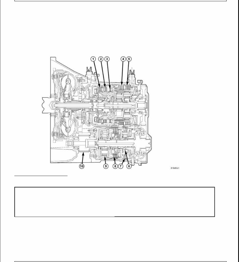
Fig. 1: 62TE Transmission
Courtesy of CHRYSLER LLC
The planetary gear train for the 62TE transaxle provides six forward gear ratios, including two fourth gear
ratios. One reverse gear ratio is also provided.
Underdrive (UD) Compounder Assembly
Low Clutch (LC)
Direct Clutch (DC)
1 - Underdrive Clutch (UD) 6 - Overrunning Clutch (ORC)
2 - Overdrive Clutch (OD) 7 - Low Clutch (LC)
3 - Reverse Clutch (R) 8 - Direct Clutch (DC)
4 - 2/4 Clutch 9 - Planetary Gear Set
5 - L/R Clutch 10 - Remote Pinion Gear
Overrunning Clutch (ORC)
Planetary gear set
Fore-Mounted Valve Body/Solenoid/Pressure Switch Assembly
DC solenoid
LC solenoid
DC pressure switch
LC pressure switch
Torque Converter Clutch (TC) and pressure control Solenoids
Line Pressure Sensor (LPS)
An additional (third) speed sensor
A "squashed," or flatter, torque converter
A flatter oil pump
A new cover for valve body access
23-way connector for the Solenoid/Pressure Switch Assembly
Redesigned transfer gears with an oil scavenger
A remote pinion gear
A 2-piece, closed differential case with structural clamshell housing.
The addition of the underdrive compounder assembly components improves low-end torque multiplication,
enhancing low-end power capability.
TRANSAXLE IDENTIFICATION
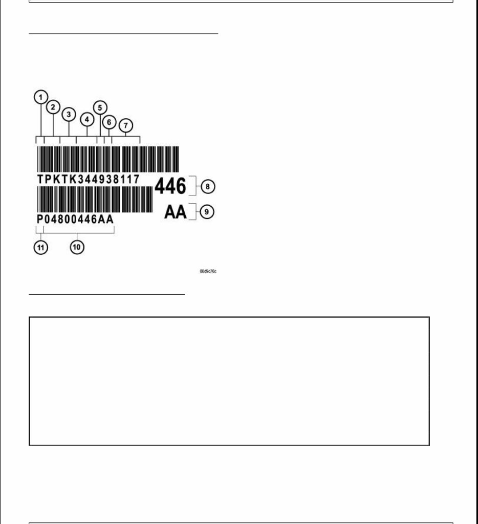
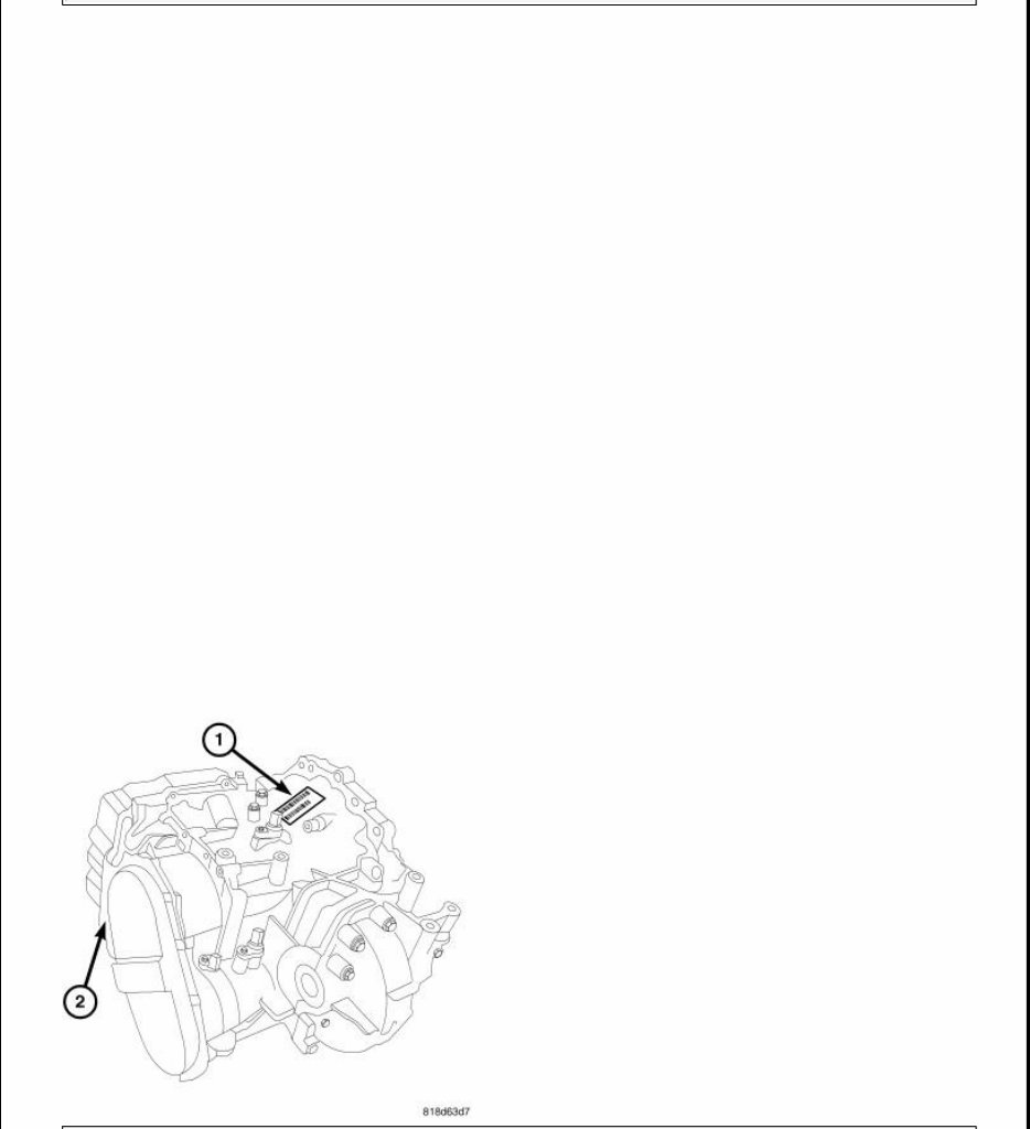
Fig. 2: Case Stamp & Bar Code Label Location
Courtesy of CHRYSLER LLC
The 62TE transaxle is identified by a barcode label (1) that is fixed to the transaxle or the "PK" number (2).
Fig. 3: Identification Label Breakdown
Courtesy of CHRYSLER LLC
The label contains a series of digits that can be translated into useful information such as transaxle part number,
date of manufacture, manufacturing origin, plant shift number, build sequence number, etc. Refer to for
identification label breakdown.
If the tag is not legible or missing, the "PK" number, which is stamped into the transaxle case behind the
transfer gear cover, can be referred to for identification. This number differs slightly in that it contains the entire
1 - T=TRACEABILITY
2 - SUPPLIER CODE (PK=KOKOMO)
3 - COMPONENT CODE (TK=KOKOMO TRANSMISSION)
4 - BUILD DAY (344=DEC. 9)
5 - BUILD YEAR (9=1999)
6 - LINE/SHIFT CODE (3=3RD SHIFT)
7 - BUILD SEQUENCE NUMBER
8 - LAST THREE OF P/N
9 - ALPHA
10 - TRANSAXLE PART NUMBER
11 - P=PART NUMBER
transaxle part number, rather than the last three digits.
OPERATION
OPERATION
ELEMENTS IN USE AT EACH POSITION OF SELECTOR LEVER
A = Applied
H = Holding
* = Limp-in Mode
^ = Applied in coast only
In total, the 62TE provides seven forward ratios and one reverse.
The underdrive compounder assembly has two modes of operation: direct and reduction.
Notice in the "What's On When" chart, the 2-3, 3-2, and 4-2 shifts require a "double swap" shift. This occurs
when two elements are turned off while two different elements are engaged.
This clutch-to-clutch synchronization takes place within 40 - 70 milliseconds, producing a smooth shift. If the
underdrive compounder assembly shifts too early (in relation to the shifts taking place in the main centerline), a
shudder or harsh shift results. If the underdrive assembly shifts too late, the driver experiences a "double bump"
sensation.
To avoid a double swap shift in a 6-4 downshift, the transaxle shifts into 4th prime, which requires the
deactivation of the OD clutch and the simultaneous application of the UD clutch.
REVERSE GEAR
62TE ELEMENTS APPLIED
GEAR RATIO UD OD R 2-4 L-R LC DC ORC
1 4.127 A - - - A A ^ - H
2 2.842 A - - - A - A -
3* 2.284 A - - A - A ^ - H
4 1.573 A - - A - - A -
4 1.452 A A - - - A ^ - H
5 1.000 A A - - - - A -
6 0.689 - A - A - - A -
R 3.215 - - A - A A - -
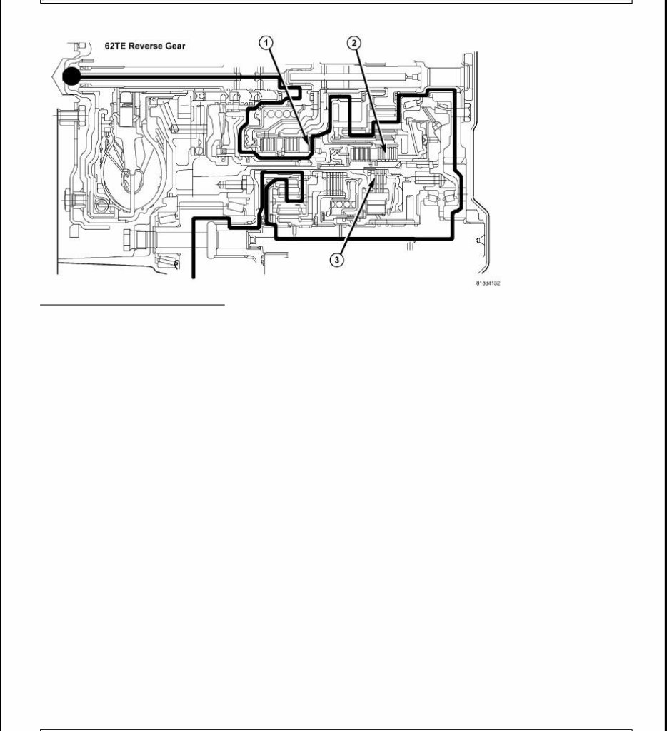
Fig. 4: Reverse Gear Power Flow
Courtesy of CHRYSLER LLC
In Reverse, the Reverse Clutch (R) (1) is applied to provide input torque. The reverse clutch drives the front sun
gear. The L/R clutch (2) is applied to hold the front carrier/rear annulus assembly. The rear carrier/front annulus
assembly rotates as an output member in reverse with a reduction gear ratio of 2.21:1.
Power from the main centerline transfers to the underdrive compounder annulus by way of the transfer gears
and the underdrive shaft. The Low Clutch (LC) (3) is applied to hold the underdrive compounder sun gear. With
the sun gear held, the annulus drives the underdrive compounder carrier, and a reduction gear ratio of 1.45:1 is
achieved
The main centerline ratio of 2.21:1 is multiplied by the underdrive compounder centerline ratio of 1.45:1. As a
result, the ratio through the entire gear train to the final drive in Reverse is 3.215:1.
FIRST GEAR
You're Reading a Preview
What's Included?
Fast Download Speeds
Offline Viewing
Access Contents & Bookmarks
Full Search Facility
Print one or all pages of your manual
$40.99
Viewed 20 Times Today


Secure transaction
What's Included?
Fast Download Speeds
Offline Viewing
Access Contents & Bookmarks
Full Search Facility
Print one or all pages of your manual
$40.99
This workshop service repair manual covers the following automatic transmissions:
- 6-Speed Automatic Transmission 62TE
- 4-Speed Automatic Transmission 41TE
The manual includes the following content:
- Description
- Transaxle Identification
- Operation
- Diagnosis and Testing
- Torque Converter Housing Fluid Leakage
- Removal
- Disassembly
- Assembly
- Differential Cover Bolts
- Installation
- Solenoid Connector at Transmission
- Gear Train Measurements
- Torque Specifications
- Special Tools
- Accumulator
- Underdrive Clutch Piston, Spring & Retainer
- Snap Ring
- Spring Retainer
- Spring
- UD Clutch Piston
- Seal, Outer
- Seal, Inner
- Input Clutch Assembly
- Overdrive Shaft
- Assembly, Transmission Solenoid and Pressure Switch
- Cable, Shift
- Schematics and Diagrams
This comprehensive manual is available in .PDF format and features detailed exploded views. It is a valuable resource used by professional mechanics and DIY enthusiasts for gearbox repairs, maintenance, and servicing. The manual provides step-by-step procedures with illustrations, making it fully printable for selected pages or the entire manual.


