CONTENTS Preparation Page 4 Connecting the Essentials (EFI) Page 5 Connecting the Essentials (CARB) Page 6 Setting up the Quick 1 Page 8 Notes on Installation Page 10 Transmission Diagrams Page 12 Optional Accessories Page 14 Manual Shift Connections Overview Page 16 Manutronic Jumper Page 16 Push-buttons + On/Off Toggle Page 17 Push-buttons + On/Off Push-button Page 18 Shrifter TM Receiver Page 19 Shiftware Introduction Page 20 Setup Page 20 Customize Page 21 Tables Page 22 Save & Load Page 22 Writing a Calibration Page 22 Important Information Page 23 Troubleshooting Page 24 Contact Page 24 READ BEFORE PROCEEDING Before installing the Quick 1 unit, we recommend you read the manual from beginning to end. Some of the information in this manual is very important and, if the unit is improperly installed or an error code misunderstood, could result in serious damage to your vehicle and transmission. 3
PREPARATION 4L60E Transmission: The Quick 1 TCS currently supports 1996 and newer 4L60E transmissions. Support for the 1993-95 is planned in the near future. 4L80E Transmission: Pre-1993 4L80E transmissions use a different internal wiring harness and pass- through connector. This early harness has a problem with leaking fluid at the pass-through connector. GM recommends upgrading to the newer connector and wiring harness. Because of this, we do not provide a wiring harness for it. If you have one of these early transmissions, it will be necessary to upgrade to the 1993+ internal wiring harness. The Bosch pressure control solenoid used in pre-1994 4L80E transmissions is not compatible with the Quick 1 TCS. You will need to upgrade it to the 1994+ Holley solenoid. The older Bosch solenoid is silver, while the newer Holley solenoid is black. If your solenoid is already black, you have the right one and it doesn't need to be changed. The GM part number for the Holley pressure control solenoid is 8684216. 4
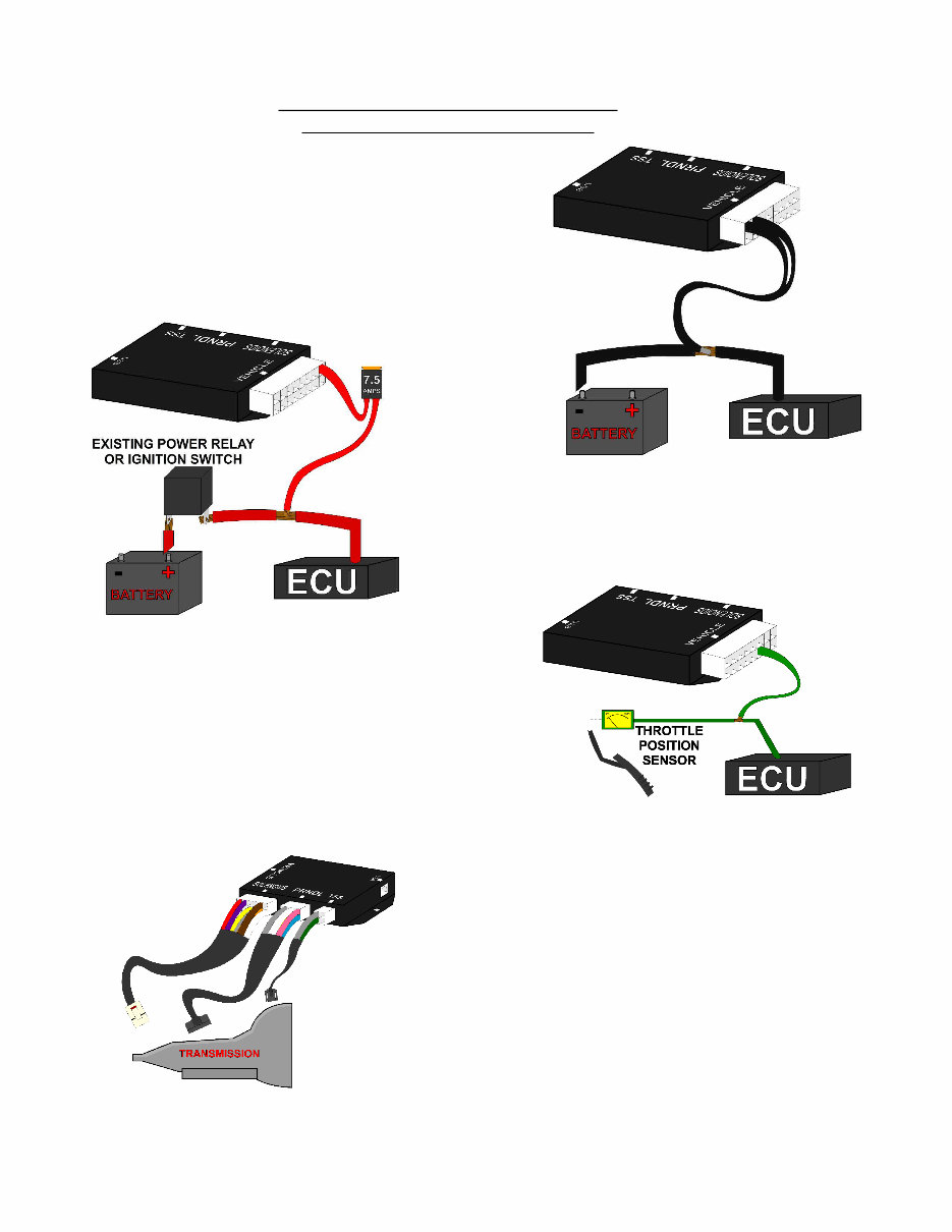
CONNECTING THE ESSENTIALS (ELECTRONIC FUEL INJECTION) Step 1: Ground Splice the ground wires (Pins 15 & 16 Black) from the Quick 1 into the main ECU (Engine Control Unit) ground wire. Do NOT connect the ground wires to sheet metal or other ground sources. The Quick 1 MUST be connected to the Main ECU ground, as close to the ECU as possible. Step 2: Power Splice the power wire (Pin 9 Red with 7.5 Amp fuse) from the Quick 1 into the main ECU (Engine Control Unit) ignition-switched power wire. Step 3: Throttle Position Sensor or Accelerator Pedal Position Sensor Splice the Throttle Position Sensor signal wire (Pin 3 Green) from the Quick 1 into the Throttle Position Sensor (TPS) signal input of the ECU (Engine Control Unit). If the vehicle has Electronic Throttle Control, use the Accelerator Pedal Position (APP) Sensor instead of the TPS. Step 4: Transmission Connectors Connect the Solenoid, PRNDL, and TSS cables to the transmission. Additionally, connect the Neutral Safety Switch and the Backup Lamp Switch. Step 5: Accessories Connect the optional accessories you wish to use. See the "Optional Accessories" section for details. 5
The Hydra-matic 4L60-E Technicians Guide is designed for automotive technicians with a good understanding of automatic transaxle or transmission operations. It may be challenging for those without prior knowledge in this area. The publication aims to explain fundamental mechanical, hydraulic, and electrical operating principles using industry-specific technical terms. Additionally, it includes a Glossary for commonly associated words.
This guide is also meant to support technicians in servicing, diagnosing, and repairing the 4L60-E transaxle. However, it is not a replacement for other General Motors service publications typically used in the field. As repair procedures and technical specifications vary across vehicles and transmission models, the relevant service publication should be consulted for servicing the Hydra-matic 4L60-E transmission. The guide spans 150 color pages.