

Chevrolet 4L60/4L60E Transmission Service & Repair Manual + Parts Catalog
What's Included?
Fast Download Speeds
Offline Viewing
Access Contents & Bookmarks
Full Search Facility
Print one or all pages of your manual

Installation and Operation Manual for
4L60/4L80 transmissions

US Shift Transmission Control System (TCS) instruction and operation manual.
www.USshift.com
Baumann Electronic Controls, LLC.
207 Mistr Lane, Pickens, SC 29671
Phone: (864) 646-8920 FAX: (864) 335-9055
Email: sales.tech@becontrols.com
This work, and the ideas and processes contained herein are the exclusive property of
Baumann Electronic Controls, LLC, and may not be copied, reproduced or distributed
in any form without the express written consent of Baumann Electronic Controls,
LLC or Karl Baumann. The technology and processes contained in this product are
proprietary and may be used only on a single unit basis or as defined by the written
permission of Baumann Electronic Controls, LLC.
V4.2 © Copyright 1997 - 2010 by Baumann Electronic Controls, LLC.
All rights reserved.
WARRANTY:
Baumann Electronic Controls, LLC. is dedicated to producing the highest quality
products available in the industry and is committed to customer satisfaction.
Because we have no control over the circumstances under which our products are
used, we can assume no more responsibility for damages (consequential or
otherwise) or defects in materials and workmanship than the original purchase
price of our product. Baumann Electronic Controls, LLC. will repair or replace all
defective components unconditionally for a period of five years from the date of
sale. This Warranty does not cover damages due to abuse or improper application
or connection of the device. After the Warranty period, Baumann Electronic
Controls, LLC. will service this device for a nominal fee.
APPLICATION COVERAGE
This system works with all 4L60E/4L65/4L80E/4L85 automatic transmissions.
It is recommended that you use the Baumann wiring harness with this system.
2

CONTENTS
Preparation Page 4
Connecting the Essentials (EFI) Page 5
Connecting the Essentials (CARB) Page 6
Setting up the Quick 1 Page 8
Notes on Installation Page 10
Transmission Diagrams Page 12
Optional Accessories Page 14
Manual Shift Connections
Overview Page 16
Manutronic Jumper Page 16
Push-buttons + On/Off Toggle Page 17
Push-buttons + On/Off Push-button Page 18
Shrifter
TM
Receiver Page 19
Shiftware
Introduction Page 20
Setup Page 20
Customize Page 21
Tables Page 22
Save & Load Page 22
Writing a Calibration Page 22
Important Information Page 23
Troubleshooting Page 24
Contact Page 24
READ BEFORE PROCEEDING
Before installing the Quick 1 unit, we recommend you read the manual from
beginning to end. Some of the information in this manual is very important and,
if the unit is improperly installed or an error code misunderstood, could result in
serious damage to your vehicle and transmission.
3

PREPARATION
4L60E Transmission:
The Quick 1 TCS currently supports 1996 and newer 4L60E transmissions.
Support for the 1993-95 is planned in the near future.
4L80E Transmission:
Pre-1993 4L80E transmissions use a different internal wiring harness and pass-
through connector. This early harness has a problem with leaking fluid at the
pass-through connector. GM recommends upgrading to the newer connector
and wiring harness. Because of this, we do not provide a wiring harness for it. If
you have one of these early transmissions, it will be necessary to upgrade to the
1993+ internal wiring harness.
The Bosch pressure control solenoid used in pre-1994 4L80E transmissions is
not compatible with the Quick 1 TCS. You will need to upgrade it to the 1994+
Holley solenoid. The older Bosch solenoid is silver, while the newer Holley
solenoid is black. If your solenoid is already black, you have the right one and it
doesn't need to be changed. The GM part number for the Holley pressure
control solenoid is 8684216.
4
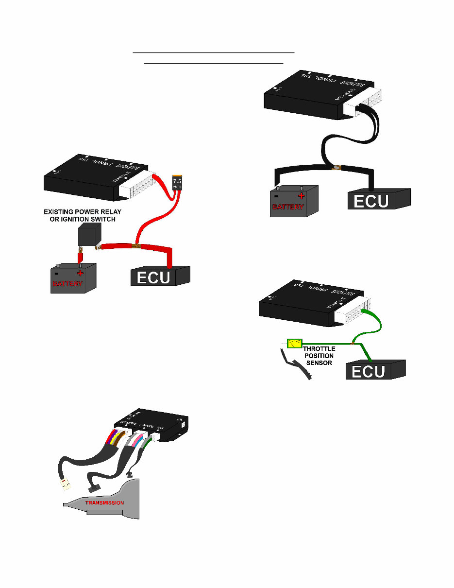
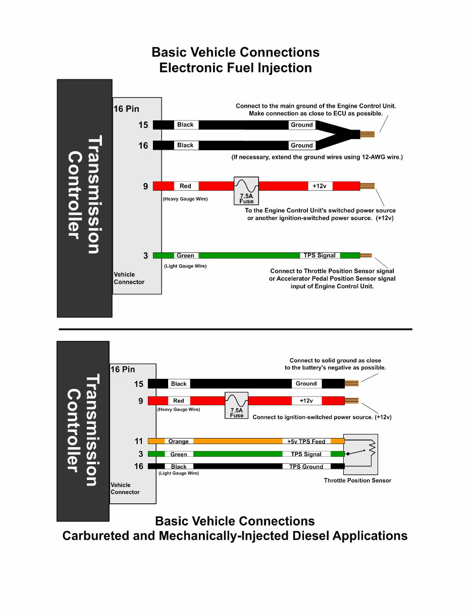
CONNECTING THE ESSENTIALS
(ELECTRONIC FUEL INJECTION)
Step 1: Ground
Splice the ground wires (Pins 15 & 16 Black) from
the Quick 1 into the main ECU (Engine Control Unit)
ground wire. Do NOT connect the ground wires to
sheet metal or other ground sources. The Quick 1
MUST be connected to the Main ECU ground, as
close to the ECU as possible.
Step 2: Power
Splice the power wire (Pin 9 Red with 7.5 Amp fuse)
from the Quick 1 into the main ECU (Engine Control
Unit) ignition-switched power wire.
Step 3: Throttle Position Sensor
or Accelerator Pedal Position Sensor
Splice the Throttle Position Sensor signal wire (Pin 3
Green) from the Quick 1 into the Throttle Position
Sensor (TPS) signal input of the ECU (Engine
Control Unit). If the vehicle has Electronic Throttle
Control, use the Accelerator Pedal Position (APP)
Sensor instead of the TPS.
Step 4: Transmission Connectors
Connect the Solenoid, PRNDL, and
TSS cables to the transmission.
Additionally, connect the Neutral Safety
Switch and the Backup Lamp Switch.
Step 5: Accessories
Connect the optional accessories you wish to use.
See the "Optional Accessories" section for details.
5
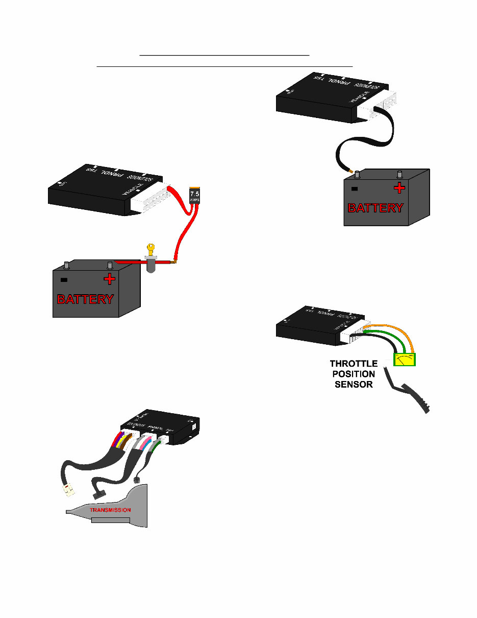
CONNECTING THE ESSENTIALS
(CARBURETED AND MECHANICALLY-INJECTED DIESEL)
Step 1: Ground
Connect the ground wire (Pin 15 Black) from the
Quick 1 directly to the battery ground post or
negative battery cable. Do NOT connect the ground
wire to sheet metal or other ground sources. The
Quick 1 MUST be connected directly to the battery
ground post or negative battery cable.
Step 2: Power
Connect the power wire (Pin 9 Red with 7.5 Amp
fuse) from the Quick 1 to ignition-switched power
wire. Do NOT use accessory-switched power.
Step 3: Throttle Position Sensor
Attach the 3 Throttle Position wires from the Quick 1
to the Throttle Position Sensor. Pin 16 Black is
dedicated ground. Pin 11 Orange is +5v reference
feed. Pin 3 Dark Green is the position sensor signal.
See the "Throttle Position Sensor" section for details.
Step 4: Transmission Connectors
Connect the Solenoid, PRNDL, and
TSS cables to the transmission.
Additionally, connect the Neutral Safety
Switch and the Backup Lamp Switch.
Step 5: Accessories
Connect the optional accessories you wish to use.
See the "Optional Accessories" section for details.
6
7
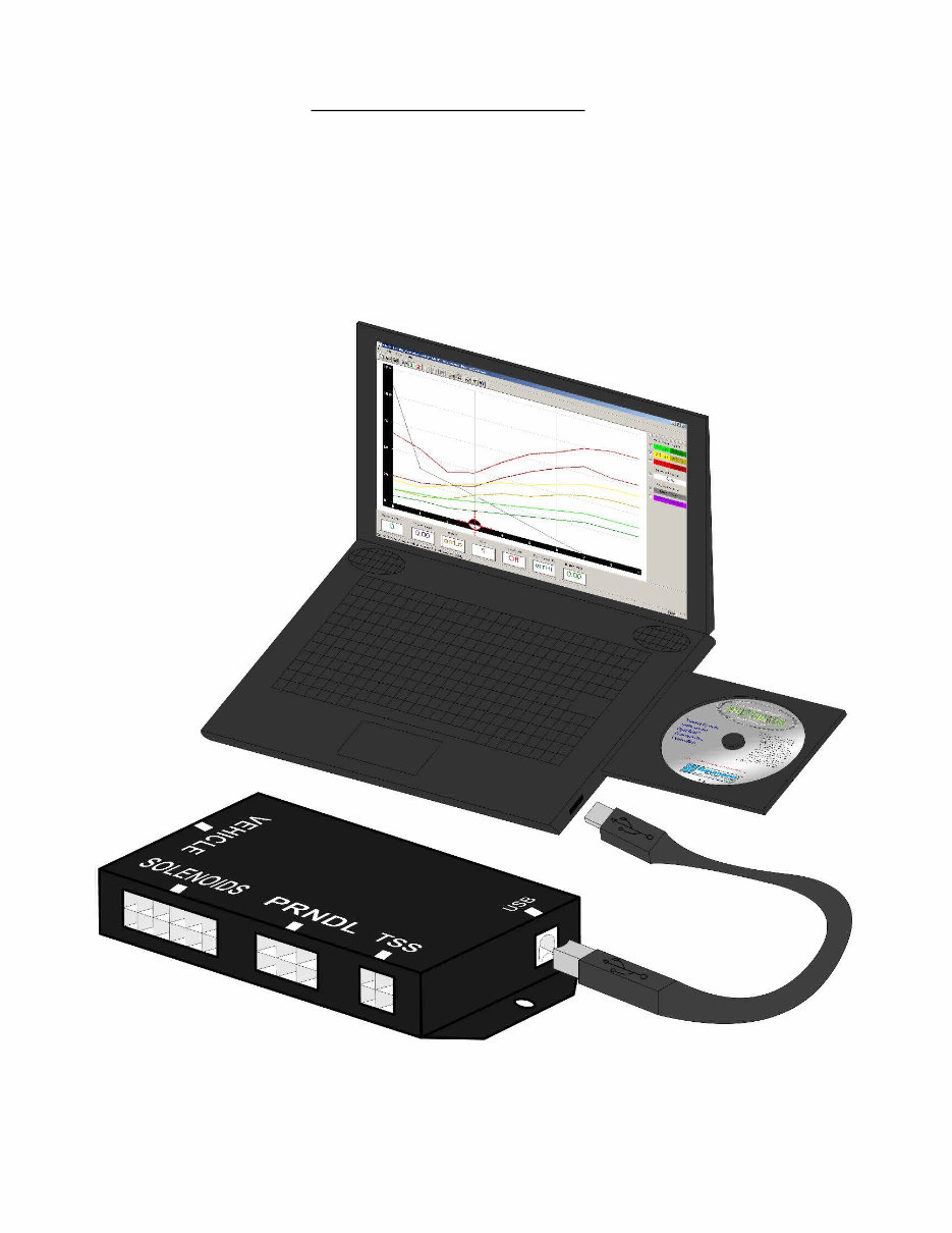
SETTING UP THE QUICK 1
Step 6: Calibration
Verify that the correct calibration is loaded on the Quick 1. A standard calibration
specific to your order is loaded before shipment. However, if the transmission
configuration has changed since the order was placed, you'll need to connect
the Quick 1 to a Windows PC and install the Shiftware Tuning Software. (See
the “Shiftware” section for installation instructions.) Using the software, load the
calibration that matches your transmission's configuration.
8
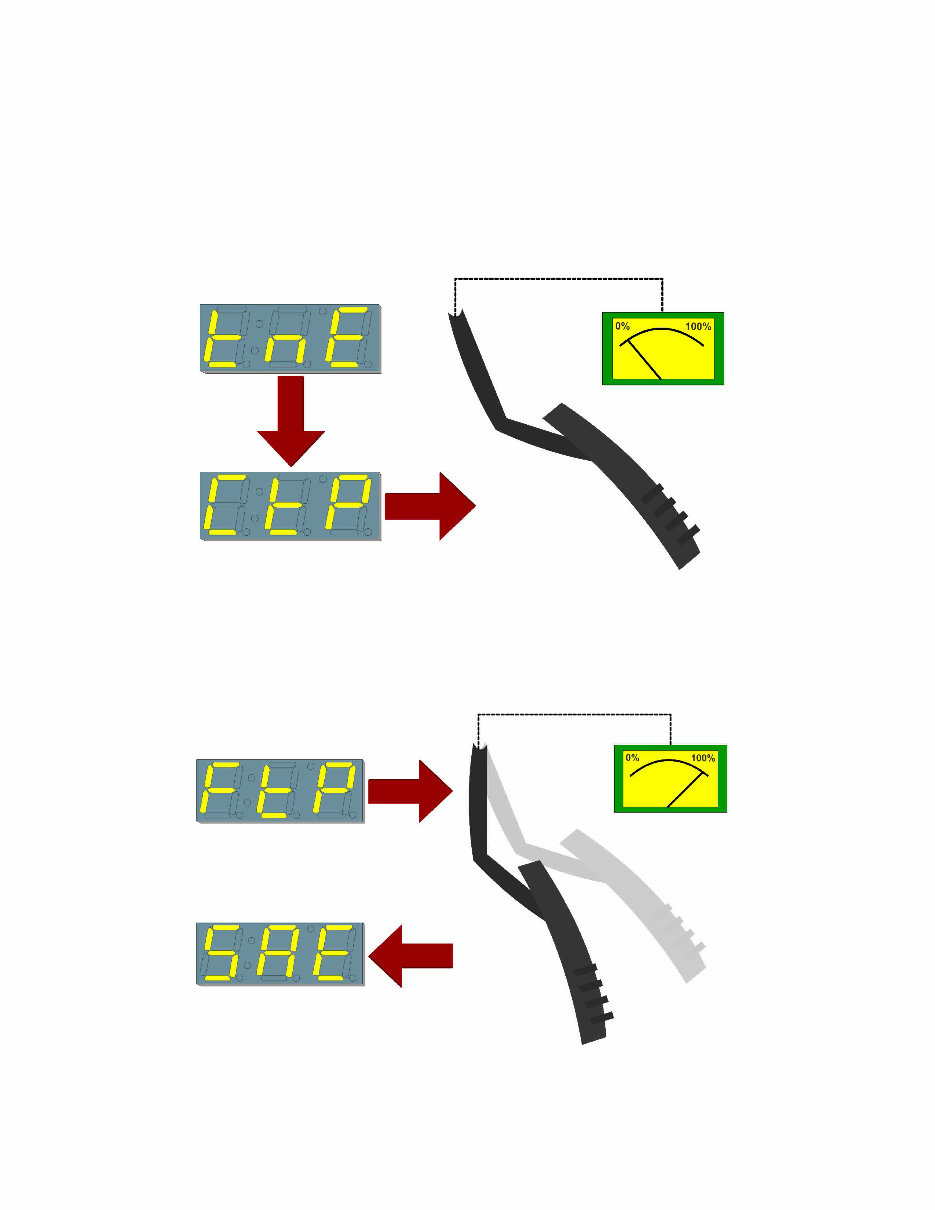
Step 7: Throttle Position Sensor Calibration
Set the Closed Throttle and Full Throttle Positions. This step should be done
with the ignition turned to “ON”, but the engine off. The engine should also be
warm.
Turn the knob to “Tune” (tnE) and click once. “Closed Throttle Position” (CtP)
should be displayed. Leave the accelerator untouched. Click the knob once,
then double-click to set the current Closed Throttle Position. Click again to exit.
Turn the knob to “Full Throttle Position” (FtP). Hold the accelerator all the way
down. Click the knob once, then double-click to set the current Full Throttle
Position. Click again to exit.
Turn the knob to “Save and Exit” (SAE). Click once to save and exit.
9

NOTES ON INSTALLATION
General Installation:
The Quick 1 unit should be mounted within the passenger compartment of the
vehicle in a protected location. Good mounting areas include under the dash,
behind a kick panel, or under the seat, as long as the unit and wiring are not
subject to damage. Under-hood mounting is NOT possible with the Quick 1 unit.
It is not waterproof or rated for under-hood temperatures. Passenger
compartment mounting is also necessary to provide easy access to the USB
port, which is used to interface with a PC for programming and diagnostics, as
well as the display and function control knob. For this reason, be sure to mount
the unit in a way that gives easy access to the USB port. If you will be using a
desktop PC for programming, install the unit so that it can be unplugged and
moved easily.
All electrical connections should be made using 60/40 rosin core solder. Cover
the connection with heat-shrinkable tubing for improved insulation and
mechanical strength. Individual connector terminals can be connected using a
“piggy-back” method, where the terminal is removed from the plastic connector
housing to allow the new wire to be soldered on to the terminal atop the original
wire. Two wires may be connected together by twisting them together
longitudinally, soldering, then covering with the appropriate size heat-shrink
tubing.
Before Driving the Vehicle:
Start the engine and move the shifter through all positions, ensuring that the
gear position and all sensor readings shown on the controller are correct. Most
importantly, make sure that no error codes are shown on the Quick 1 display. It
is a good idea to periodically check the Quick 1 display for errors as you drive,
so it is wise to consider an accessible mounting location. If any error codes or
unexpected characters are displayed, please refer to the user interface manual
for detailed explanations. If possible, perform a line pressure check to ensure
that line pressure is correct at idle (typically 60 - 80PSI), and that it smoothly
increases toward maximum (typically 190-240PSI) as the throttle position
increases. If you have any questions about the installation or line pressure
readings, please contact our technical support department.
10
You're Reading a Preview
What's Included?
Fast Download Speeds
Offline Viewing
Access Contents & Bookmarks
Full Search Facility
Print one or all pages of your manual
$52.99
Viewed 86 Times Today


Secure transaction
What's Included?
Fast Download Speeds
Offline Viewing
Access Contents & Bookmarks
Full Search Facility
Print one or all pages of your manual
$52.99
This comprehensive workshop manual is an essential resource for both professional mechanics and DIY enthusiasts. It provides detailed service and repair information specifically for the Chevrolet 4L60/4L60E transmission, combining a complete transmission service guide with an extensive parts catalog. Designed to support both overhaul and targeted repairs, this manual includes:
- Detailed rebuild procedures and repair instructions
- A comprehensive technician's guide featuring troubleshooting tips
- Step-by-step service and diagnostic information
- A complete parts catalog for accurate component identification
- Installation and operation instructions
- Comprehensive wiring and harness details
- Additional technical notes for precision repairs
Whether you are performing a complete transmission overhaul or addressing specific issues, this manual provides the clear guidance needed to ensure your repair job is done correctly and efficiently.


