

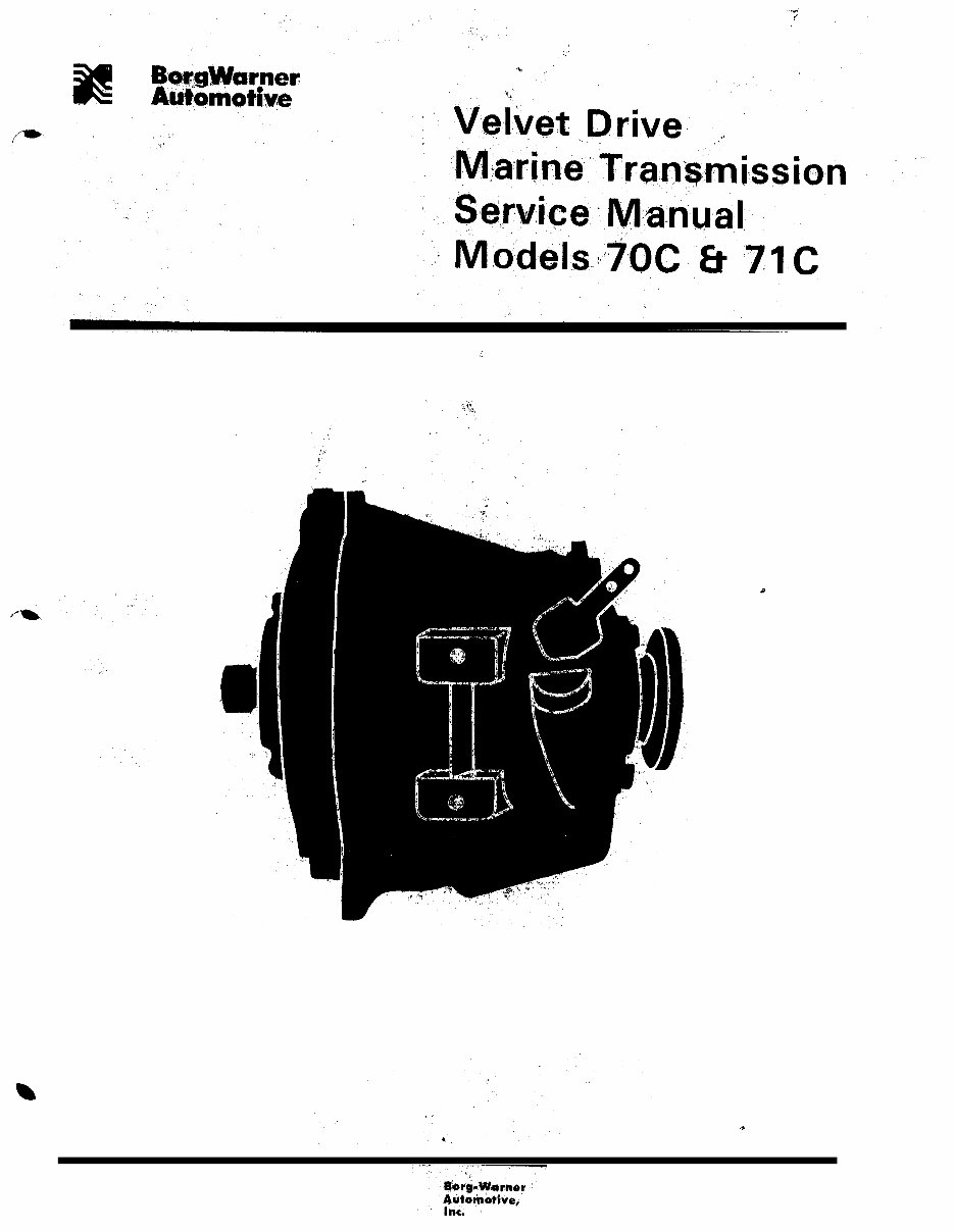
BORG WARNER VELVET DRIVE 70C 71C 72C 73C Gearbox Manual
What's Included?
Fast Download Speeds
Offline Viewing
Access Contents & Bookmarks
Full Search Facility
Print one or all pages of your manual
B!
lBokLgMhrner.
Automotive
,:
Transmission
Systems
SERVICE MANUAL
Price $5.00
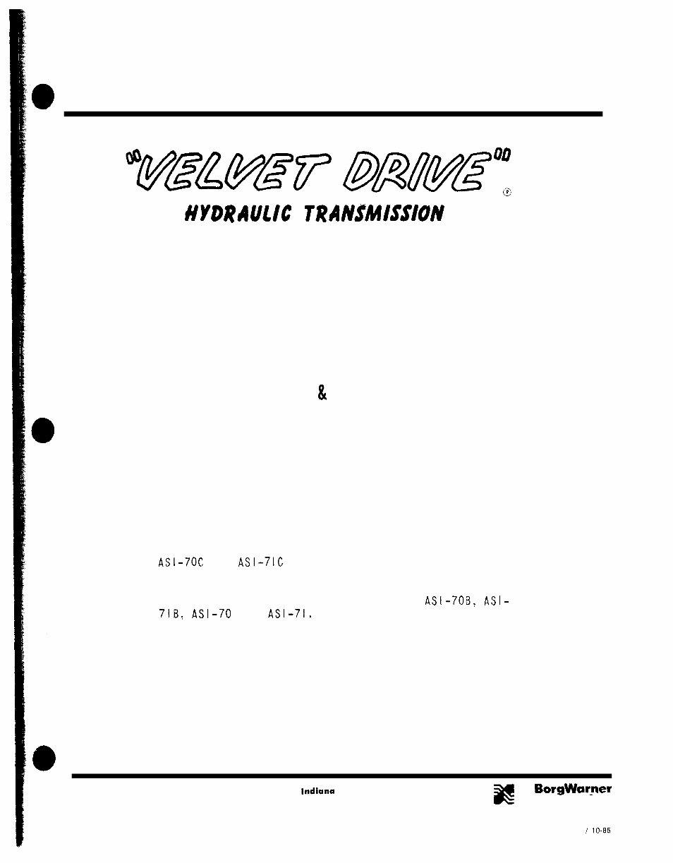
UYVR~ltlIC TRAN&WSION
DIRECT DRIVE
MODEL 70C & 71C SERIES
This Service Manual is prepared and illustrated for the
ASI-70C and ASI-7lC direct drive transmission, but it
also contains supplementary information and illustra-
tions which allow it to be used for the servicing of
the other earlier model transmissions, ASI-7OF.3, ASI-
7lB, ASI- and ASI-71.
Borg-Warner
Transmission 5401 Muncie Telephone
Automotive, Systems Kilqore lndiana 317 2866100 BorgWarner
Inc.
Avenue 47304 Telex
Automotive
27 491
FORM 1137 / lo-85
PRINTED IN U.S A
TABLE OF CONTENTS
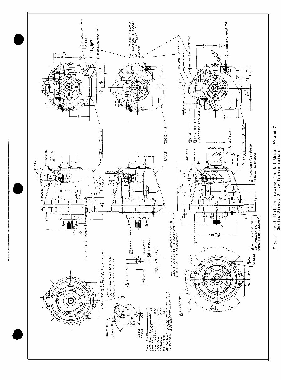
INSTALLATION DRAWINGS AND INFORMATION ........................................
.5
CROSS SECTlON ASSEMBLY DRAWlNGS ..............................................
.fi
EXPLODED VIEWS AND PARTS LISTS ................................................
I2
ClRCULATION DIAGRAM .........................................................
I9
DESCRIPTION..................................................................2 0
lNSTALLATIONPRECAUTIONS.....................................................2 I
Transmission oil cooler ..........................................................
.2 1
Control lever position...........................................................
.2l
Front pump mounting ..........................................................
,2 l
LUBRICATION RECOMMENDATlONS .................................................
21
Checking oil level ................................
1 .............................
.2 I
Changing oil
.................................................................
.2 1
Transmission fluid .............................................................
.2 1
Oilcapacity..................................................................7 1
TIiANSMISSIONOPERATlON.......................................................2 2
Forward .................................................................
...2 2
Ncutr:~l.....................................................................~ 2
Revcrsc.....................................................................2
.
Frecwhceling .................................................................
2~
Oilpressures..................................................................2 2
DISASSEMBLY OF TRANSMISSION. .................................................
.24
Oil draining procedure ..........................................................
.24
Disassembly ofvalvc and spring asscrnhly from transmission ..................................
24
Removal of front pump assembly ...................................................
.24
Removal of adapter and reverse clutch piston ............................................
35
Removal of thrust washer, reverse clutch pressure plate, pressure plate springs and dowel pins
........... .75
Removal of drive gear and clutch assembly .............................................
.25
Dissssen~hly of forward cluicl~ .....................................................
.2S
Removal of pinion cage and output shaft assembly from transmihon case ........................ .25
Removal of rear bearing .........................................................
.26
REASSEMBLYPRECAUTIONS.. ..................................................
..2 6
INSPECTION AND GENERAL INSTRUCTIONS..........................................
.27
ASSEMBLYOFTRANSMlSSlON ...................................................
..2 7
Assembling oil seal in bearing retainer ................................................ .27
Installation of baffle in the transmission case ............................................ .28
Installation of pinion cage and output shaft assembly in the transmission case...................... .28
Assembly of the forward clutch into tl~c ring gear ........................................ .3 I
Asscmhly of forward clutch huh and sealing rings on drive gears. ..............................
.34
Assemhlillg drive gear and clutch assembly .............................................
.35
Instnllation of drive gear and clutch assembly. reverse clutch plate, and reverse clutch prcssurc plate in
transInissiot~ case ............................................................
.30
Assembly of I-everse clutch piston into adapter ........................................... 3X
Asscml~ly of adapter and I-CV~I-SC clutch piston onto transmission cast ............................
3’)
Assembly of front pump.........................................................
.40
Mounting front pump or1 transmission ................................................ .41
Assembling valve spring assembly ...................................................
.4’3
Installation of the valve and spring assembly in the transmission’casc.
........................... .43
Assembly of shili lever ..........................................................
.44
Installation of oil strainer assembly and oil drain plug into transmission case.
...................... .45
Installation of miscellaneous transmission parts.......................................... .45
EXTRAEQUIPMENT..............,.....,........................................46
Assembly of neutral switch kit. . . . . . . . . . . . .46
SPECIAL INFORMATION AND INSTRUCTIONS -MODEL 70C AND 7 IC TRANSMISSIONS. . . .47
Installation of oil filler cap and dipstick assembly . . . . . . . . . . . . .47
Installation of oil strainer assembly and oil drain plug into transmission case. .47
Installation of breather assembly . . . . . . . . . . . . . . . . . . . .48
Assembly of front pump. . . . . . . . . . . . . . . . . . . . . . . . . . . . . . . .48
Mounting front pump on transmissiori. . / ,. . . SO
Elimination of regulator valve buzz. . . . . . . . . . . . . . . .5 I
Drive gear and plug assemblies . . . . . . . . . . .52
Pinion cage and output shaft assembly. . . . . . . . . . . . . . . . . . .52
Forward and reverse gear transmission case and bushing assembly. . . . . . . . .52
SPECIAL INFORMATION AND INSTRUCTIONS - MODEL 70B AND 7 1B TRANSMISSIONS .53
Instailation of breather assembly . . . . . . . . . . . . . . . . .53
Assembly of front pump. . . . . . . . . . . . . . . . . . . .5?
Drive gear and plug assembly. . . . . . .53
Assembly of shift lever. . . . . . . . . . . . . . .53
Adapter capscrews. . . . . .54
SPECIAL INFORMATION AND 1NSTRUCTIONS - MODEL 70 AND 71 TRANSMISSIONS . . .S4
Assembly of front pump. . . . . . . . . . . . . . . . . . . .54
Installation of the baffle in the transmission case, .S4
Installation of oil strainer assembly and oil drain plug into transmission case. .55
Cooler return to transmission. . . . . . . . .S5
SERVICE INSTRUCTIONS FOR SERIES lo-17 AND lo-18 TRANSMISSIONS ..56
TKOUBLE SHOOTING Cl IART . . , . . .58
BOLT TORQUE SPEClFlCATlONS. 1.1. . . . . .60
ASSEMBLY TOOL DRAWINGS . . . . .6 1
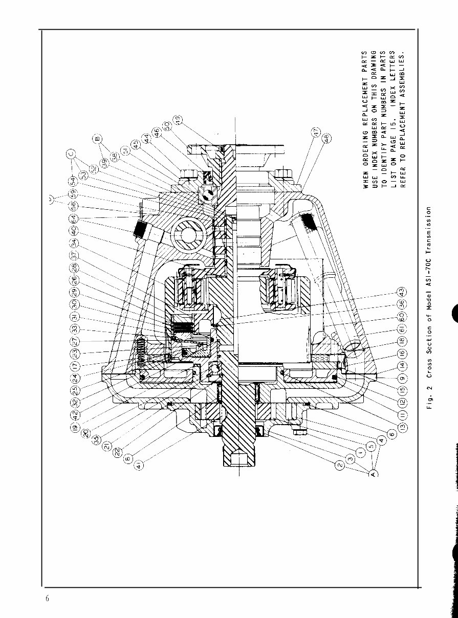
6
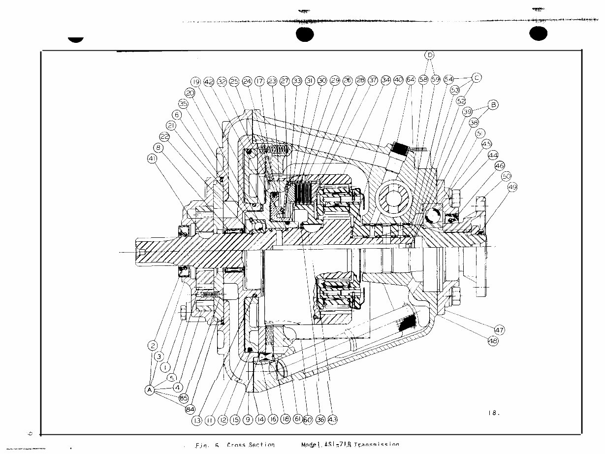
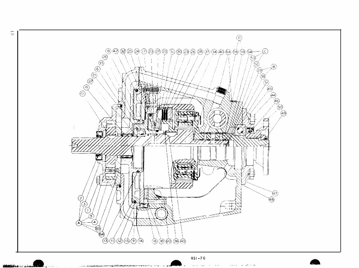
WHEN REPLACEMENT PARTS
USE INDEX NUMBERS ON THIS DRAWING
TO IDENTIFY PART NUMBERS IN PARTS
LIST ON PAGE 17. INDEX LETTERS
REFER TO REPLACEMENT ASSEMBLIES.
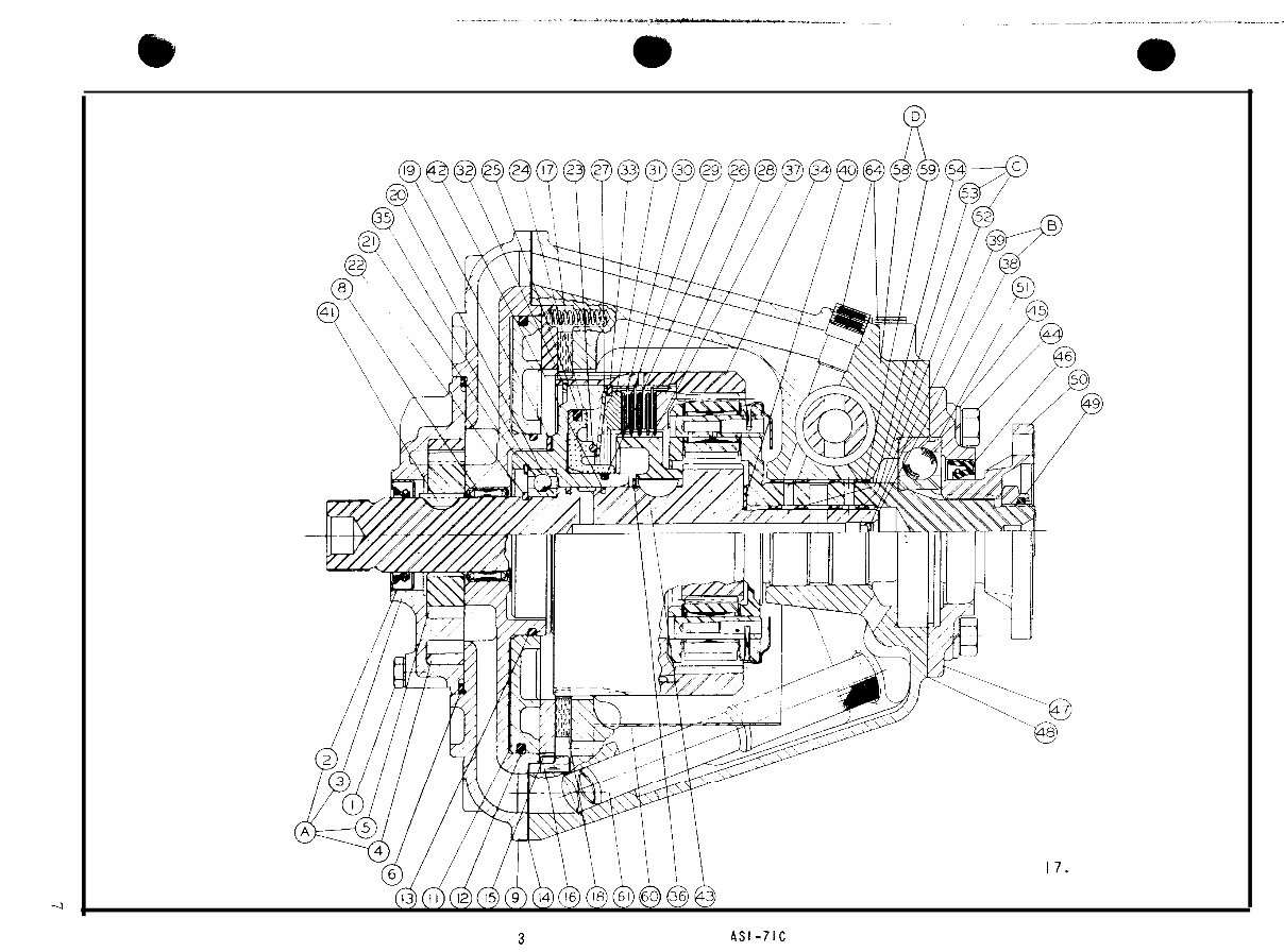
Fig. 3 Cross Section of Model ASI-7lC Transmission
WHEN ORDERING REPLACEMENT PARTS
USE INDEX NUMBERS ON THIS DRAWING
TO IDENTIFY PART NUMBERS IN PARTS
LIST ON PAGE 18. INDEX LETTERS
REFER TO REPLACEMENT ASSEMBLIES.
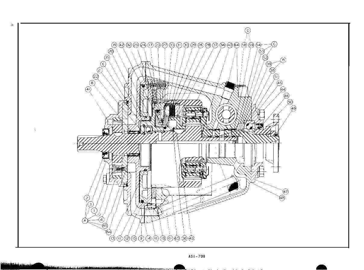
Fig. 4 Cross Section of Model ASI-70B Transmission
).-;I:
WHEN ORDERING REPLACEMENT PARTS
USE INDEX NUMBERS ON THIS DRAWING
TO IDENTIFY PART NUMBERS IN PARTS
LIST ON PAGE 18. INDEX LETTERS
60 36 3
REFER TO REPLACEMENT ASSEMBLIES.
.FFin. G urns ..Sectioq p f M,n&1,,ASl~7l& Tylnsmissinn
,
WHEN ORDERING REPLACEMENT PARTS
USE INDEX NUMBERS ON TH!S DRAWING
TO IDENTIFY PART NUMBERS IN PARTS
LIST ON PAGE 18.
INDEX LETTERS
REFER TO REPLACEMENT ASSEMBLIES.
Fig. 6 Cross Section of Model ASI- Transmission
You're Reading a Preview
What's Included?
Fast Download Speeds
Offline Viewing
Access Contents & Bookmarks
Full Search Facility
Print one or all pages of your manual
$39.99
Viewed 79 Times Today


Secure transaction
What's Included?
Fast Download Speeds
Offline Viewing
Access Contents & Bookmarks
Full Search Facility
Print one or all pages of your manual
$39.99
This workshop service manual is for the Borg Warner Velvet Drive 70C, 71C, 72C, 73C transmissions, and it includes the owner's manual. It contains:
- Information & installation drawings
- Cross-section assembly drawings
- Parts display & information
- Circulation diagram
- Installation precaution
- Lubrication recommendation
- Transmission operation
- Disassembly of transmission
- Reassembly precaution
- Inspection & instruction
- Assembly of transmission
- Extra equipment
- Special information
- Special service kits
- Troubleshooting chart
- Torque specification
This comprehensive workshop manual is in scanned format and is utilized by service technicians for accurate service and maintenance on Borg Warner transmissions. It provides detailed step-by-step procedures with pictures and diagrams, and is fully printable. This manual is ideal for repairs, maintenance, and servicing, and is suitable for both professional mechanics and DIY enthusiasts.


