


2
Electronic Transmission Control
Table of Contents
Subject Page
Adaptive Features ................................................................................ 38
Driver Influenced Features ..................................................................... 39
Environmentally Influenced Features ...................................................... 40
CAN Bus Communication ....................................................................42
Diagnosis and Troubleshooting ...........................................................46
Estblishing a Diagnostic Plan .................................................................47
Fault Codes ...........................................................................................48
Identification Page .................................................................................49
Diagnostic Program ...............................................................................50
Test Modules ..........................................................................................51
Diagnostic Tips ......................................................................................52
Information Resources ...........................................................................53
TCM Coding and Programming ...........................................................54
Transmission Fluid Information ...........................................................56
Transmission Fluid Checking Procedures ...............................................57
Transmission Fluid Application ...............................................................58
Transmission Service ............................................................................59
Transmission Tools ...............................................................................60
Review Questions .................................................................................66
Electronic Transmission Control
38
Electronic Transmission Control
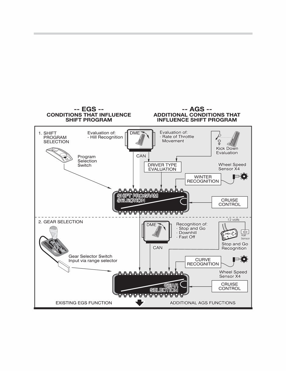
Adaptive Features (AGS)
AGS features were introduced in 1994 with the A5S560Z transmission. AGS control con-
sists of adaptive features that will modify transmission operation according to various fac-
tors. AGS operation can be influenced by two major functional groups:
• Driver influenced features (influenced by throttle and kickdown input)
• Environmental influences (such as road conditions - icy, traffic etc.)
The driving program selection is not adapted on a long term basis - nor is it stored
in the control module memory when the ignition is switched off. It continually
changes as the driver of the vehicle changes driving habits.
39
Electronic Transmission Control
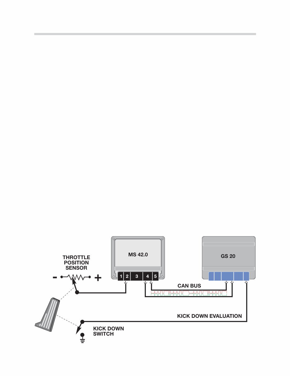
Driver influenced features of AGS
The adaptive drive program is based primarily on throttle input. The throttle information
comes from the ECM (DME) via the CAN bus. The TCM continuously monitors the throttle
input for:
• The current throttle position
• The rate of change in pedal movement
• The number of acceleration requests
• The number of kickdown requests
Drive away Evaluation
The AGS system selects the appropriate shift program based on the amount of accelera-
tion that occurs during takeoff. When driving away under full throttle the transmission will
shift from XE to E.
Kick Fast Feature
Based on these inputs, the AGS will select one three different driving programs as follows:
• Extreme Economy - Shift points are a low speeds for maximum comfort and economy
• Economy - The shift points are raised for more performance with economy as priority
• Sport - The shift points are higher to take advantage of full engine performance.
Under full throttle acceleration at high speed, single gear downshifts are possible. A two
gear downshift is possible if the accelerator pedal is moved quickly to kick-down. The
Extreme Sport program was eliminated as part of the kick-fast feature.
40
Electronic Transmission Control
Environmentally influenced AGS features
STOP and GO
The feature is activated by defined sequence of shifts which are as follows:
• Upshift from first to second - followed by a downshift from second to first - followed
by another upshift from first to second. This is then followed by the vehicle coming
to a complete stop.
After this sequence occurs, the transmission will stay in second gear. The AGS control has
recognized stop and go driving and this function will prevent excessive shifting during heavy
conditions. The second gear start will be cancelled when:
• The vehicle speed exceeds 40 MPH
• The throttle pedal is pressed more than 90%
• The range selector is moved to Park, Neutral, Reverse or Sport (4,3 or 2)
• The vehicle is in Sport Mode
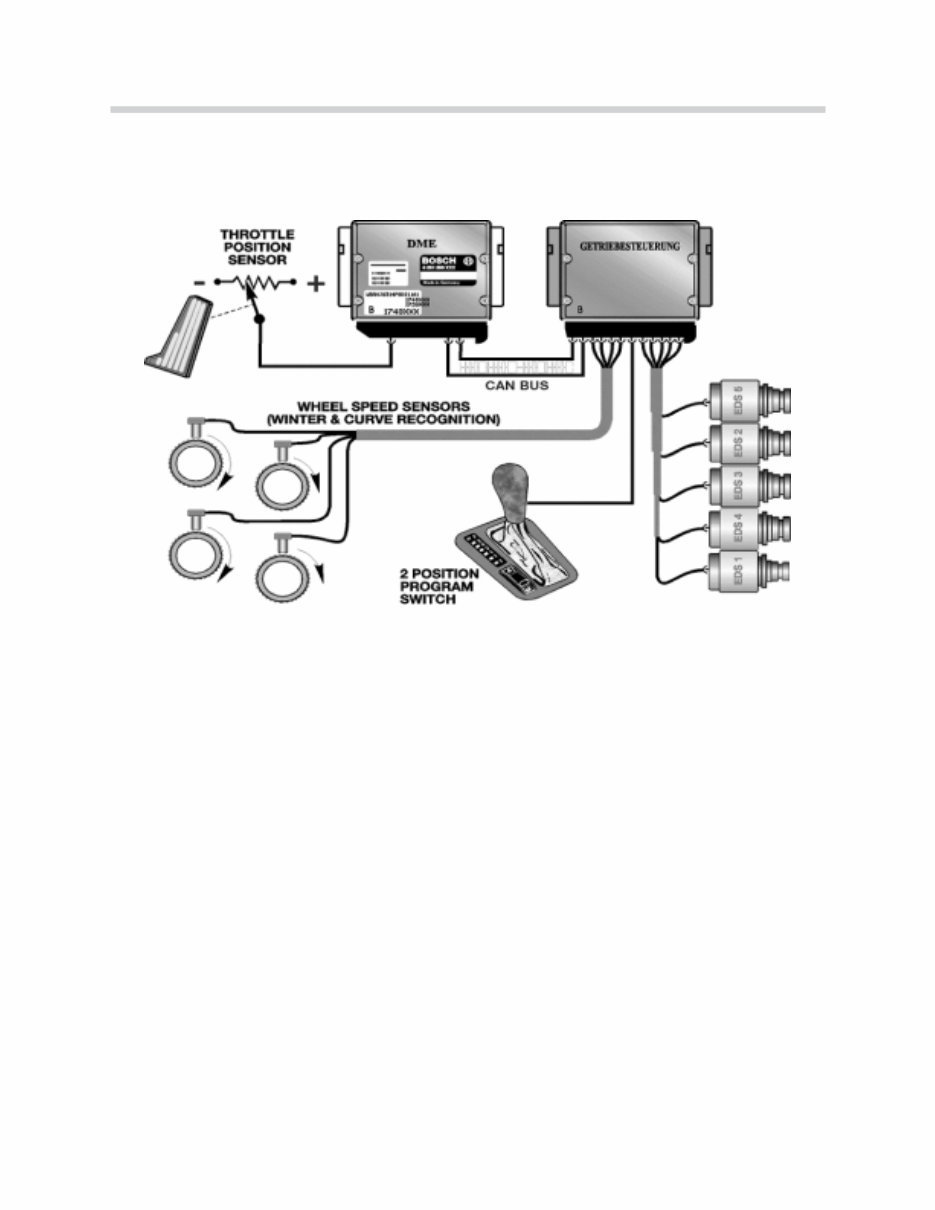
Winter Drive Program
This feature is activated when the TCM detects slippage at the rear wheels by comparing
front and rear wheel speed signals. When slippage is detected by the TCM, the transmis-
sion will start in second gear and the shift points will be lowered. This will reduce torque to
the rear wheels allowing improved driveability and traction on slippery roads.

41
Electronic Transmission Control
Hill Recognition Program
There are two hill recognition programs, one for Uphill and one for Downhill. The TCM will
activate this feature when it receives a high engine load signal at slower road speeds. The
TCM will perceive this information as being consistent with climbing a hill. The shift points
will be raised to prevent constant up and down shifting. This is referred to as the pendulum
shift effect. When driving downhill, road speed will increase with minimal throttle input. The
TCM will detect a downhill situation and hold the current gear to prevent an upshift when
going downhill.
Curve Recognition
This feature will inhibit upshifts when the vehicle is in a curve. This is to improve stability
when the vehicle is cornering at high speeds. The TCM will initiate this feature when it
detects a difference between left and right (front) wheel speed signals. The difference in
these signals will indicate that the vehicle is in a curve. Be aware that improper tire sizes,
brands and inflation pressures can influence this feature. Always address these issues first
when diagnosing delayed upshift complaints.
Cruise Control Drive program
A special cruise control shift map is selected by the TCM when cruise control is active. The
TCM will prevent unwanted locking and unlocking of the torque converter clutch. Also,
upshifting and downshifting will be minimized. Depending upon application, the cruise con-
trol interfaces with TCM via a single wire data link or as on vehicles with electronic throttle
control, the TCM will interface with the ECM (DME).
Manually Selected “Extreme Sport” Program
This feature is activated by moving the shift lever to position 4, 3 or 2. This activates the
“Extreme Sport Program” where the shift points are raised for maximum rpm and perfor-
mance. On Steptronic equipped vehicles, the sport program is obtained by moving the
shifter to the manual gate to initiate the “Sport Program”.
Modifications to AGS features
Since the introduction of AGS features in 1994, there have been some software changes
to address customer concerns. Some AGS features have been perceived by the customer
as malfunctions. To correct this, some of the AGS features were modified with updated
software. The AGS features previously discussed in this text reflect the updated modifica-
tions. Always refer to the latest Service Information Bulletins for more information on AGS
features.
42
Electronic Transmission Control
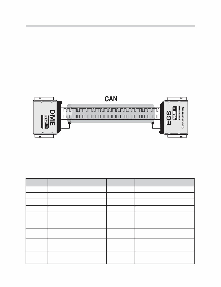
CAN Bus Communication
The CAN bus is a serial communications bus in which all connected control units can send
as well as receive information. Data over the CAN bus operates at a rate of up to 1Mb/s
(megabits per second).
The CAN protocol was developed by Intel and Bosch in 1988 for use in the automotive
industry to provide a standardized, reliable and cost-effective communications bus to com-
bat the increasing size of wiring harnesses.
The CAN bus was originally introduced on BMW automobiles in the 1993 E32 740i/IL as a
data link between the TCM (EGS) and the ECM (DME).
On earlier EGS systems, various signals were transmitted on individual signal wires. This
reduced reliability and increased the amount of wiring needed. The CAN bus allows faster
signal transmission and increased versatility. For example, the signals listed in the chart
below were previously transmitted on individual wires, now these signals are all on the CAN
bus. This chart represents only some of the signals on the CAN bus, there are many more
signals transmitted between the TCM and ECM.
Sender Information Item Receiver Signal Use
ECM Engine Temperature TCM Shift Point Calculation
ECM Engine Load (tL) TCM Shift Point Calculation
ECM Engine RPM (TD) TCM TCC Slippage
ECM Throttle Position (DKV) TCM Shift Point Calculation
ECM A/C Compressor ON TCM Fine tune shift points to compensate
for increased engine load.
TCM Transmission Range ECM Engine Idle Speed Control
TCM Torque Reduction Signal (ME) ECM Timing Retard during shifts.
TCM TCC Lockup Status ECM Engine Timing Map adjustment.
Bi-Directional Data
43
Electronic Transmission Control
CAN Bus Topology
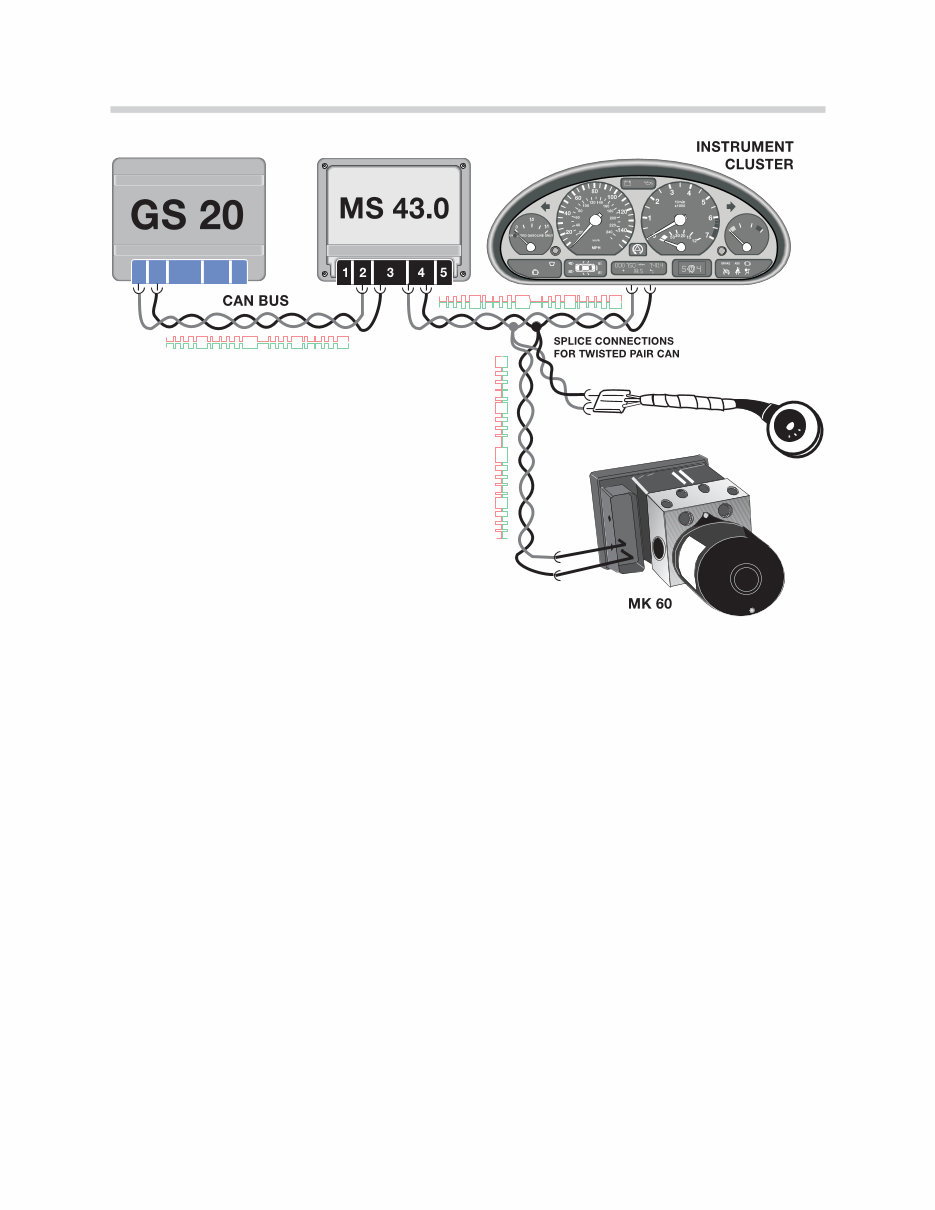
The CAN bus consists of two twisted copper wires. Each wire contains an opposing sig-
nal with the exact same information (CAN-High, CAN-Low). The opposing signals trans-
mitted through the twisted wire serve to suppress any electrical interference. Early CAN
bus wiring included a grounded shield around the two wires, later vehicles discarded the
shield in favor of the unshielded twisted pair wiring.
Due to the linear structure of the network, the CAN bus is available for other modules in the
event of a disconnected or failed control unit. This is referred to as a “Tree” structure with
each control unit occupying a branch.
As previously mentioned, the CAN bus initially was used as a high speed communication
link between the DME and AGS control units.
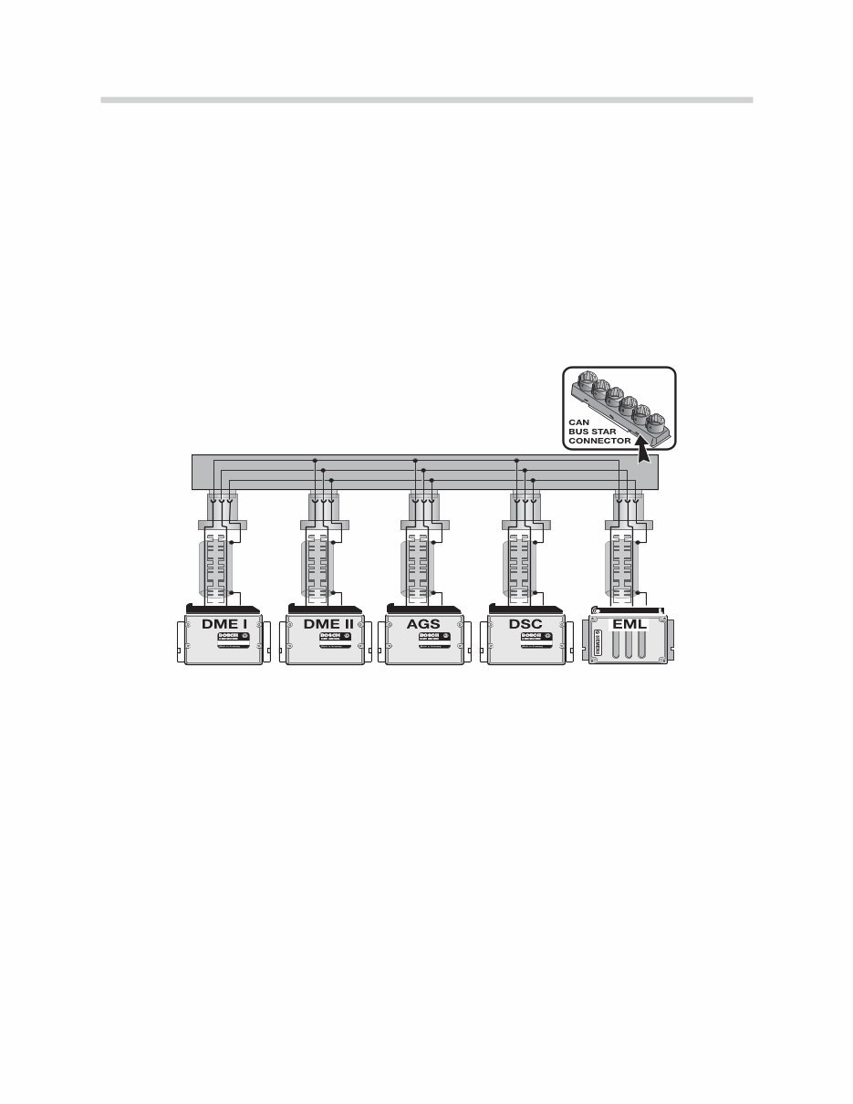
With the introduction of the E38 750iL (95 M.Y.), the CAN bus was expanded to include the
EML and DSC control modules. The 750iL made exclusive use of the “star coupler” to link
the individual CAN bus ends to a common connector.
The 1998 model year introduced new users of the CAN bus. The instrument cluster and
the steering angle sensor were linked to expand the signal sharing capabilities of the vehi-
cle.
The 1999 750iL was the last vehicle to use the shielded cable, after which the entire CAN
bus went to twisted pair wiring.
Note: Always refer to the proper ETM to determine the exact wiring configuration
for a specific model.
44
Electronic Transmission Control
On models that use twisted pair, the wire color of the CAN bus is uniform throughout the
vehicle with: CAN-Low GE/BR and CAN-High GE/SW or GE/RT. Shielded wiring is easily
identified by the black sheath surrounding the CAN bus.
Troubleshooting the CAN Bus
The failure of communication on the CAN bus can be caused by several sources:
• Failure of the CAN bus cables.
• Failure of one of the control units attached to the CAN.
• Failure of the voltage supply or ground to individual modules.
• Interference in the CAN bus cables.
Failure of the CAN bus cables
The following faults can occur to the CAN bus wiring:
• CAN-H/L interrupted
• CAN-H/L shorted to battery voltage
• CAN-H/L shorted to ground
• CAN-H shorted to CAN-L
• Defective plug connections (damaged, corroded, or improperly crimped)
In each instance, the connected control units will store a fault due to the lack of information
received over the CAN bus.
On most current models the CAN bus pro-
vides data exchange between the following
control modules:
• ECM (DME)
• EML (750iL E38)
• TCM (EGS)
• IKE/Kombi
• ASC/DSC
• LEW
45
Electronic Transmission Control
The voltage of the CAN bus is divided
between the two data lines: CAN-High
and CAN-Low for an average of 2.5V per
line. The voltage measurement is taken
from each data line to ground. Each mod-
ule on the CAN contributes to this voltage.
The fact that 2.5V are present does not
mean that the CAN bus is fault free, it just
means that the voltage level is sufficient to
support communication.
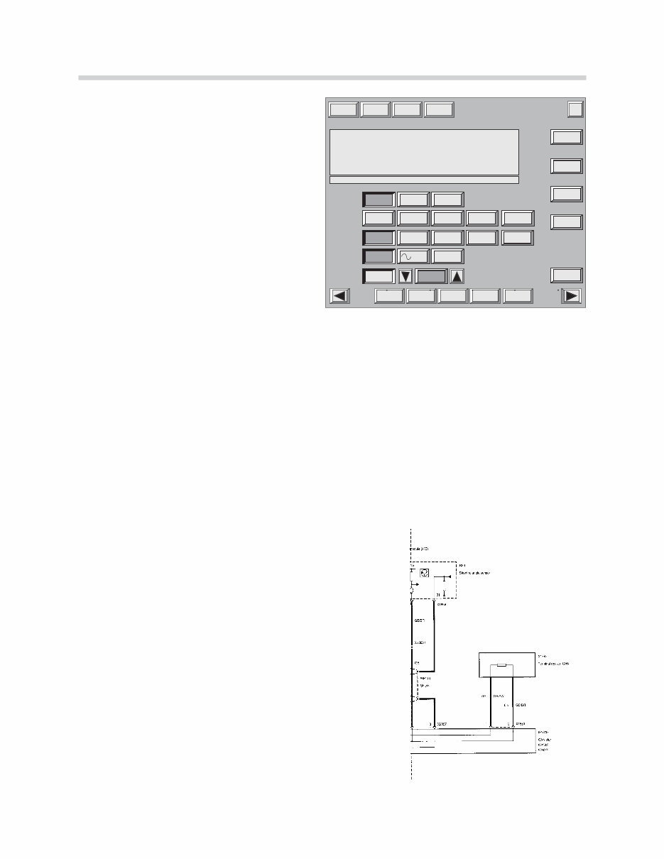
Terminal Resistors: are used in the CAN bus circuit to establish the correct impedance
to ensure fault free communication. A 120 Ohm resistor is installed in two control units of
the CAN between CAN-H and CAN-L. Because the CAN is a parallel circuit, the effective
resistance of the complete circuit is 60 Ohms. On some vehicles there is a jumper wire that
connects the two parallel branches together, others have an internal connection at the
instrument cluster.
The resistance is measured by connecting the appropriate adapter to any of the modules
on the CAN and measuring the resistance between CAN-L and CAN-H. The resistance
should be 60 Ohms. The CAN bus is very stable and can continue to communicate if the
resistance on the CAN bus is not completely correct; however, sporadic communication
faults will occur.
The terminal resistors are located in the ASC/DSC
control unit and either the instrument cluster or in the
DME.
Early 750iL vehicles that used the star connector have
a separate external resistor which connect CAN-H
and CAN-L together.
Modules which do not have the terminal resistor can
be checked by disconnecting the module and check-
ing the resistance directly between the pins for CAN-
H and CAN-L. The value at these control units should
be between 10kOhms and 50kOhms.
Print
Multimeter
End
Oscilloscope
setting
Change
Counter
Services Help
Stimulators Preset
measurements
BMW Test system Multimeter
Measurement
Function
Measurement
Connection
Measurement
Kind
Measurement
Range
10 0 10
Resistance Resistance
Ohm Ohm
Temperature
C
o
Temperature
C
o
Voltage Voltage
V V
Current Current
MFK 1 MFK 1 MFK 2 MFK 2
Current Current Current Current Diode test Diode test Pressure Pressure
2A 2A 50A 50A 1000A 1000A bar bar -|>|- -|>|-
Current probe Current probe Pressure
Sensor
Pressure
Sensor
Temperature
Sensor
Temperature
Sensor
Freeze image Freeze image
2nd
measurement
2nd
measurement
System voltage
Rotation speed
System voltage
Rotation speed
Stimulate Stimulate
Minimum
Maximum
Minimum
Maximum
=
Effective value Effective value
automatic automatic ± 10 V ± 10 V
2.35 V 2.65 V

46
Electronic Transmission Control
Diagnosis and Troubleshooting
Due to the cost and complexity of today's electronic transmissions, BMW recommends
that the technical hotline be contacted before any repairs are performed. It is important that
the technician perform some basic diagnostic procedures before contacting technical
assistance. The following procedures should be followed:
• Always Verify customer complaint, make sure the complaint is not related to normal
operation. (i.e. Warm Up Phase, AGS operation etc.)
• Survey Fault Memory - Perform complete quick test. There may be other systems that
interface with EGS that could cause faults. (i.e DME, ASC/DSC, IKE/Kombi etc.)
• Print out all fault code with fault conditions. Also print out copy of Identification page and
diagnostic report.
• CHECK TO SEE IF THERE ARE ANY SERVICE BULLETINS THAT APPLY TO YOUR
SPECIFIC COMPLAINT. THIS INCLUDES THE SERVICE ROUNDTABLE.
• Ensure that battery voltage is sufficient. Battery voltage must be greater than 12.5 with
ignition switched off. Check battery connections for tightness and condition.
• Check ground connections. (chassis to engine, grounds to bulkhead and shock tower.)
• Check over vehicle to look for transmission leaks, physical damage, loose connections
etc.
• If necessary, check fluid level and condition using DISplus or GT-1.
• Check to see if any aftermarket or performance components have been installed that
could effect transmission operation. (DME or EGS software as well as any engine mod-
ifications).
• Check repair history to see if there were any recent repairs that could effect the proper
operation of the transmission (i.e. Engine replacement with damaged dowel pin etc.).
• Check DCS for any open campaigns or recalls pertaining to drivetrain.
• Check and record chassis number, production date and transmission serial # before
contacting technical assistance.
You're Reading a Preview
What's Included?
Fast Download Speeds
Online & Offline Access
Access PDF Contents & Bookmarks
Full Search Facility
Print one or all pages of your manual
$31.99
BMW Automatic Transmission Gearbox Workshop Manual
Viewed 31 Times Today

What's Included?
Fast Download Speeds
Online & Offline Access
Access PDF Contents & Bookmarks
Full Search Facility
Print one or all pages of your manual
$31.99

Secure transaction
What's Included?
Fast Download Speeds
Online & Offline Access
Access PDF Contents & Bookmarks
Full Search Facility
Print one or all pages of your manual
Description
This repair manual provides comprehensive information for diagnosing and troubleshooting breakdowns of BMW automatic transmission. It covers the following key areas:
- Electronic Transmission Control
- - Adaptive Features
- - Driver Influenced Features
- - Environmentally Influenced Features
- - CAN Bus Communication
- Diagnosis and Troubleshooting
- - Establishing a Diagnostic Plan
- - Fault Codes
- - Identification Page
- - Diagnostic Program
- - Test Modules
- - Diagnostic Tips
- - Information Resources
- TCM Coding and Programming
- Transmission Fluid Information
- - Transmission Fluid Checking Procedures
- - Transmission Fluid Application
- Transmission Service
- Transmission Tools
- Review Questions
This manual is a valuable resource for both professional mechanics and DIY enthusiasts.


