TS2470EN
Printed in the U.S.A. Copyright © 1998 General Motors Corp.
Troubleshooting
Manual
Division of General Motors Corporation
P.O. Box 894 Indianapolis, Indiana 46206-0894
May 1998
Revision 1, 199910
Allison Transmission
MD/HD/B Series Transmissions
WTEC II Controls
(Pre-TransID and TID 1)
MD 3060/MD 3066/MD 3560(P)(R)
MD 3070PT
HD 4060/HD 4560(P)(R)
B 300/B 400/ B 500(P)(R)
WTEC II ELECTRONIC CONTROLS TROUBLESHOOTING MANUAL
ii Copyright © 1998 General Motors Corp.
This manual provides troubleshooting information for Allison Transmission Division, MD/HD/B Series
Transmissions. Service Manuals SM2148EN and SM2457EN, and Parts Catalogs PC2150EN and PC2456EN may
be used in conjunction with this manual.
This manual includes:
• Description of the WTEC II electronic control system.
• Description of the electronic control system components.
• Description of diagnostic codes, system responses to faults, and troubleshooting.
• Wire, terminal, and connector repair information.
Specific instructions for using many of the available or required service tools and equipment are not included in
this manual. The service tool manufacturer will furnish instructions for using the tools or equipment.
Additional information may be published from time to time in Service Information Letters (SIL) and will be
included in future revisions of this and other manuals. Please use these SILs to obtain up-to-date information
concerning Allison Transmission products.
This publication is revised periodically to include improvements, new models, special tools, and procedures. A
revision is indicated by a letter suffix added to the publication number. Check with your Allison Transmission
service outlet for the currently applicable publication. Additional copies of this publication may be purchased from
authorized Allison Transmission service outlets. Look in your telephone directory under the heading of
Transmissions — Truck, Tractor, etc.
Take time to review the Table of Contents and the manual. Reviewing the Table of Contents will aid you in quickly
locating information.
NOTE: Allison Transmission is providing for service of WTEC II wiring harnesses and wiring harness
components as follows: (See Service Information Letter 1-WT-97 for further information.)
• Repair parts for the internal wiring harness and for wiring harness components attached to the shift selector
will be available through the Allison Transmission Parts Distribution Center (PDC). Use the P/N from your
appropriate parts catalog or from Appendix E in this manual. Allison Transmission is responsible for
warranty on these parts.
• Since January, 1998, all WTEC II external harnesses and external harness components must be obtained
from St. Clair Technologies Inc. (SCTI). SCTI provides parts to any Allison customer or OEM and is
responsible for warranty on these parts. SCTI recognizes ATD, manufacturers, and SCTI part numbers.
SCTI provides a technical HELPLINE at 519-627-1673 (Wallaceburg). SCTI has parts catalogs available.
The SCTI addresses and phone numbers for parts outlets are:
St. Clair Technologies, Inc.
1050 Old Glass Road
Wallaceburg, Ontario, Canada, N8A 3T2
Phone: (519) 627-1673
Fax: (519) 627-4227
St. Clair Technologies, Inc.
1111 Mikesell Street
Charlotte, Michigan 48813
Phone: (517) 541-8166
Fax: (517) 541-8167
St. Clair Technologies, Inc.
c/o Mequilas Tetakawi
Carr. Internationale KM 1969
Guadalajara – Nogales, KM2
Empalme, Sonora, Mexico
Phone: 011-52-622-34661
Fax: 011-52-622-34662
FOREWORD — How to Use This Manual
Copyright © 1998 General Motors Corp. iii
WTEC III ELECTRONIC CONTROLS TROUBLESHOOTING MANUAL
IMPORTANT SAFETY NOTICE
IT IS YOUR RESPONSIBILITY to be completely familiar with the warnings and cautions
used in this manual. These warnings and cautions advise against using specific service
procedures that can result in personal injury, equipment damage, or cause the equipment to
become unsafe. These warnings and cautions are not exhaustive. Allison Transmission could
not possibly know, evaluate, or advise the service trade of all conceivable procedures by which
service might be performed or of the possible hazardous consequences of each procedure.
Consequently, Allison Transmission has not undertaken any such broad evaluation.
Accordingly, ANYONE WHO USES A SERVICE PROCEDURE OR TOOL WHICH IS NOT
RECOMMENDED BY ALLISON TRANSMISSION MUST first be thoroughly satisfied
that neither personal safety nor equipment safety will be jeopardized by the service proce-
dures used.
Also, be sure to review and observe WARNINGS, CAUTIONS, and NOTES provided by the
vehicle manufacturer and/or body builder before servicing the Allison transmission in that
vehicle.
Proper service and repair is important to the safe and reliable operation of the equipment. The
service procedures recommended by Allison Transmission and described in this manual are
effective methods for performing troubleshooting operations. Some procedures require using
specially designed tools. Use special tools when and in the manner recommended.
WARNINGS, CAUTIONS, AND NOTES
Three types of headings are used in this manual to attract your attention:
NOTE: Is used when an operating procedure, practice, etc., is essential to highlight.
WARNING!
Is used when an operating procedure, practice, etc., which, if not correctly followed,
could result in injury or loss of life.
CAUTION:
Is used when an operating procedure, practice, etc., which, if not strictly observed, could
result in damage to or destruction of equipment.
The WARNINGS, CAUTIONS, and NOTES in this manual apply only to the Allison transmission
and not to other vehicle systems which may interact with the transmission. Be sure to review and
observe any vehicle system information provided by the vehicle manufacturer and/or body builder
at all times the Allison transmission is being serviced.
WTEC II ELECTRONIC CONTROLS TROUBLESHOOTING MANUAL
iv Copyright © 1998 General Motors Corp.
TRADEMARKS USED IN THIS MANUAL
The following trademarks are the property of the companies indicated:
• LPS
®
Cleaner is a registered trademark of LPS Laboratories.
• VCI #10
®
is the registered trademark for a vapor phase rust preventive manufactured by Daubert Chemical
Company, Chicago, Illinois. VCI #10 is covered by Military Specifications MIL-L-46002 (ORD) and
MIL-I-23310 (WEP) under the designation of Nucle Oil.
• Biobor JF
®
is the registered trademark for a biological inhibitor manufactured by Hammonds Fuel Additives
Corporation.
• Loctite
®
is a registered trademark of the Loctite Corporation.
• Teflon
®
is a registered trademark of the DuPont Corporation.
• Pro-Link
®
is a registered trademark of MicroProcessor Systems, Inc.
SHIFT SELECTOR TERMS AND DISPLAY INDICATIONS
Shift selector terms and displays are represented in this manual as follows:
• Button Names — ⇑ ⇓ , DISPLAY MODE, MONITOR, SELECT, etc.
• Transmission Ranges — D (Drive), N (Neutral), 1 (First), R (Reverse), etc.
• Displays — “ OL ”, “ OK ”, etc.
Copyright © 1998 General Motors Corp. v
Page
Foreword . . . . . . . . . . . . . . . . . . . . . . . . . . . . . . . . . . . . . . . . . . . . . . . . . . . . . . . . . . . . . . . . . . . . . . . . . . i
SAFETY INFORMATION
Important Safety Notice . . . . . . . . . . . . . . . . . . . . . . . . . . . . . . . . . . . . . . . . . . . . . . . . . . . . . . . . . iii
Warnings, Cautions, and Notes . . . . . . . . . . . . . . . . . . . . . . . . . . . . . . . . . . . . . . . . . . . . . . . . . . . . iii
Trademarks Used in This Manual . . . . . . . . . . . . . . . . . . . . . . . . . . . . . . . . . . . . . . . . . . . . . . . . . . iv
Shift Selector Terms and Display Indications . . . . . . . . . . . . . . . . . . . . . . . . . . . . . . . . . . . . . . . . . iv
SECTION 1. GENERAL DESCRIPTION
1–1. TRANSMISSION . . . . . . . . . . . . . . . . . . . . . . . . . . . . . . . . . . . . . . . . . . . . . . . . . . . . . . . . . . . . . . 1–1
1–2. ELECTRONIC CONTROL UNIT (ECU) . . . . . . . . . . . . . . . . . . . . . . . . . . . . . . . . . . . . . . . . . . . 1–3
1–3. SHIFT SELECTOR . . . . . . . . . . . . . . . . . . . . . . . . . . . . . . . . . . . . . . . . . . . . . . . . . . . . . . . . . . . . 1–3
A. Pushbutton Shift Selector . . . . . . . . . . . . . . . . . . . . . . . . . . . . . . . . . . . . . . . . . . . . . . . . . . . . . 1–3
B. Lever Shift Selector . . . . . . . . . . . . . . . . . . . . . . . . . . . . . . . . . . . . . . . . . . . . . . . . . . . . . . . . . 1–4
1–4. THROTTLE POSITION SENSOR . . . . . . . . . . . . . . . . . . . . . . . . . . . . . . . . . . . . . . . . . . . . . . . . . 1–4
1–5. SPEED SENSORS . . . . . . . . . . . . . . . . . . . . . . . . . . . . . . . . . . . . . . . . . . . . . . . . . . . . . . . . . . . . . 1–5
1–6. CONTROL MODULE . . . . . . . . . . . . . . . . . . . . . . . . . . . . . . . . . . . . . . . . . . . . . . . . . . . . . . . . . . 1–6
1–7. WIRING HARNESSES . . . . . . . . . . . . . . . . . . . . . . . . . . . . . . . . . . . . . . . . . . . . . . . . . . . . . . . . . 1–7
A. External Wiring Harness . . . . . . . . . . . . . . . . . . . . . . . . . . . . . . . . . . . . . . . . . . . . . . . . . . . . . . 1–7
B. Internal Wiring Harness . . . . . . . . . . . . . . . . . . . . . . . . . . . . . . . . . . . . . . . . . . . . . . . . . . . . . . 1–8
1–8. VEHICLE INTERFACE MODULE . . . . . . . . . . . . . . . . . . . . . . . . . . . . . . . . . . . . . . . . . . . . . . . . 1–10
1-9. TRANSID FEATURE . . . . . . . . . . . . . . . . . . . . . . . . . . . . . . . . . . . . . . . . . . . . . . . . . . . . . . . . . . . 1-10
SECTION 2. DEFINITIONS AND ABBREVIATIONS
2–1. DO NOT SHIFT LIGHT . . . . . . . . . . . . . . . . . . . . . . . . . . . . . . . . . . . . . . . . . . . . . . . . . . . . . . . . . 2–1
2–2. DIAGNOSTIC DATA READER . . . . . . . . . . . . . . . . . . . . . . . . . . . . . . . . . . . . . . . . . . . . . . . . . . 2–1
2–3. ABBREVIATIONS . . . . . . . . . . . . . . . . . . . . . . . . . . . . . . . . . . . . . . . . . . . . . . . . . . . . . . . . . . . . . 2–2
SECTION 3. BASIC KNOWLEDGE
3–1. BASIC KNOWLEDGE REQUIRED . . . . . . . . . . . . . . . . . . . . . . . . . . . . . . . . . . . . . . . . . . . . . . . 3–1
3–2. USING THE TROUBLESHOOTING MANUAL . . . . . . . . . . . . . . . . . . . . . . . . . . . . . . . . . . . . . 3–1
3–3. SYSTEM OVERVIEW . . . . . . . . . . . . . . . . . . . . . . . . . . . . . . . . . . . . . . . . . . . . . . . . . . . . . . . . . . 3–2
3–4. IMPORTANT INFORMATION IN THE TROUBLESHOOTING PROCESS . . . . . . . . . . . . . . . 3–2
3–5. BEGINNING THE TROUBLESHOOTING PROCESS . . . . . . . . . . . . . . . . . . . . . . . . . . . . . . . . 3–3
SECTION 4. WIRE CHECK PROCEDURES
4–1. CHECKING OPENS, SHORTS BETWEEN WIRES,
AND SHORTS-TO-GROUND . . . . . . . . . . . . . . . . . . . . . . . . . . . . . . . . . . . . . . . . . . . . . . . . . . . . 4–1
4–2. CHECKING AT TRANSMISSION CONNECTOR AND THE INTERNAL HARNESS
FOR OPENS, SHORTS BETWEEN WIRES, AND SHORTS-TO-GROUND . . . . . . . . . . . . . . . 4–2
TABLE OF CONTENTS
WTEC II ELECTRONIC CONTROLS TROUBLESHOOTING MANUAL
vi Copyright © 1998 General Motors Corp.
SECTION 5. OIL LEVEL SENSOR Page
5–1. ELECTRONIC FLUID LEVEL CHECK (SHIFT SELECTOR) . . . . . . . . . . . . . . . . . . . . . . . . . 5–1
A. Fluid Level Check Procedure . . . . . . . . . . . . . . . . . . . . . . . . . . . . . . . . . . . . . . . . . . . . . . . . . . 5–1
5–2. ELECTRONIC FLUID LEVEL CHECK (PRO-LINK
®
9000) . . . . . . . . . . . . . . . . . . . . . . . . . . . 5–4
A. Fluid Level Check Procedure . . . . . . . . . . . . . . . . . . . . . . . . . . . . . . . . . . . . . . . . . . . . . . . . . . 5–4
SECTION 6. DIAGNOSTIC CODES
6–1. DIAGNOSTIC CODE MEMORY . . . . . . . . . . . . . . . . . . . . . . . . . . . . . . . . . . . . . . . . . . . . . . . . . 6–1
6–2. CODE READING AND CODE CLEARING . . . . . . . . . . . . . . . . . . . . . . . . . . . . . . . . . . . . . . . . 6–1
6–3. DIAGNOSTIC CODE RESPONSE . . . . . . . . . . . . . . . . . . . . . . . . . . . . . . . . . . . . . . . . . . . . . . . . 6–3
6–4. SHIFT SELECTOR DISPLAYS RELATED TO ACTIVE CODES . . . . . . . . . . . . . . . . . . . . . . . 6–3
6–5. DIAGNOSTIC CODE LIST AND DESCRIPTION . . . . . . . . . . . . . . . . . . . . . . . . . . . . . . . . . . . . 6–4
6–6. DIAGNOSTIC CODE TROUBLESHOOTING . . . . . . . . . . . . . . . . . . . . . . . . . . . . . . . . . . . . . . . 6–17
A. Beginning the Troubleshooting Process . . . . . . . . . . . . . . . . . . . . . . . . . . . . . . . . . . . . . . . . . . 6–17
B. Solenoid Locations . . . . . . . . . . . . . . . . . . . . . . . . . . . . . . . . . . . . . . . . . . . . . . . . . . . . . . . . . . 6–17
C. Diagnostic Code Schematics . . . . . . . . . . . . . . . . . . . . . . . . . . . . . . . . . . . . . . . . . . . . . . . . . . 6–18
D. Diagnostic Code 13 and 35 Schematics . . . . . . . . . . . . . . . . . . . . . . . . . . . . . . . . . . . . . . . . . . 6–18
SECTION 7. INPUT AND OUTPUT FUNCTIONS
7–1. INPUT FUNCTIONS . . . . . . . . . . . . . . . . . . . . . . . . . . . . . . . . . . . . . . . . . . . . . . . . . . . . . . . . . . . 7–1
7–2. OUTPUT FUNCTIONS . . . . . . . . . . . . . . . . . . . . . . . . . . . . . . . . . . . . . . . . . . . . . . . . . . . . . . . . . 7–3
SECTION 8. GENERAL TROUBLESHOOTING OF PERFORMANCE COMPLAINTS
8–1. GENERAL NOTES . . . . . . . . . . . . . . . . . . . . . . . . . . . . . . . . . . . . . . . . . . . . . . . . . . . . . . . . . . . . 8–1
8–2. TROUBLESHOOTING PERFORMANCE COMPLAINTS . . . . . . . . . . . . . . . . . . . . . . . . . . . . . 8–2
APPENDICES
A. IDENTIFICATION OF POTENTIAL CIRCUIT PROBLEMS . . . . . . . . . . . . . . . . . . . . . . . . . . . A–1
B. CHECKING CLUTCH PRESSURES . . . . . . . . . . . . . . . . . . . . . . . . . . . . . . . . . . . . . . . . . . . . . . B–1
C. SOLENOID AND CLUTCH CHART . . . . . . . . . . . . . . . . . . . . . . . . . . . . . . . . . . . . . . . . . . . . . . C–1
D. WIRE/CONNECTOR CHART . . . . . . . . . . . . . . . . . . . . . . . . . . . . . . . . . . . . . . . . . . . . . . . . . . . . D–1
E. CONNECTOR PART NUMBERS, TERMINAL PART NUMBERS,
TOOL PART NUMBERS, AND REPAIR INSTRUCTIONS . . . . . . . . . . . . . . . . . . . . . . . . . . . . E–1
F. THROTTLE POSITION SENSOR ADJUSTMENT . . . . . . . . . . . . . . . . . . . . . . . . . . . . . . . . . . . F–1
G. MISCELLANEOUS ITEMS . . . . . . . . . . . . . . . . . . . . . . . . . . . . . . . . . . . . . . . . . . . . . . . . . . . . . G–1
H. HYDRAULIC SCHEMATICS . . . . . . . . . . . . . . . . . . . . . . . . . . . . . . . . . . . . . . . . . . . . . . . . . . . . H–1
J. WT WIRING SCHEMATICS . . . . . . . . . . . . . . . . . . . . . . . . . . . . . . . . . . . . . . . . . . . . . . . . . . . . . J–1
K. SOLENOID AND TEMPERATURE CHARTS . . . . . . . . . . . . . . . . . . . . . . . . . . . . . . . . . . . . . . . K–1
L. EXTERNALLY-GENERATED ELECTRONIC INTERFERENCE . . . . . . . . . . . . . . . . . . . . . . . L–1
M. DIAGNOSTIC TREE — WT SERIES HYDRAULIC SYSTEM . . . . . . . . . . . . . . . . . . . . . . . . . M–1
N. PRO-LINK
®
9000 DIAGNOSTIC DATA READER INFORMATION . . . . . . . . . . . . . . . . . . . . . N–1
P. INPUT/OUTPUT FUNCTION WIRING SCHEMATICS . . . . . . . . . . . . . . . . . . . . . . . . . . . . . . . P–1
TABLE OF CONTENTS ( C o n t ' d)
WTEC II ELECTRONIC CONTROLS TROUBLESHOOTING MANUAL
Copyright © 1998 General Motors Corp. 1–1
WTEC II ELECTRONIC CONTROLS TROUBLESHOOTING MANUAL
1–1. TRANSMISSION
The World Transmission Electronic Controls WTEC II system features closed-loop clutch control to provide
superior shift quality over a wide range of operating conditions. MD 3000 (except 3070), HD 4000, and B Series
configurations can be programmed to have up to six forward ranges, neutral, and one reverse range. The MD 3070
has seven forward ranges and one reverse range. Figures 1–1 and 1–2 show electronic control unit components.
WTEC II Electronic Controls consist of the following components:
• Basic or Max Feature Electronic Control Unit (ECU)
• Pushbutton or Lever Shift Selectors (remote or integral to the ECU)
• Optional Secondary Shift Selector
• Engine, Turbine and Output Speed Sensors
• Throttle Position Sensor (TPS) (or electronic engine throttle signal or PWM signal)
• Control Module (Electro-Hydraulic Valve Body)
• Wiring Harnesses
• Vehicle Interface Module (VIM)
• Optional Retarder Controls
• TransID Feature
NOTE: Model Year ’94 and earlier WT Series Electronic Controls operate on 12VDC. Vehicles with a 24VDC
system require a voltage equalizer or converter to supply 12V to the electronic control system. Model
Year ’95 and later transmissions operating on 24VDC require a 24V VIM and a 24V wiring harness
which includes shielding for the turbine and output speed sensors.
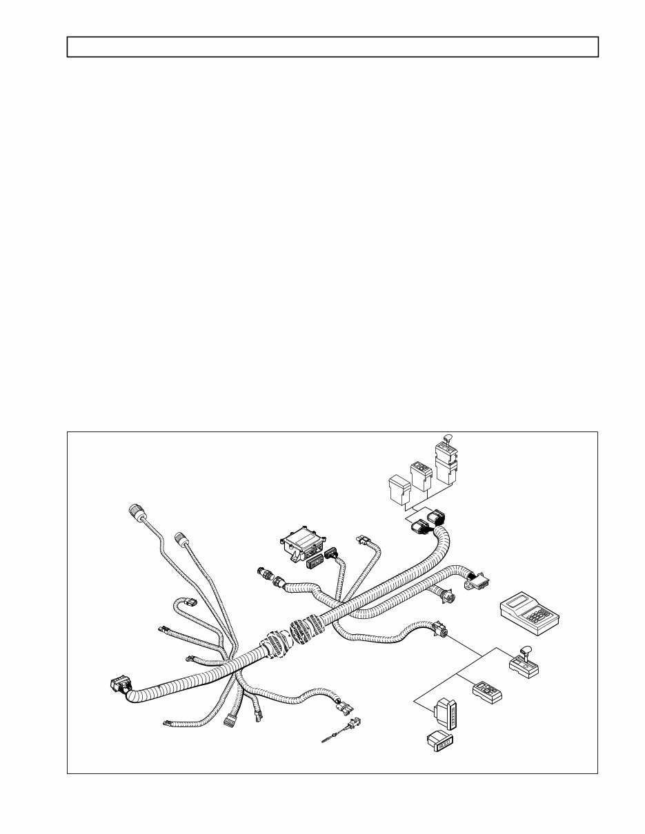
Figure 1–1. WTEC II Electronic Control Components (Units Produced Before 9/94)
7 8 9
4 5 6
1 2 3
0 ENTER =
x
–
+
–
OPTIONAL
DEUTSCH DDR
CONNECTOR
INTEGRAL ECU/
SHIFT SELECTORS
REMOTE
ECU
RETARDER
MODULATION
REQUEST (RMR)
SENSOR CONNECTOR
ELECTRONIC
CONTROL
UNIT
(ECU)
CONNECTORS
DIAGNOSTIC
DATA READER (DDR)
CONNECTOR
PRO-LINK
®
DIAGNOSTIC TOOL
J 38538-A
THROTTLE
POSITION
SENSOR
VEHICLE
INTERFACE
MODULE
(VIM)
MD/B 300/B 400
RETARDER CONNECTOR
(INCLUDES OUTPUT
SPEED SENSOR)
MD 3070
TRANSFER CASE
CONNECTOR
OUTPUT SPEED
SENSOR
*CONNECTOR
TRANSMISSION
CONNECTOR
ENGINE
SPEED
SENSOR
CONNECTOR
V01634
TPS
CONNECTOR
TURBINE
SPEED
SENSOR
CONNECTOR
(HD/B 500)
HD/B 500
RETARDER
TEMPERATURE
SENSOR
CONNECTOR
REMOTE SERIAL
INTERFACE
CONNECTOR
REMOTE
PUSHBUTTON SHIFT
SELECTOR
STRIP PUSHBUTTON
SHIFT SELECTOR
REMOTE
LEVER SHIFT
SELECTOR
RETARDER “K”
CONNECTOR
(HD/B 500)
HD/MD/B RETARDER
ACCUMULATOR “H”
SOLENOID
CONNECTOR
OPTIONAL
BULKHEAD
CONNECTOR
WIRING
HARNESS
NOTE: Illustration is not to scale.
*All HD/B 500 models
All Non-Retarder MD/B 300/B 400 models
1 2 D N R
D
N
R
VEHICLE
INTERFACE
WIRING
(VIW)
CONNECTOR
S ECTION 1 — GENERAL DESCRIPTION
WTEC II ELECTRONIC CONTROLS TROUBLESHOOTING MANUAL
1–2 Copyright © 1998 General Motors Corp.
GENERAL DESCRIPTION
Figure 1–2. WT Electronic Control Unit Components (Units Produced 9/94–12/97)
Figure 1–3 is a block diagram of the basic system’s inputs and outputs.
Figure 1–3. Electronic Control Unit Block Diagram
7 8 9
4 5 6
1 2 3
0 ENTER =
x
–
+
–
OPTIONAL
DEUTSCH DDR
CONNECTOR
INTEGRAL ECU/
SHIFT SELECTORS
REMOTE
ECU
PRO-LINK
®
DIAGNOSTIC TOOL
J 38538-A
THROTTLE
POSITION
SENSOR
MD/B 300/B 400
RETARDER CONNECTOR
(INCLUDES OUTPUT
SPEED SENSOR)
MD 3070
TRANSFER CASE
CONNECTOR
OUTPUT SPEED
SENSOR
*CONNECTOR
TRANSMISSION
CONNECTOR
ENGINE
SPEED
SENSOR
CONNECTOR
V01587
TPS
CONNECTOR
TURBINE
SPEED
SENSOR
CONNECTOR
(HD/B 500)
HD/B 500
RETARDER
TEMPERATURE
SENSOR
CONNECTOR
REMOTE SERIAL
INTERFACE
CONNECTOR
RETARDER “K”
CONNECTOR
(HD/B 500)
HD/MD/B RETARDER
ACCUMULATOR “H”
SOLENOID
CONNECTOR
OPTIONAL
BULKHEAD
CONNECTOR
WIRING
HARNESS
NOTE: Illustration is not to scale.
*All HD/B 500 models
All Non-Retarder MD/B 300/B 400 models
1 2 D N R
D
N
R
ELECTRONIC
CONTROL
UNIT
(ECU)
CONNECTORS
DIAGNOSTIC
DATA READER (DDR)
CONNECTOR
VEHICLE
INTERFACE
MODULE
(VIM)
VEHICLE
INTERFACE
WIRING
(VIW)
CONNECTOR
RETARDER
MODULATION
REQUEST (RMR)
SENSOR CONNECTOR
REMOTE
PUSHBUTTON SHIFT
SELECTOR
STRIP PUSHBUTTON
SHIFT SELECTOR
REMOTE
LEVER SHIFT
SELECTOR
SHIFT SELECTOR
RANGE AND
MODE SWITCH
TONE/DISPLAY
VIM
INPUTS OUTPUTS
ECU
SPEED SENSORS
THROTTLE POSITION SENSOR
RETARDER MODULATION
V01812
TEMPERATURE SENSOR
(SUMP/RETARDER)
SOLENOIDS
OIL LEVEL SENSOR
C3 PRESSURE SWITCH
Copyright © 1998 General Motors Corp. 1–3
GENERAL DESCRIPTION
WTEC II ELECTRONIC CONTROLS TROUBLESHOOTING MANUAL
1–2. ELECTRONIC CONTROL UNIT (ECU)
The ECU (Figure 1–4) contains the microcomputer which is the brain of the control system. The ECU receives and
processes information defining: shift selector position, throttle position, sump/retarder temperature, engine speed,
turbine speed, and transmission output speed. The ECU uses the information to control transmission solenoids and
valves, supply system status, and provide diagnostic information.
The ECU contains an Electronically Erasable Programmable Read Only Memory (EEPROM) which is
programmed with the shift calibration and other data for a specific transmission assembly, engine, and vehicle
vocation.
Figure 1–4. Electronic Control Unit (ECU)
1–3. SHIFT SELECTOR
Pushbutton and lever shift selectors are available for the WT Series. Either shift selector may be ordered attached to
(integral with), or remote from, the ECU. Both shift selectors are equipped with a digital display. However, the
strip pushbutton shift selector does not have a digital display.
On the shift selectors, between the range selected and the range monitored (attained) digits, is a MODE ON
indicator position. During normal transmission operation MODE ON indicates that a secondary or special
operating condition has been selected by pressing the MODE button. In diagnostic display mode, MODE ON
indicates the displayed diagnostic code is active. There is a SERVICE indicator icon under the MODE ON
indicator. It is illuminated when codes 21 XX, 63 00, and 66 00 are active (for ECUs programmed after 9/26/94).
When a transmission fault occurs that causes the DO NOT SHIFT light to turn on, the shift selector sounds a tone
to indicate transmission shifting is restricted.
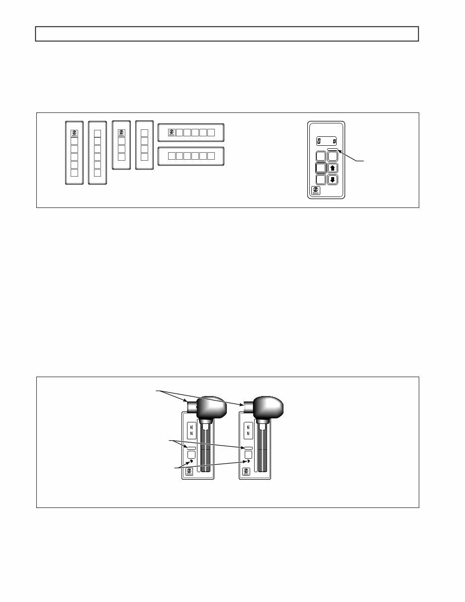
A. Pushbutton Shift Selector (Figure 1–5)
The full-function pushbutton shift selector has six (6) buttons and a digital display. The six buttons
are: R (Reverse), N (Neutral), D (Drive), ⇑ ( Up ) , ⇓ ( Down ) , and MODE . Manual forward range
downshifts; upshifts are made by pressing the ⇑ ( Up ) or ⇓ ( Down ) arrow buttons after selecting
D (Drive). The N (Neutral) button has a raised lip to aid in finding it by touch. The digital display
on the pushbutton selector indicates the range selected on the left side and the range monitored
(attained) on the right side. The MODE button is pressed to select a secondary or special operating
condition, such as ECONOMY shift schedule. The vehicle dimmer-control changes display
brightness. Diagnostic information is obtained by pressing the ⇑ (Up) and ⇓ (Down) arrow buttons
at the same time.
V00626.01
ECU
WTEC II ELECTRONIC CONTROLS TROUBLESHOOTING MANUAL
1–4 Copyright © 1998 General Motors Corp.
GENERAL DESCRIPTION
A strip pushbutton shift selector does not have a MODE button, SERVICE icon, or diagnostic
display capability. The Pro-Link
®
9000 or a customer-furnished remote display must be used for
diagnostic purposes.
Figure 1–5. Pushbutton Shift Selectors
B. Lever Shift Selector (Figure 1–6)
The lever shift selector can only be ordered with as many as six forward range positions (seven for
the MD 3070), as well as R (Reverse) and N (Neutral). The shift hold mechanism is released by
pressing a button on the side of the shift handle. The range selector lever can be moved freely
between numbered forward ranges. Press and hold the shift hold button to move into or out of the
D (Drive) position or when moving into or out of N (Neutral) or R (Reverse).
The digital display on the lever selector indicates the selected range at the top and the range
monitored (attained) at the bottom. A MODE button and a recessed DISPLAY MODE button are
also on the face of the lever shift selector. The MODE button is pressed to select a secondary or
special operating condition, such as ECONOMY shift schedule. Diagnostic information is obtained
by pressing the DISPLAY MODE button. The vehicle dimmer-control changes display brightness.
Figure 1–6. Six-Speed And Seven-Speed Lever Shift Selectors
R
N
D
MODE
MODE ON
SERVICE
SELECT POSITION
1 2 D N R
1
2
D
N
R
2
1
3
D
N
R
D
N
R
1
D
N
R 2 1 3 D N R
V01588
MODE ID
PUSHBUTTON
SELECTOR
STRIP PUSHBUTTON
SHIFT SELECTORS
SELECT
MONITOR
MODE ON
MODE
1
2
3
4
5
D
N
R
SELECT
MONITOR
MODE ON
SERVICE SERVICE
MODE
1
2
3
4
5
6
D
N
R
V01589
SIX-SPEED
LEVER SELECTOR
DISPLAY MODE BUTTON
MODE ID
HOLD OVERRIDE BUTTON
SEVEN-SPEED
LEVER SELECTOR
You're Reading a Preview
What's Included?
Lifetime Access
Access PDF Contents & Bookmarks
Print one or all pages of your manual