Copyright© 2005 General Motors Corp.
Welcome to the TS3353EN Troubleshooting Manual. We make every effort to keep our service
information current and accurate. Because of the time lag involved with writing and printing processes,
the transmission TCM may report a code that has not yet been added to this document. If you encounter
a code that is not yet in this publication, please call the Allison Transmission Technical Assistance Center
at 1-800-252-5283.
Go to the Table of Contents.
PREFACE
CEC2 ELECTRONIC CONTROLS TROUBLESHOOTING MANUAL
Printed in USA Copyright © 2005 General Motors Corp.
Allison Transmission, General Motors Corporation
P.O. Box 894 Indianapolis, Indiana 46206-0894
www.allisontransmission.com
Allison Transmission
Troubleshooting
Manual
2005 DECEMBER
TS3353EN
5000, 6000, 8000, 9000 Series Transmissions
Commercial Electronic Controls 2 (CEC2)
M 5610A M 5610AR
S 5610H S 5610MR S 5610M
M 6610A M 6610AR
S 6610H S 6610HR S6610M S 6610MR
M 8610A M 8610AR
S 8610H S 8610HR S 8610M S 8610MR
M 9610A M 9610AR
S 9610A S 9610AR S 9610M S 9610MR
S 9805M S 9805MR
S 9810A S 9810AR S 9810H S 9810HR
S 9810M S 9810MR
COMMERCIAL ELECTRONIC CONTROLS 2 (CEC2) TROUBLESHOOTING MANUAL
ii Copyright © 2005 General Motors Corp.
This manual provides troubleshooting information for Allison Transmission (AT), 5000, 6000, 8000, and
9000 Series Off-Highway Transmissions which have CEC2. Service Manuals SM1866EN (5000, 6000),
SM1228EN (8000) and SM1833EN (9000), plus Parts Catalogs PC1860EN (5000, 6000), PC1249EN (8000), and
PC1830EN (9000) may be used in conjunction with this manual.
This manual includes:
• Description of the CEC2 system
• Description of the electronic control system components
• Description of diagnostic codes, system responses to faults, and troubleshooting
• Wire, terminal, and connector repair information.
Specific instructions for using many of the available or required service tools and equipment are not included in
this manual. The service tool manufacturer will furnish instructions for using the tools or equipment.
Additional information may be published from time to time in Service Information Letters (SIL) and will be
included in future revisions of this and other manuals. Please use these SILs to obtain up-to-date information
concerning Allison Transmission products.
This publication is revised periodically to include improvements, new models, special tools, and procedures. A
revision is indicated by a letter suffix added to the publication number. Check with your Allison Transmission
service outlet for the currently applicable publication. Additional copies of this publication may be purchased from
authorized Allison Transmission service outlets or from:
SGI, Inc.
Attn: Allison Literature Fulfillment Desk
8350 Allison Avenue
Indianapolis, IN 46268
TOLL FREE: 888-666-5799
INTERNATIONAL: 317-471-4995
Take time to review the Table of Contents and the manual. Reviewing the Table of Contents will aid you in quickly
locating information.
NOTE: Allison Transmission provides service of wiring harnesses and wiring harness components as follows:
• Repair parts for the internal wiring harness and for wiring harness components attached to the
shift selector will be available through the Allison Transmission Parts Distribution Center (PDC).
Use the P/N from your appropriate parts catalog or from Appendix C in this manual. Allison
Transmission is responsible for warranty on these parts.
• Repair parts for the external harnesses and external harness components must be obtained from
St. Clair Technologies Inc. (SCTI). SCTI provides parts to any Allison customer or OEM and is
responsible for warranty on these parts. SCTI recognizes AT, manufacturers, and SCTI part
numbers. SCTI provides a technical HELPLINE at 519-627-1673 (Wallaceburg). SCTI will have
parts catalogs available. The SCTI addresses and phone numbers for parts outlets are:
• St. Clair Technologies, Inc. stocks an external harness repair kit as a source for some external
harness repair parts. SCTI is the source for external harness repair parts.
St. Clair Technologies, Inc
920 Old Glass Road
Wallaceburg, Ontario N8A 4L8
Phone: 519-627-1673
Fax: 519-627-4227
St. Clair Technologies, Inc.
Calle Damanti S/N Col
Guadalupe–Guaymas
Sonora, Mexico 85440
Phone: 011-526-2222-43834
Fax: 011-526-2222-43553
FOREWORD—H o w to U se T h is Man u al
Copyright © 2005 General Motors Corp. iii
IT IS YOUR RESPONSIBILITY to be completely familiar with the warnings and cautions
used in this manual. These warnings and cautions advise against using specific service
procedures that can result in personal injury, equipment damage, or cause the equipment to
become unsafe. These warnings and cautions are not exhaustive. Allison Transmission could
not possibly know, evaluate, or advise the service trade of all conceivable procedures by which
service might be performed or of the possible hazardous consequences of each procedure.
Consequently, Allison Transmission has not undertaken any such broad evaluation.
Accordingly, ANYONE WHO USES A SERVICE PROCEDURE OR TOOL WHICH IS NOT
RECOMMENDED BY ALLISON TRANSMISSION MUST first be thoroughly satisfied
that neither personal safety nor equipment safety will be jeopardized by the service
procedures used.
Also, be sure to review and observe WARNINGS, CAUTIONS, and NOTES provided by the
vehicle manufacturer and/or body builder before servicing the Allison transmission in that
vehicle.
Proper service and repair is important to the safe and reliable operation of the equipment.
The service procedures recommended by Allison Transmission and described in this manual
are effective methods for performing troubleshooting operations. Some procedures require
using specially designed tools. Use special tools when and in the manner recommended.
WARNINGS, CAUTIONS, AND NOTES
Three types of headings are used in this manual to attract your attention:
NOTE: Is used when an operating procedure, practice, etc., is essential to highlight.
WARNING!
Is used when an operating procedure, practice, etc., which, if not correctly followed,
could result in injury or loss of life.
CAUTION:
Is used when an operating procedure, practice, etc., which, if not strictly observed, could
result in damage to or destruction of equipment.
COMMERCIAL ELECTRONIC CONTROLS 2 (CEC2) TROUBLESHOOTING MANUAL
The WARNINGS, CAUTIONS, and NOTES in this manual apply only to the Allison transmission
and not to other vehicle systems which may interact with the transmission. Be sure to review and
observe any vehicle system information provided by the vehicle manufacturer and/or body builder
at all times the Allison transmission is being serviced.
IMPORTANT SAFETY NOTICE
COMMERCIAL ELECTRONIC CONTROLS 2 (CEC2) TROUBLESHOOTING MANUAL
iv Copyright © 2005 General Motors Corp.
TRADEMARKS USED IN THIS MANUAL
The following trademarks are the property of the companies indicated:
• LPS
®
Cleaner is a registered trademark of LPS Laboratories.
• Loctite
®
is a registered trademark of the Loctite Corporation.
• Teflon
®
is a registered trademark of the DuPont Corporation.
• Pro-Link
®
is a registered trademark of MicroProcessor Systems, Inc.
• Allison DOC™ For PC–Service Tool is a trademark for General Motors Corporation
IN T RODU CT ION
Copyright © 2005 General Motors Corp. v
Page
Foreword . . . . . . . . . . . . . . . . . . . . . . . . . . . . . . . . . . . . . . . . . . . . . . . . . . . . . . . . . . . . . . . . . . . . . . . . . . . . . ii
SAFETY INFORMATION
Important Safety Notice . . . . . . . . . . . . . . . . . . . . . . . . . . . . . . . . . . . . . . . . . . . . . . . . . . . . . . . . . . . . iii
Warnings, Cautions, and Notes . . . . . . . . . . . . . . . . . . . . . . . . . . . . . . . . . . . . . . . . . . . . . . . . . . . . . . . iii
Trademarks Used in This Manual . . . . . . . . . . . . . . . . . . . . . . . . . . . . . . . . . . . . . . . . . . . . . . . . . . . . . iv
SECTION 1. GENERAL DESCRIPTION
1–1. TRANSMISSION . . . . . . . . . . . . . . . . . . . . . . . . . . . . . . . . . . . . . . . . . . . . . . . . . . . . . . . . . . . . . . . 1–1
1–2. ELECTRONIC CONTROL UNIT (ECU) . . . . . . . . . . . . . . . . . . . . . . . . . . . . . . . . . . . . . . . . . . . . 1–3
1–3. SHIFT SELECTOR . . . . . . . . . . . . . . . . . . . . . . . . . . . . . . . . . . . . . . . . . . . . . . . . . . . . . . . . . . . . . 1–3
A. Pushbutton Shift Selector . . . . . . . . . . . . . . . . . . . . . . . . . . . . . . . . . . . . . . . . . . . . . . . . . . . . . . 1–3
B. Lever Shift Selector . . . . . . . . . . . . . . . . . . . . . . . . . . . . . . . . . . . . . . . . . . . . . . . . . . . . . . . . . . . 1–4
1–4. THROTTLE POSITION SENSOR . . . . . . . . . . . . . . . . . . . . . . . . . . . . . . . . . . . . . . . . . . . . . . . . . . 1–4
1–5. SPEED SENSORS . . . . . . . . . . . . . . . . . . . . . . . . . . . . . . . . . . . . . . . . . . . . . . . . . . . . . . . . . . . . . . 1–5
1–6. ELECTRO-HYDRAULIC VALVE COMPONENTS . . . . . . . . . . . . . . . . . . . . . . . . . . . . . . . . . . . . 1–5
1–7. WIRING HARNESSES . . . . . . . . . . . . . . . . . . . . . . . . . . . . . . . . . . . . . . . . . . . . . . . . . . . . . . . . . . 1–6
A. External Wiring Harness . . . . . . . . . . . . . . . . . . . . . . . . . . . . . . . . . . . . . . . . . . . . . . . . . . . . . . . 1–6
B. Internal Wiring Harnesses . . . . . . . . . . . . . . . . . . . . . . . . . . . . . . . . . . . . . . . . . . . . . . . . . . . . . . 1–8
1–8. VEHICLE INTERFACE MODULE . . . . . . . . . . . . . . . . . . . . . . . . . . . . . . . . . . . . . . . . . . . . . . . . . 1–9
1–9. AUTODETECT FEATURE . . . . . . . . . . . . . . . . . . . . . . . . . . . . . . . . . . . . . . . . . . . . . . . . . . . . . . . 1–9
SECTION 2. DEFINITIONS AND ABBREVIATIONS
2–1. CHECK TRANS LIGHT . . . . . . . . . . . . . . . . . . . . . . . . . . . . . . . . . . . . . . . . . . . . . . . . . . . . . . . . . 2–1
2–2. DIAGNOSTIC DATA READER . . . . . . . . . . . . . . . . . . . . . . . . . . . . . . . . . . . . . . . . . . . . . . . . . . . 2–1
2–3. ABBREVIATIONS . . . . . . . . . . . . . . . . . . . . . . . . . . . . . . . . . . . . . . . . . . . . . . . . . . . . . . . . . . . . . . 2–2
SECTION 3. BASIC KNOWLEDGE
3–1. BASIC KNOWLEDGE REQUIRED . . . . . . . . . . . . . . . . . . . . . . . . . . . . . . . . . . . . . . . . . . . . . . . . 3–1
3–2. USING THE TROUBLESHOOTING MANUAL . . . . . . . . . . . . . . . . . . . . . . . . . . . . . . . . . . . . . . 3–2
3–3. SYSTEM OVERVIEW . . . . . . . . . . . . . . . . . . . . . . . . . . . . . . . . . . . . . . . . . . . . . . . . . . . . . . . . . . . 3–2
3–4. IMPORTANT INFORMATION IN THE TROUBLESHOOTING PROCESS . . . . . . . . . . . . . . . . 3–2
3–5. TESTING FOR OPENS, SHORTS BETWEEN WIRES, AND SHORTS-TO-GROUND . . . . . . . 3–3
3–6. TESTING AT TRANSMISSION CONNECTOR AND THE INTERNAL HARNESS
FOR OPENS, SHORTS BETWEEN WIRES, AND SHORTS-TO-GROUND . . . . . . . . . . . . . . . . 3–5
SECTION 4. WIRE TESTING PROCEDURES
4–1. BEGINNING THE TROUBLESHOOTING PROCESS . . . . . . . . . . . . . . . . . . . . . . . . . . . . . . . . . 4–1
4–2. GENERAL TROUBLESHOOTING OF PERFORMANCE COMPLAINTS . . . . . . . . . . . . . . . . . 4–1
4–3. SHIFT INHIBITS—NO DIAGNOSTIC CODES . . . . . . . . . . . . . . . . . . . . . . . . . . . . . . . . . . . . . . 4–7
TABLE OF CONTENTS
CEC2 ELECTRONIC CONTROLS TROUBLESHOOTING MANUAL
vi Copyright © 2005 General Motors Corp.
TABLE OF CONTENTS ( C o n t ' d)
CEC2 ELECTRONIC CONTROLS TROUBLESHOOTING MANUAL
Page
SECTION 5. DIAGNOSTIC CODES
5–1. DIAGNOSTIC CODE MEMORY . . . . . . . . . . . . . . . . . . . . . . . . . . . . . . . . . . . . . . . . . . . . . . . . . . 5–1
5–2. CODE READING AND CODE CLEARING . . . . . . . . . . . . . . . . . . . . . . . . . . . . . . . . . . . . . . . . . 5–1
5–3. DIAGNOSTIC CODE RESPONSE . . . . . . . . . . . . . . . . . . . . . . . . . . . . . . . . . . . . . . . . . . . . . . . . . 5–3
5–4. SHIFT SELECTOR DISPLAYS RELATED TO ACTIVE CODES . . . . . . . . . . . . . . . . . . . . . . . . 5–3
5–5. DIAGNOSTIC CODE LIST AND DESCRIPTION . . . . . . . . . . . . . . . . . . . . . . . . . . . . . . . . . . . . . 5–4
SECTION 6. VEHICLE INTERFACE WIRING—MANDATORY (VIW-M)
6–1. ECU POWER . . . . . . . . . . . . . . . . . . . . . . . . . . . . . . . . . . . . . . . . . . . . . . . . . . . . . . . . . . . . . . . . . . 6–1
6–2. SYSTEM GROUNDS . . . . . . . . . . . . . . . . . . . . . . . . . . . . . . . . . . . . . . . . . . . . . . . . . . . . . . . . . . . . 6–2
6–3. POWER AND GROUND USING A BUS BAR . . . . . . . . . . . . . . . . . . . . . . . . . . . . . . . . . . . . . . . . 6–3
6–4. INSTALLING A MASTER DISCONNECT SWITCH . . . . . . . . . . . . . . . . . . . . . . . . . . . . . . . . . . 6–4
6–5. IGNITION POWER . . . . . . . . . . . . . . . . . . . . . . . . . . . . . . . . . . . . . . . . . . . . . . . . . . . . . . . . . . . . . 6–5
6–6. CHECK TRANS LIGHT . . . . . . . . . . . . . . . . . . . . . . . . . . . . . . . . . . . . . . . . . . . . . . . . . . . . . . . . . 6–6
6–7. NEUTRAL START . . . . . . . . . . . . . . . . . . . . . . . . . . . . . . . . . . . . . . . . . . . . . . . . . . . . . . . . . . . . . . 6–7
6–8. SPEEDOMETER SIGNAL . . . . . . . . . . . . . . . . . . . . . . . . . . . . . . . . . . . . . . . . . . . . . . . . . . . . . . . 6–8
6–9. REVERSE WARNING . . . . . . . . . . . . . . . . . . . . . . . . . . . . . . . . . . . . . . . . . . . . . . . . . . . . . . . . . . . 6–9
6–10. SHIFT SELECTOR/DISPLAY DIMMER . . . . . . . . . . . . . . . . . . . . . . . . . . . . . . . . . . . . . . . . . . . 6–10
6–11. SERIAL COMMUNICATION INTERFACE (SCI)—J1587/J1708 . . . . . . . . . . . . . . . . . . . . . . . . 6–11
6–12. COMMUNICATION INTERFACE—SAE J1939 . . . . . . . . . . . . . . . . . . . . . . . . . . . . . . . . . . . . . 6–12
SECTION 7. WIRING SCHEMATICS − OPTIONAL INPUT AND OUTPUT FUNCTIONS
7–1. CALIBRATION COMPATIBILITY . . . . . . . . . . . . . . . . . . . . . . . . . . . . . . . . . . . . . . . . . . . . . . . . . 7–2
7–2. INPUT FUNCTION . . . . . . . . . . . . . . . . . . . . . . . . . . . . . . . . . . . . . . . . . . . . . . . . . . . . . . . . . . . . . 7–3
7–3. OUTPUT FUNCTION . . . . . . . . . . . . . . . . . . . . . . . . . . . . . . . . . . . . . . . . . . . . . . . . . . . . . . . . . . 7–27
SECTION 8. CUTOMER MODIFIABLE CONSTANTS (CMC) . . . . . . . . . . . . . . . . . . . . . . . . . . . . 8–1
APPENDICES
A. IDENTIFICATION OF POTENTIAL CIRCUIT PROBLEMS . . . . . . . . . . . . . . . . . . . . . . . . . . . . A–1
B. WIRE/CONNECTOR CHART . . . . . . . . . . . . . . . . . . . . . . . . . . . . . . . . . . . . . . . . . . . . . . . . . . . . . B–1
C. CONNECTOR PART NUMBERS, TERMINAL PART NUMBERS,
TOOL PART NUMBERS, AND REPAIR INSTRUCTIONS . . . . . . . . . . . . . . . . . . . . . . . . . . . . . C–1
D. THROTTLE POSITION SENSOR ADJUSTMENT . . . . . . . . . . . . . . . . . . . . . . . . . . . . . . . . . . . . D–1
E. WELDING ON VEHICLE/VEHICLE INTERFACE MODULE . . . . . . . . . . . . . . . . . . . . . . . . . . E–1
F. HYDRAULIC SCHEMATICS . . . . . . . . . . . . . . . . . . . . . . . . . . . . . . . . . . . . . . . . . . . . . . . . . . . . . F–1
G. CEC2 WIRING SYSTEM/ECU WIRING SCHEMATICS . . . . . . . . . . . . . . . . . . . . . . . . . . . . . . . G–1
H. EXTERNALLY-GENERATED ELECTRONIC INTERFERENCE . . . . . . . . . . . . . . . . . . . . . . . . H–1
J. DIAGNOSTIC DATA READER INFORMATION . . . . . . . . . . . . . . . . . . . . . . . . . . . . . . . . . . . . . J–1
Copyright © 2005 General Motors Corp. 1–1
COMMERCIAL ELECTRONIC CONTROLS 2 (CEC2) TROUBLESHOOTING MANUAL
S ECTION 1—GENERAL DESCRIPTION
1–1. TRANSMISSION
The Commercial Electronic Controls 2 (CEC2) system features clutch control to provide superior shift quality over
a wide range of operating conditions.
The ranges available in CEC2-equipped Off-Highway transmissions are as follows.
• 5610, 6610, 9610—six forward, neutral, two reverses
• 8610—six forward, neutral, reverse
• 9805—eight forward, neutral
• 9810—eight forward, neutral
Figure 1–1 is a block diagram of the basic transmission system inputs and outputs.
Figure 1–1. Electronic Control Unit Block Diagram
Figure 1–2 shows the CEC2 electronic control components.
CEC2 consists of the following elements:
• Remote 12/24V Max Feature Sealed Electronic Control Unit (ECU)
• Remote Pushbutton or Lever Shift Selector
• Optional Secondary Shift Selector
• Throttle Position Sensor (TPS) (or electronic engine throttle data)
• Input, Turbine, and Output Speed Sensors
• Electro-Hydraulic Valve Bodies
• Wiring Harnesses
• Vehicle Interface Module (VIM)
NOTE: • All external harnesses are OEM supplied.
• The VIM is an OEM option.
SHIFT SELECTOR
RANGE AND
MODE SWITCH
DISPLAY
VIM
INPUTS OUTPUTS
ECU
SPEED SENSORS
THROTTLE POSITION SENSOR
V03469.01
TEMPERATURE SENSOR
(SUMP)
VEHICLE/ENGINE
COMMUNICATION LINKS
SOLENOIDS
COMMERCIAL ELECTRONIC CONTROLS 2 (CEC2) TROUBLESHOOTING MANUAL
1–2 Copyright © 2005 General Motors Corp.
GENERAL DESCRIPTION
.
Figure 1–2. CEC2 Components
B LUE B LUE B LUE B LUE
B LACK B LACK GRA GRA Y
R
N
D
M ODE
SELE CT
T R A NS M ISSION
MA IN V A LVE
BODY
C ONNE CT OR
VEHI C LE
IN T ERF AC E
M ODULE
(VI M )
VEHI C LE (V)
H A RNESS
T R A NS M ISSION ( T )
H A RNESS
ELE CT RONI C
C ON T ROL
UNI T
(E C U)
T PS
C ONNE CT OR
(OP T ION A L)
RE M O T E
LEVER
SELE CT OR
RE M O T E
PUSHBU TT ON
SELE CT OR
SHIF T
SELE CT OR
C ONNE CT OR
VIW–V
C ONNE CT OR
VIW–S
C ONNE CT OR
VI M
C ONNE CT ORS
PRO-LINK
®
DI AG NOS T I C
T OOL
DI AG NOS T I C T OOL
C ONNE CT OR
B u l khe ad C onn e ctor ( Optional )
T HRO TT LE
POSI T ION
SENSOR ( T PS)
T HRO TT LE POSI T ION
SENSOR ( T PS)
C ONNE CT OR
OU T PU T
SPEED SENSOR
C ONNE CT OR
T E M P SENSOR/
LO C KUP
C ONNE CT OR
T RI M
BOOS T
C ONNE CT OR
T URBINE
SPEED SENSOR
C ONNE CT OR
INPU T (EN G INE)
SPEED SENSOR
C ONNE CT OR
V 06 5 8 7 .0 1 .00
NOTE: Illustration is not to scale. Actual harness
configuration may differ from this illustration.
“S”
C ONNE CT OR
(BL AC K)
“ T ”
C ONNE CT OR
(BLUE)
“V”
C ONNE CT OR
( G R A Y)
SELE CT OR (S)
H A RNESS
J 1939
C ONNE CT OR
(OP T ION A L)
DEU T S C H
DI AG NOS T I C T OOL
C ONNE CT OR
(OP T ION A L)
S C I (J 1587)
C ONNE CT OR
(OP T ION A L)
A LLISON DO C
™
FOR
P C — SERVI C E T OOL
Copyright © 2005 General Motors Corp. 1–3
GENERAL DESCRIPTION
COMMERCIAL ELECTRONIC CONTROLS 2 (CEC2) TROUBLESHOOTING MANUAL
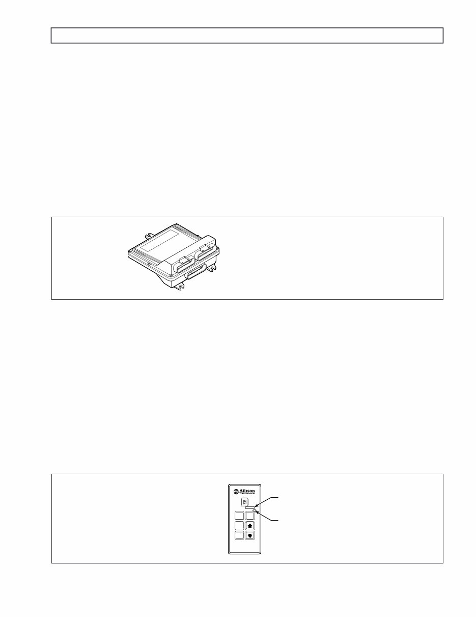
1–2. ELECTRONIC CONTROL UNIT (ECU)
The ECU (Figure 1–3) contains the microcomputer which is the brain of the control system. The ECU receives and
processes information defining:
The ECU uses the information to:
• Control transmission solenoids and valves.
• Supply system status.
• Provide diagnostic information.
Each ECU has a date code stamped on the label which is attached to the outer case of the ECU. This is the date
when the ECU passed final test. This date is commonly used to denote the change configuration level of the ECU.
It is normal for the ECU date displayed electronically to be a few days prior to the date shown on the label.
Figure 1–3. Electronic Control Unit (ECU)
1–3. SHIFT SELECTOR
Pushbutton and lever shift selectors for CEC2 are remote mounted from the ECU and connected to the ECU by a
wiring harness. Both of these shift selectors have a single digit LED display and a mode indicator LED. During
normal transmission operation, illumination of the LED indicator shows that a secondary or special operating
condition has been selected by pressing the MODE button. During diagnostic display mode, illumination of the
LED indicator shows that the displayed diagnostic code is active. Display brightness is regulated by the same
vehicle potentiometer that controls dash light display brightness. More information on both types of shift selectors
is continued below.
A. Pushbutton Shift Selector (Figure 1–4)
The full-function pushbutton shift selector has a MODE button and diagnostic display capability
through the single digit LED display. The full-function pushbutton shift selector has the following
six (6) pushbuttons:
Figure 1–4. Typical Full-Function Pushbutton Shift Selector
• Shift selector position • Sump temperature • Turbine speed
• Throttle position • Input speed • Transmission output speed
• R (Reverse) • D (Drive) • MODE
• N (Neutral) • ↓ (Down) and ↑ (Up) arrows
V 0 335 2.00.02
B LUE B LUE B LUE B LUE
B LACK B LACK GRAY
E C U
NO T E: ECU wirin g h arn e ss conn e ctor r e tain e rs
ar e indi v id u all y keye d and color-cod e d to
ma ke s u r e t h at t he prop e r conn e ctor is attac he d
to t he corr e ct ECU soc ke t. The color o f t he
conn e ctor r e tain e r s h o u ld matc h t he color o f
t he conn e ctor strain r e li ef ( s ee A pp e ndix C ,
Para g rap h C–1) .
R
N
D
M ODE
V 06 5 88.0 1 .00
M ODE ID
M ODE INDI CAT OR (LED)
PUSHBU TT ON
SELE CT OR
You're Reading a Preview
What's Included?
Lifetime Access
Access PDF Contents & Bookmarks
Print one or all pages of your manual