TABLE OF CONTENTS SECTION I INTRODUCTION 1–1 ABOUT THIS MANUAL ............................... 7 SECTION II PREVENTIVE MAINTENANCE 2–1 PERIODIC INSPECTION AND CARE ...................... 18 2–2 IMPORTANCE OF PROPER TRANSMISSION FLUID LEVEL ....... 19 2–3 TRANSMISSION FLUID CHECK ......................... 19 2–4 KEEPING FLUID CLEAN .............................. 25 2–5 FLUID RECOMMENDATIONS ........................... 25 2–6 TRANSMISSION FLUIDAND FILTER CHANGE INTERVALS ...... 26 2–7 TRANSMISSION FLUID CONTAMINATION .................. 30 2–8 TRANSMISSION FLUID AND FILTER CHANGE PROCEDURE ..... 31 2–9 FLUID LEAK DIAGNOSIS ............................. 33 2–10 BREATHER ...................................... 35 2–11 TROUBLESHOOTING ............................... 36 2–12 TRANSMISSION STALL TEST .......................... 42 SECTION III REMOVING TRANSMISSION 3–1 DRAINING TRANSMISSION ............................ 47 3–2 DISCONNECTING CONTROLS .......................... 47 3–3 UNCOUPLING FROM DRIVELINE, ENGINE, AND VEHICLE ...... 49 3–4 REMOVING THE TRANSMISSION ........................ 50 3–5 REMOVING OUTPUT FLANGE OR YOKE ................... 50 SECTION IV TRANSMISSION PREPARATION 4–1 CHECKING INPUT COMPONENTS ....................... 51 4–2 INSTALLING OUTPUT FLANGE OR YOKE .................. 51 4–3 INSTALLING PTO ................................... 52 4–4 INSTALLING FILL TUBE AND SEAL ...................... 52 4–5 CHECKING PLUGS AND OPENINGS ...................... 53 3
SECTION V PREPARING VEHICLE FOR TRANSMISSION INSTALLATION 5–1 ENGINE, TRANSMISSION ADAPTATION REQUIREMENTS ....... 54 5–2 CHECKING FLEXPLATE DRIVE ASSEMBLY ................. 57 5–3 CHASSIS AND DRIVELINE INSPECTION ................... 58 5–4 COOLER, FILTER, AND LINES .......................... 59 5–5 CHECKING CONTROLS .............................. 60 SECTION VI INSTALLING TRANSMISSION INTO VEHICLE 6–1 HANDLING ....................................... 64 6–2 MOUNTING TO ENGINE .............................. 64 6–3 INSTALLING TRANSMISSION MOUNTING COMPONENTS ....... 65 6–4 COUPLING TO DRIVELINE ............................ 65 6–5 CONNECTING OUTPUT RETARDER ACCUMULATOR .......... 65 6–6 CONNECTING POWER TAKEOFF CONTROLS ................ 66 6–7 CONNECTING PARKING BRAKE CONTROL ................. 67 6–8 CONNECTING COOLER .............................. 67 6–9 CONNECTING ELECTRICAL COMPONENTS ................. 67 6–10 CONNECTING SPEEDOMETER DRIVE .................... 69 6–11 FILLING HYDRAULIC SYSTEM ........................ 69 6–12 INSTALLATION CHECKLIST .......................... 70 SECTION VII CHECKS AND ADJUSTMENTS 7–1 INSTALLATION CHECKLIST ........................... 71 7–2 ROAD TEST AND VEHICLE OPERATION CHECKLIST .......... 73 SECTION VIII CUSTOMER SERVICE 8–1 OWNER ASSISTANCE ................................ 75 8–2 SERVICE LITERATURE ............................... 75 4
TRADEMARK USAGE The following trademarks are the property of the companies indicated: • Allison DOC™ is a trademark of General Motors Corporation. • DEXRON ® is a registered trademark of the General Motors Corporation. • TranSynd™ is a trademark of Castrol Ltd. 5
WARNINGS, CAUTIONS, NOTES IT IS YOUR RESPONSIBILITY to be completely familiar with the warnings and cautions described in this manual. It is, however, important to understand that these warnings and cautions are not exhaustive. Allison Transmission could not possibly know, evaluate, and advise the service trade of all conceivable ways in which service might be done or of the possible hazardous consequences of each way. The vehicle manufacturer is responsible for providing information related to the operation of vehicle systems (including appropriate warnings, cautions, and notes). Consequently, Allison Transmission has not undertaken any such broad evaluation. Accordingly, ANYONE WHO USES A SERVICE PROCEDURE OR TOOL WHICH IS NOT RECOMMENDED BY ALLISON TRANSMISSION OR THE VEHICLE MANUFACTURER MUST first be thoroughly satisfied that neither personal safety nor equipment safety will be jeopardized by the service methods selected. Proper service and repair is important to the safe, reliable operation of the equipment. The service procedures recommended by Allison Transmission (or the vehicle manufacturer) and described in this manual are effective methods for performing service operations. Some of these service operations require the use of tools specially designed for the purpose. The special tools should be used when and as recommended. Three types of headings are used in this manual to attract your attention. These warnings and cautions advise of specific methods or actions that can result in personal injury, damage to the equipment, or cause the equipment to become unsafe. WARNING: A warning is used when an operating procedure, practice, etc., if not correctly followed, could result in personal injury or loss of life. CAUTION: A caution is used when an operating procedure, practice, etc., if not strictly observed, could result in damage to or destruction of equipment. NOTE: A note is used when an operating procedure, practice, etc., is essential to highlight. 6
1–1. ABOUT THIS MANUAL This manual is a mechanic’s reference for maintaining, removing, or installing 3000 and 4000 Product Family transmissions with Allison 4 th Generation Controls. All features of the transmission and the vehicle involved in installation procedures are discussed. The information presented will help the mechanic maintain, remove, or install the transmission in a manner that assures satisfactory operation and long service life. For additional detailed information, refer to the appropriate transmission service manual and electronic controls troubleshooting manual. Unless specifically indicated otherwise, this manual refers to all Allison 4 th Generation Controls for 3000 and 4000 Product Family transmissions, except for the 3700 SP model. The differences between the various transmission models are explained as required. INTRODUCTION Section I 7
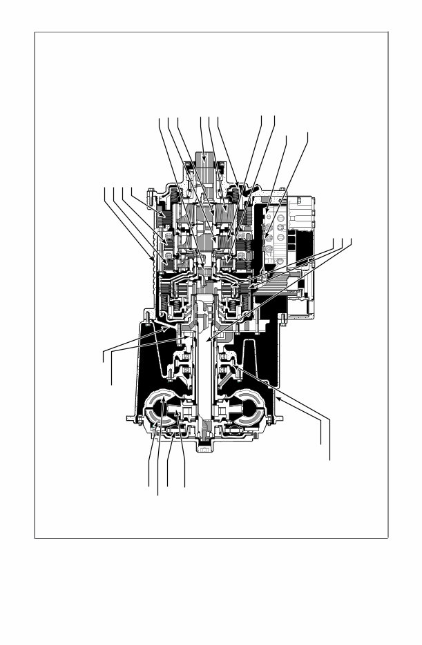
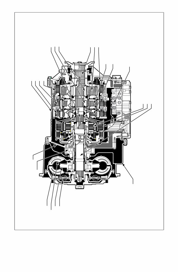
V03350.06.00 OIL LEVEL SENSOR P2 MODULE P1 MODULE CONVERTER MODULE • TURBINE • PUMP • LOCKUP CLUTCH/DAMPER • STATOR CONVERTER HOUSING MODULE • CONVERTER HOUSING • PTO DRIVE GEAR ROTATING CLUTCH MODULE • C1 CLUTCH • C2 CLUTCH • TURBINE SHAFT CONTROL MODULE • ELECTRO-HYDRAULIC CONTROLS MAIN SHAFT MODULE • MAIN SHAFT • P2 SUN • P3 SUN MAIN HOUSING MODULE • MAIN HOUSING • C3 CLUTCH • C4 CLUTCH • C5 CLUTCH FRONT SUPPORT/OIL PUMP MODULE • FRONT SUPPORT • OIL PUMP REAR COVER MODULE • OUTPUT SHAFT • P3 • C5 PISTON Figure 1–1. 3000 Product Family Transmission—Cross Section (With PTO Provision) 8
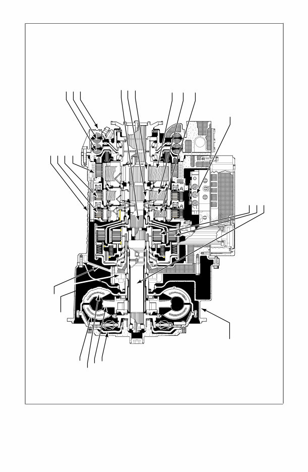
ROTATING CLUTCH MODULE • C1 CLUTCH • C2 CLUTCH • TURBINE SHAFT CONTROL MODULE • ELECTRO-HYDRAULIC CONTROLS P1 MODULE P2 MODULE MAIN HOUSING MODULE • MAIN HOUSING • C3 CLUTCH • C4 CLUTCH • C5 CLUTCH MAIN SHAFT MODULE • MAIN SHAFT • P2 SUN • P3 SUN REAR COVER MODULE • OUTPUT SHAFT • P3 MODULE • C5 PISTON V07286.01.00 CONVERTER MODULE • TURBINE • PUMP • STATOR • LOCKUP • CLUTCH/DAMPER CONVERTER HOUSING MODULE • CONVERTER HOUSING FRONT SUPPORT/OIL PUMP MODULE • FRONT SUPPORT • OIL PUMP Figure 1–2. 4000 Product Family Transmission—Cross Section 9
V07287.04.00 MAIN HOUSING MODULE • MAIN HOUSING • C3 CLUTCH • C4 CLUTCH • C5 CLUTCH ROTATING CLUTCH MODULE • C1 CLUTCH • C2 CLUTCH • TURBINE SHAFT CONTROL MODULE • ELECTRO-HYDRAULIC CONTROLS P3 MODULE P2 MODULE P1 MODULE MAIN SHAFT MODULE • MAIN SHAFT • P2 SUN • P3 SUN RETARDER MODULE • STATOR ASSEMBLY • ROTOR • HOUSING ASSEMBLY CONVERTER HOUSING MODULE • CONVERTER HOUSING FRONT SUPPORT/OIL PUMP MODULE • FRONT SUPPORT • OIL PUMP CONVERTER MODULE • TURBINE • PUMP • STATOR • LOCKUP CLUTCH/DAMPER Figure 1–3. 4000 Product Family Transmission—Cross Section (With Retarder) 10
The "Allison 3000 & 4000 Series Transmissions Service & Repair Manual Collection" is a comprehensive resource designed for technicians, mechanics, and enthusiasts. It covers an extensive range of models across various series, including the EVS, HS, MH, and more, catering to a broad spectrum of applications.
Key components of this collection include detailed service and repair manuals that provide procedures for troubleshooting, maintenance, and repair. These manuals contain schematics, technical specifications, and step-by-step guides for a deeper understanding of each transmission type.
Additionally, the collection includes bonus materials such as troubleshooting manuals specific to different generations of control systems, including WTEC II, WTEC III, and the latest 4th Generation models. Technicians' guides offer insights into transmission care for both the 3K and 4K series.
Principles of Operation Manuals for both the 3K and 4K series, along with their 4th Generation counterparts, provide a foundational understanding of how these transmissions operate, aiding in effective troubleshooting and repair. Mechanic's tips for various generations offer quick, actionable advice for common issues and maintenance best practices.
Furthermore, user guides like the Allison DOC 7.0 offer navigation for diagnostic software, while owner and operator manuals ensure end-users understand and follow operational guidelines. Cross-section diagrams provide a visual representation of the internal structure of the transmissions, aiding in identification and repair of internal components.
Additional resources, including specific troubleshooting guides for the MD HD B Series and model-year prognostics job aids, offer further support, ensuring users have access to a well-rounded set of tools for addressing a wide array of maintenance and repair scenarios.
In summary, this collection is an indispensable resource for anyone looking to perform detailed service, repair, or maintenance on the Allison 3000 & 4000 series transmissions, combining technical depth with practical guidance to ensure the longevity and optimal performance of these sophisticated systems.
Recently Viewed
5,521,897Happy Clients
2,594,462eManuals
1,120,453Trusted Sellers
15Years in Business
Price:
Actual Price:
Allison 3000 & 4000 Series Transmissions Service & Repair Manual Collection