

Allison 1000 & 2000 Transmission Service & Repair Manual
What's Included?
Fast Download Speeds
Online & Offline Access
Access PDF Contents & Bookmarks
Full Search Facility
Print one or all pages of your manual

INDEX
Copyright © ATSG 2000 May, 2000
ALLISON 1000/2000 SERIES
CAUTION: ATSG service manuals are intended for use by professional,
qualified technicians. Attempting repairs or service without the proper
training, tools and equipment could cause injury to you or others and damage
to the vehicle that may cause it not to operate properly.
CLUTCH AND SOLENOID APPLICATION CHART ........................................................................................... 4
TRANSMISSION IDENTIFICATION TAG INFORMATION .............................................................................. 5
GENERAL DESCRIPTION AND OPERATION .................................................................................................... 6
ELECTRICAL OPERATION ................................................................................................................................... 9
THROTTLE POSITION SENSOR .............................................. ........................................................................... 10
NEUTRAL START BACK UP SWITCH ................................................................................................................. 11
TRANSMISSION CONTROL MODULE CONNECTOR IDENTIFICATION .................................................... 12
DIAGNOSTIC TROUBLE CODE IDENTIFICATION ......................................................................................... 14
SOLENOID IDENTIFICATION AND OPERATION ............................................................................................. 16
INTERNAL WIRING HARNESS SCHEMATIC AND RESISTANCE CHART ................................................... 18
EXTERNAL WIRING HARNESS SCHEMATIC AND TERMINAL IDENTIFICATION ................................... 19
PRESSURE SWITCH ASSEMBLY IDENTIFICATION AND OPERATION ....................................................... 20
RETRIEVING DIAGNOSTIC TROUBLE CODES ................................................................................................ 22
LINE PRESSURE TESTS ................................................... ................................................................................... 23
BELL HOUSING OIL PASSAGE IDENTIFICATION ......................................................................................... 24
MAIN CASE "FRONT" OIL PASSAGE IDENTIFICATION .............................................................................. 26
MAIN CASE "REAR" OIL PASSAGE IDENTIFICATION ................................................................................. 27
OIL PUMP COVER OIL PASSAGE IDENTIFICATION ..................................................................................... 29
SHIFT VALVE BODY OIL PASSAGE IDENTIFICATION ................................................................................. 31
MAIN VALVE BODY "TOP VIEW" OIL PASSAGE IDENTIFICATION .......................................................... 32
MAIN VALVE BODY "BOTTOM VIEW" OIL PASSAGE IDENTIFICATION ................................................ 33
MAIN CASE "BOTTOM VIEW" OIL PASSAGE IDENTIFICATION ............................................................... 35
TRANSMISSION DISASSEMBLY PROCESS ...................................................................................................... 36
COMPONENT REBUILD
TRANSMISSION CASE ASSEMBLY .............................................................................................................. 53
OIL PUMP AND BELLHOUSING ASSEMBLY ............................................................................................ 55
FOUR DIFFERENT BELL HOUSINGS IDENTIFICATION ...................................................................... 66
C1/C2 CLUTCH HOUSING ASSEMBLY ....................................................................................................... 68
C1/C2 CLUTCH HOUSING SNAP RING IDENTIFICATION ..................................................................... 72
VALVE BODY ASSEMBLY ............................................................................................................................. 80
SOLENOID AIR CHECKS ............................................................................................................................... 83
EXTENSION HOUSING ASSEMBLY ............................................................................................................. 91
GEAR TRAIN PARTS ....................................................................................................................................... 96
CASE CLUTCH PARTS .................................................................................................................................... 100
FINAL TRANSMISSION ASSEMBLY PROCESS ................................................................................................ 102
BOLT IDENTIFICATION CHART ........................................................................................................................ 119
TORQUE SPECIFICATION CHART .................................................................................................................... 120
AUTOMATIC TRANSMISSION SERVICE GROUP
18639 S.W. 107TH AVENUE
MIAMI, FLORIDA 33157
(305) 670-4161
BACK
BACK
BACK
GO TO PAGE

INTRODUCTION
ALLISON 1000/2000 SERIES
1
No part of any ATSG publication may be reproduced, stored in any retrieval system or transmitted in any form or
by any means, including but not limited to electronic, mechanical, photocopying, recording or otherwise,
without written permission of Automatic Transmission Service Group. This includes all text illustrations,
tables and charts.
Beginning at the start of production for the 2000 model year, General Motors introduced two new Allison
automatic transmissions referred to as the 1000 Series and the 2000 Series, for light duty (8600-19850 GVW)
and medium duty (19850-3000 GVW) commercial trucks.
The 1000 and 2000 Series transmissions both have helical cut planetary gear systems to minimize noise
concerns and come in two different gear ratio configurations. The 1000 Series uses closer steps to improve the
shift quality that we now expect from an automatic transmission. The 2000 Series uses wider steps to
accommodate the greater vehicle weights associated with the 2000 Series. The gear ratios for both of the new
units are shown in this Manual.
The 1000 and 2000 Series transmissions have a Park position, Reverse, Neutral and five forward speeds with
5th gear being overdrive, and are completely electronic shift controlled. Notice that the standard General
Motors case connector has been utilized, and the Park/Neutral switch is exactly the same switch used currently
on the THM 4L60-E transmission. Two different bottom pan configurations are also provided to make these
units even more versitile. The 1000 and 2000 Series transmissions utilize five clutch packs (No Bands-No
Freewheels) to obtain the five forward gears and reverse. This manual will cover the dis-assembly, rebuild of all
components and re-assembly of both the 1000 and 2000 Series units.
Updated
October, 2003
DALE ENGLAND
FIELD SERVICE CONSULTANT
ED KRUSE
TECHNICAL CONSULTANT
WAYNE COLONNA
TECHNICAL SUPERVISOR
PETER LUBAN
TECHNICAL CONSULTANT
JIM DIAL
TECHNICAL CONSULTANT
GREGORY LIPNICK
TECHNICAL CONSULTANT
JERRY GOTT
TECHNICAL CONSULTANT
JON GLATSTEIN
TECHNICAL CONSULTANT
DAVID CHALKER
TECHNICAL CONSULTANT
MIKE SOUZA
TECHNICAL CONSULTANT
ROLAND ALVAREZ
TECHNICAL CONSULTANT
GERALD CAMPBELL
TECHNICAL CONSULTANT
"Portions of materials contained herein have been reprinted under
license from General Motors Corp, Service & Parts Operations."
The information and part numbers contained in this booklet have
been carefully compiled from industry sources known for their
reliability, but ATSG does not guarantee its accuracy.
Copyright © ATSG 2000
AUTOMATIC TRANSMISSION SERVICE GROUP
18639 S.W. 107TH AVENUE
MIAMI, FLORIDA 33157
(305) 670-4161
AUTOMATIC TRANSMISSION SERVICE GROUP
Technical Service Information
3
Copyright © 2000 ATSG
Allison Allison
Allison Allison
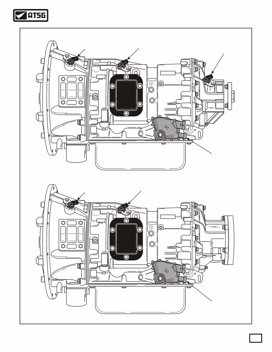
ALLISON 1000/2000 SERIES
TWO WHEEL DRIVE
FOUR WHEEL DRIVE
Engine Speed
Sensor
Engine Speed
Sensor
Turbine Speed
Sensor
Turbine Speed
Sensor
Neutral Start
Switch
Neutral Start
Switch
Output Speed
Sensor
Figure 1
AUTOMATIC TRANSMISSION SERVICE GROUP
Technical Service Information
4
Copyright © 2000 ATSG
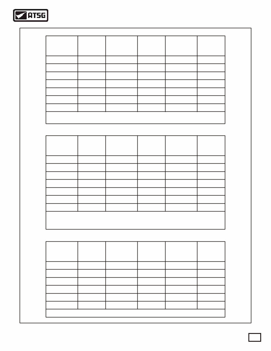
**
Range
Ratios
1000 2000
C2
Clut
C3
Clut
C4
Clut
C5
Clut
Sol
"A"
Sol
"B"
Sol
"C"
Sol
"D"
Sol
"E"
Sol
"F"
C1
Clut
Park
Reverse X
X X ON
ON
ON ON
ON ON
ON
ON ON
ON
ON ON
ON
ON
X
4.49
3.10
1.81
1.41
1.00
0.71
5.09
3.51
1.90
1.44
1.00
0.74
*
*
*
* **
**
**
**
**
**
**
**
**
**
**
**
**
**
**
**
X
X
X
X
X
X
X
X
X
Neutral
OD-1st
OD-2nd
OD-3rd
OD-4th
OD-5th
X = Electrical Power Applied To Solenoid
= Apply Solenoid "F" To Apply Converter Clutch
= Solenoids "A" and "B" are "Trim" solenoids used to control oncoming, off-going, and
holding pressure to the five clutch packs.
*
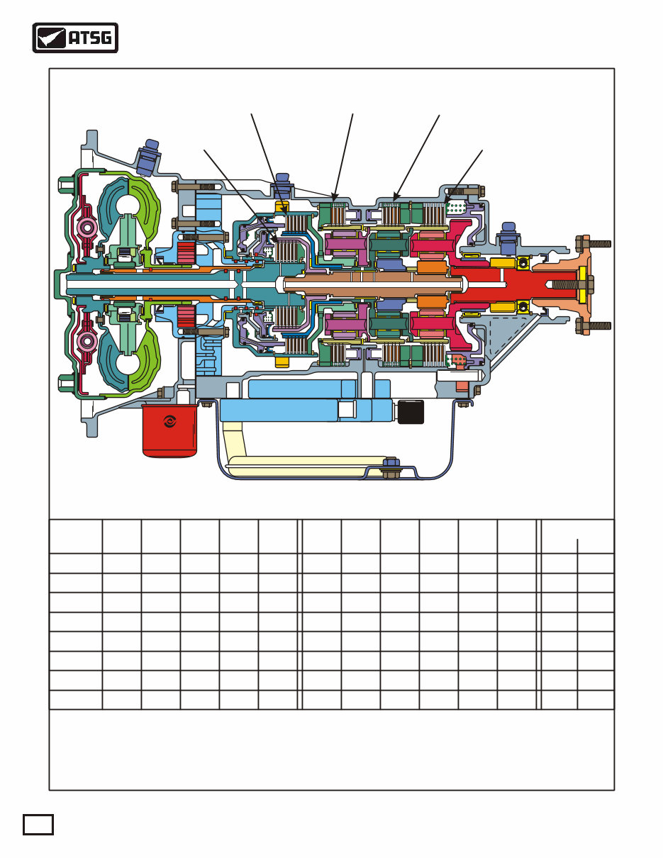
ALLISON 1000/2000 SERIES TRANSMISSION
"C5" CLUTCH
"C4" CLUTCH "C3" CLUTCH "C2" CLUTCH
"C1" CLUTCH
Figure 2
AUTOMATIC TRANSMISSION SERVICE GROUP
Technical Service Information
5
Copyright © 2000 ATSG
Allison
Transmission
Allison
Transmission Transmission
D I V I S I O N O F G E N E R A L M O T O R S C O R P .
INDIANAPOLIS, INDIANA
MODEL
UAW
933
1000 SERIES
DATE
99F21 X X
X X X X X X X X X X
X X X X X X X X X
X X - X X X X X X - X X X X
X X - X X X X X X - X X X X
X X - X X X X X X - X X X X
X X - X X X X X X - X X X X
X X - X X X X X X - X X X X
TID
SERIAL NO.
EFCN
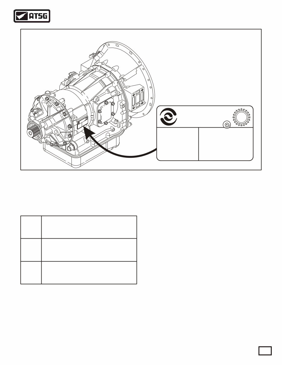
ALLISON IDENTIFICATION TAG LOCATION
TRANSMISSION IDENTIFICATION TAG
Figure 3
Several different transmission configurations are
available within the 1000/2000/2400 Series. The
different models are identified as follows:
1000
Series
2000
Series
2400
Series
Heavy-duty automatic transmission
with parking pawl.
Maximum GVW = 19850 lb.
Heavy-duty automatic transmission
with parking pawl.
Maximum GVW = 26000 lb.
Heavy-duty automatic transmission
without parking pawl.
Maximum GVW = 30000 lb.
Each transmission is identified by a model
designation, group numbers, and serial number. This
information is included on the transmission
identification tag located on the right rear side of the
transmission case, as shown in Figure 3.
This information must be used when discussing
specific service issues, or when parts replacement is
necessary. The transmission identification tag also
includes the date of manufacture, and also the
transmission identification number used with the
diagnostic systems.
Special Note:
Allison Series 1000/2000/2400 transmissions are
designed and manufactured to metric standards, and
metric tools are required for service.
The cooler ports and the main line pressure tap are
the only non-metric fittings on the transmission
case. The output flange/yoke retaining bolt is also
non-metric.
AUTOMATIC TRANSMISSION SERVICE GROUP
Technical Service Information
6
Copyright © 2000 ATSG
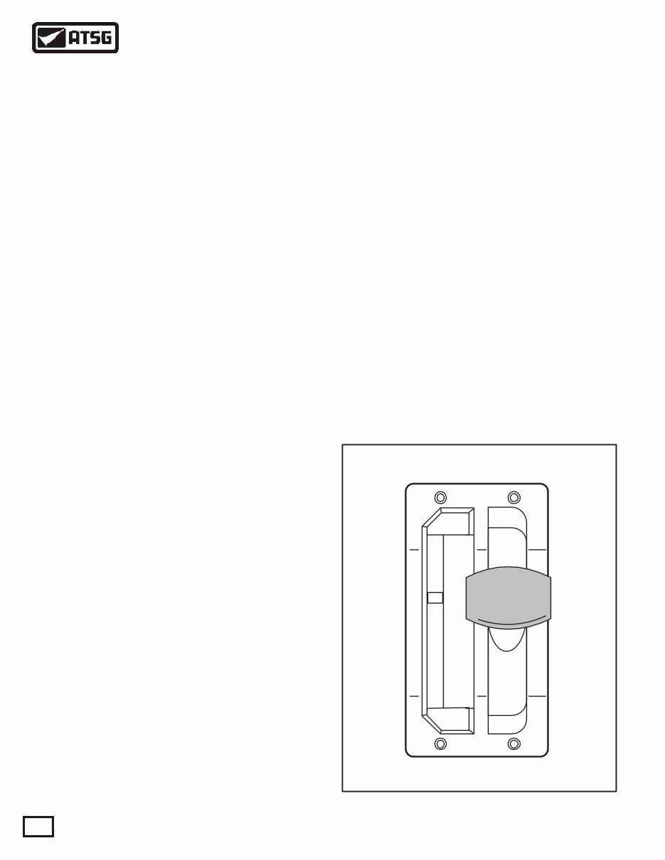
Figure 4
GENERAL DESCRIPTION AND OPERATION
TYPICAL MANUAL SHIFT TOWER
Allison 1000/2000/2400 Series transmissions are
torque converter driven fully automatic units. All
models have neutral, reverse, and up to 5 forward
speeds, with 5th gear being overdrive. Refer to
Figure 2 for the different gears ratios available in the
different models.
The torque converter housings of these units mate
directly to SAE No. 2, SAE No. 3, or direct to the
engine block in some cases. Flexplate drive is used
for all engine to transmission torque transfer.
Several different torque converters are available to
match the transmissions to a wide variety of diesel
and gasoline engines. The torque converter is a single
stage, three element unit, consisting of a pump, stator,
and turbine, with the addition of a converter clutch to
provide direct drive from the engine to the
transmission. The converter clutch is applied and
released electronically, and changes the direction of
fluid flow in the converter as in most typical
converters today.
Internally these units contain 2 rotating clutches (C1
and C2), and 3 brake clutches (C3, C4 and C5), to
direct the flow of torque through the unit. All clutch
packs are hydraulically applied and spring released,
with automatic wear compensation, and their
locations in the transmission are shown in the cut-
away in Figure 2.
The Transmission Control Module (TCM) signals
six different solenoids, located on the valve body, to
apply and release clutches based on vehicle speed and
power combinations, and the range selected by the
operator.
The planetary gear train consists of three constant
mesh, helical gear planetary sets, refered to as P1, P2,
and P3. By the engagement of the 5 clutch packs in
various combinations, the planetary gear sets react
singly or together to provide 5 forward speeds,
neutral, and reverse.
A common hydraulic system provides fluid for all
hydraulic operations, lubrication, and cooling. The
front oil pump, driven by the converter, provides the
pressure needed for the hydraulic system, and comes
from the common sump in the bottom pan.
A suction filter, located in the bottom pan provides
general protection to the entire hydraulic system, and
a spin-on filter provides full time protection for the
control solenoids and multipass protection for the
entire system.
The spin-on filter is located externally on the
converter housing at the lower left front of the
transmission.
Some 1000/2000/2400 Series transmissions are
available with an optional extension housing that
accommodates an OEM installed two shoe,
expanding type, drum parking brake.
The 1000/2000/2400 Series transmissions use lever
type shift selectors, as shown in Figure 4. The vehicle
may be equipped with one or two shift selectors,
depending on the number of operator stations for
driving the vehicle and/or operating a variety of
chassis mounted equipment. The shift positions on
the shift selector can vary according to the shift
selector installed in the vehicle.
P
R
N
D
4
2
1
DO NOT
SHIFT
DO NOT
SHIFT
NOTE: Refer to Figure 5 for the various Shift
Selector positions, and corresponding ranges that
can be attained for all 1000/2000/2400 Series
models.
AUTOMATIC TRANSMISSION SERVICE GROUP
Technical Service Information
7
Copyright © 2000 ATSG
ALL 1000 AND 2400 SERIES
ALL 2000 SERIES "WITH" AUTO-APPLY PARKING BRAKE
ALL 2000 SERIES "WITHOUT" AUTO-APPLY PARKING BRAKE
Figure 5
Shift
Selector
Position
Shift
Selector
Position
Shift
Selector
Position
Shift
Selector
Position
Shift
Selector
Position
Shift
Selector
Position
Shift
Selector
Position
Shift
Selector
Position
Shift
Selector
Position
Gears
Available
Gears
Available
Gears
Available
Gears
Available
Gears
Available
Gears
Available
Gears
Available
Gears
Available
Gears
Available
P (Park)
PB = (Park)
P (Park)
PB = (Park)
P (Park)
PB = (Park)
R (Reverse)
R (Reverse)
R (Reverse)
R (Reverse)
R (Reverse)
R (Reverse)
R (Reverse)
R (Reverse)
R (Reverse)
N (Neutral)
N (Neutral)
N (Neutral)
N (Neutral)
N (Neutral)
N (Neutral)
N (Neutral)
N (Neutral)
N (Neutral)
D (Drive)
D (Drive)
D (Drive)
D (Drive)
D (Drive)
D (Drive)
D (Drive)
D (Drive)
D (Drive)
4 (Fourth)
4 (Fourth)
4 (Fourth)
4 (Fourth)
4 (Fourth)
4 (Fourth)
3 (Third)
3 (Third)
3 (Third)
2 (Second)
2 (Second)
2 (Second)
2 (Second)
2 (Second)
2 (Second)
3 (Third)
3 (Third)
3 (Third)
1 (First)
1 (First)
1 (First)
1 (First)
1 (First)
1 (First)
1 (First)
1 (First)
1 (First)
Neutral*
Neutral*
Reverse
Reverse
Reverse
Neutral
Neutral
Neutral
1-5
1-5
1-5
1-5
1-5
1-5
1-5 (1-4)**
1-5 (1-4)**
1-5 (1-4)**
1-4
1-4
1-4
1-4
1-4
1-4
1-3
1-3
1-3
1-3
1-3
1-3
1-2
1-2
1-2
1-2
1-2
1-2
1st
1st
1st
1st
1st
1st
1st
1st
1st
Neutral
Neutral
Neutral
Neutral
Neutral
Neutral
Reverse
Reverse
Reverse
Reverse
Reverse
Reverse
Neutral*
Neutral*
Neutral*
Neutral*
* With Park Pawl Engaged
* With Auto-Apply Parking Brake Engaged
** 4 Speed Calibration or Trailering Mode
** 4 Speed Calibration or Trailering Mode
PB = Auto-Apply Parking Brake
** 4 Speed Calibration or Trailering Mode
AUTOMATIC TRANSMISSION SERVICE GROUP
Technical Service Information
8
Copyright © 2000 ATSG
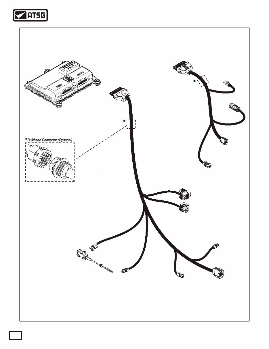
Figure 6
TYPICAL TRANSMISSION CONTROL MODULE
AND VEHICLE HARNESS
TRANSMISSION CONTROL
MODULE (TCM)
TRANSMISSION (J2)
HARNESS
VEHICLE (J1)
HARNESS
"J1"
CONNECTOR
(GRAY)
J 1939
CONNECTOR
(OPTIONAL)
VIW "X"
CONNECTOR
VIW "Y"
CONNECTOR
GP 19
CONNECTOR
NSBU SWITCH
CONNECTORS
OUTPUT
SPEED SENSOR
CONNECTOR
ENGINE
SPEED SENSOR
CONNECTOR
TURBINE
SPEED SENSOR
CONNECTOR
TPS
CONNECTOR
THROTTLE
POSITION
SENSOR (TPS)
7 PIN
4 PIN
"J2"
CONNECTOR
(RED)
Actual harness configuration may differ from this illustration.
AUTOMATIC TRANSMISSION SERVICE GROUP
Technical Service Information
9
Copyright © 2000 ATSG
ELECTRICAL OPERATION
EXTERNAL COMPONENTS
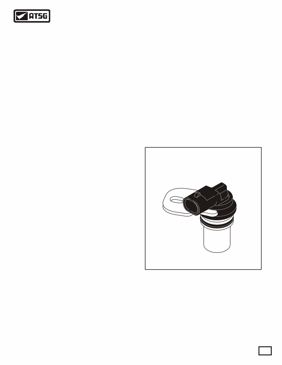
SPEED SENSORS
TYPICAL SPEED SENSOR
ENGINE SPEED SENSOR
TURBINE SPEED SENSOR
OUTPUT SPEED SENSOR
Figure 7
The electronic control of the transmission is
performed by the Transmission Control Module
(TCM). Transmissin Control Modules are available
in both 12V and 24V configurations, to match the
configuration of the vehicle electrical system.
The TCM, shown in Figure 6, recieves and processes
signals from various switches and sensors. The TCM
determines shift sequences, shift timing, and clutch
apply and release pressures. The TCM uses this
information to control solenoids and valves, supply
system status, and provide diagnostic information for
service technicians.
The speed sensors are variable reluctance devices
which convert mechanical motion to an AC voltage.
Each sensor consists of a wire coil wrapped around a
pole piece that is adjacent to a permanent magnet.
These elements are contained in a housing which is
mounted adjacent to a rotating ferrous member, such
as a gear tooth. Two signal wires extend from one end
of the housing and an exposed end of the pole piece is
at the opposite end of the housing. As a ferrous object,
such as a gear tooth approaches and passes through
the gap at the end of the pole piece, an AC voltage
pulse is induced in the wire coil. The TCM calculates
the frequency of these AC pulses and converts it to a
speed value. The AC voltage generated varies from
150mV at low speed to 15V at high speed. The signal
wires from the sensor are formed as twisted pairs to
cancel magnetically induced fields. The cable is also
shielded to protect from voltage-related fields. The
typical speed sensor is shown in Figure 7. Noise from
other sources is eliminated by using two-wire
differential inputs at the TCM.
The Engine Speed Sensor is externally mounted in
the torque converter housing, and directed at the ribs
protruding from the torque converter as shown in
Figure 1.
The Turbine Speed Sensor is externally mounted in
the main transmission case, and directed at the tone
wheel or PTO drive gear attached to the C1/C2 clutch
housing as shown in Figure 1.
The Output Speed Sensor is externally mounted in
the extension housing and directed at the teeth of a
tone wheel splined to and rotating with the output
shaft as shown in Figure 1.
AUTOMATIC TRANSMISSION SERVICE GROUP
Technical Service Information
10
Figure 8
Figure 10 Figure 9
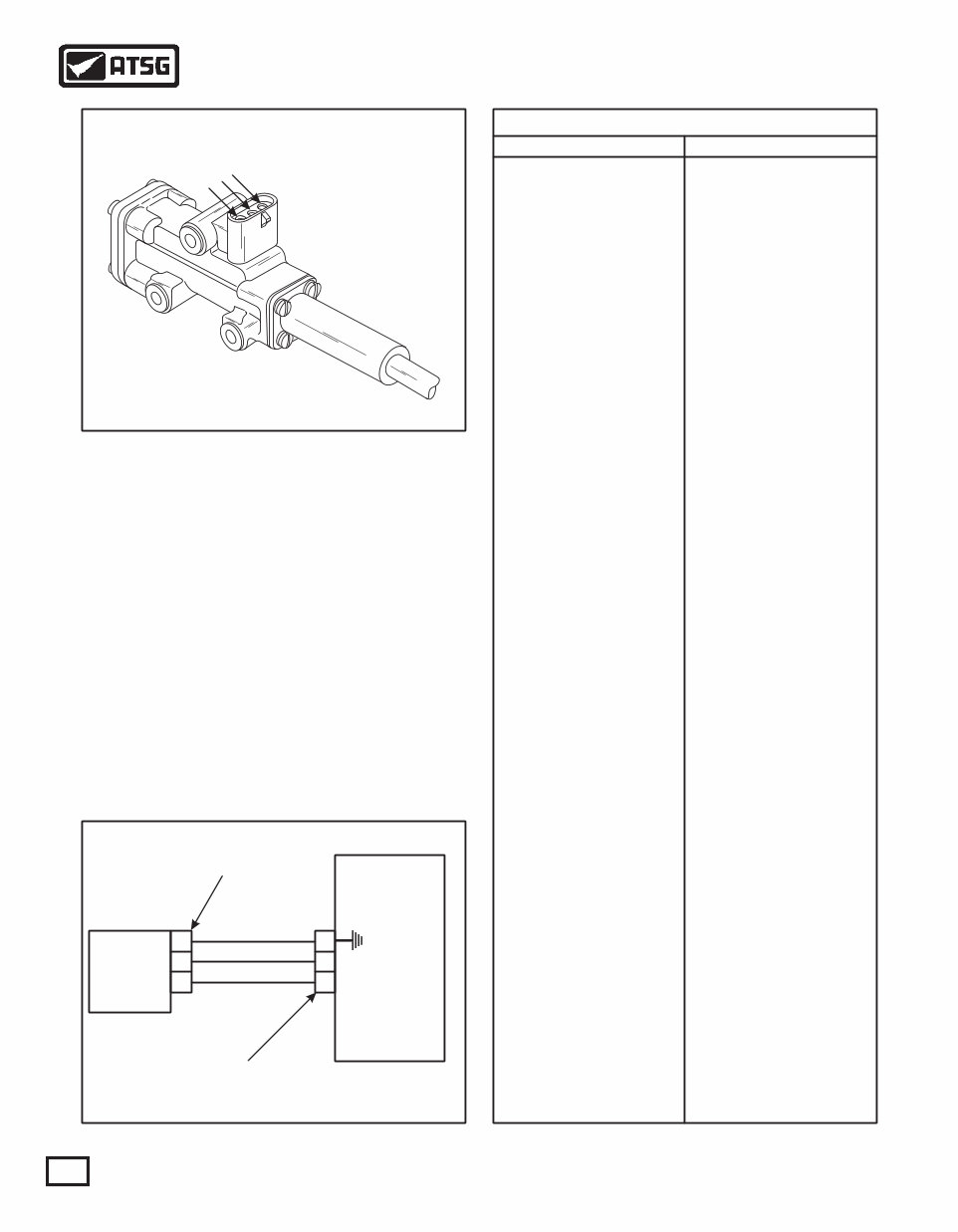
THROTTLE POSITION SENSOR
THROTTLE POSITION SENSOR
Copyright © 2000 ATSG
mm/inch
(TPS) Distance of Travel Versus Volts
0/0
1/.039"
2/.079"
3/.118"
4/.157"
5/.197"
6/.236"
7/.275"
8/.314"
9/.354"
10/.394"
11/.433"
12/.472"
13/.511"
14/.551"
15/.590"
16/.629"
17/.669"
18/.708"
19/.748"
20/.787"
21/.826"
22/.866"
23/.905"
24/.945"
25/.984"
26/1.023"
27/1.063"
28/1.102"
29/1.142"
30/1.181"
31/1.220"
32/1.260"
33/1.299"
34/1.339"
35/1.378"
36/1.417"
37/1.457"
38/1.496"
39/1.535"
40/1.575"
41/1.614"
42/1.654"
43/1.693"
44/1.732"
45/1.772"
46/1.811"
Volts
0
0.11
0.22
0.33
0.44
0.55
0.66
0.77
0.88
0.99
1.10
1.20
1.30
1.43
1.54
1.65
1.76
1.87
1.98
2.08
2.19
2.30
2.41
2.52
2.63
2.74
2.85
2.96
3.07
3.18
3.29
3.40
3.51
3.62
3.73
3.84
3.95
4.06
4.17
4.28
4.39
4.50
4.61
4.72
4.83
4.94
5.05
The Throttle Position Sensor (TPS) can be mounted to
the engine, chassis, or transmission. The TPS
contains a pull actuation cable and a potentiometer.
One end of the cable is attached to the throttle lever
and the other end, inside a protective housing, to the
potentiometer. Output voltage from the TPS is
directed to the Transmission Control Module (TCM)
through the external harness. The voltage signal will
vary and indicates the throttle position and in
combination with other input data will determine shift
timing. Refer to the chart provided in Figure 10 for
approximate voltages at various throttle openings. It
is basically the same as most current GM models with
0.5 volts at idle, to 5.0 volts at wide open throttle.
A
B
C
Transmission
Control Module
(TCM)
Throttle
Position
Sensor
(TPS)
20
9
19
A
B
C
TCM "J2" (RED)
Connector
Pink, 5V Supply
Green, Ground
Blue, Signal Ret.
TPS
Connector
You're Reading a Preview
What's Included?
Fast Download Speeds
Online & Offline Access
Access PDF Contents & Bookmarks
Full Search Facility
Print one or all pages of your manual
$31.99
Viewed 88 Times Today


Secure transaction
What's Included?
Fast Download Speeds
Online & Offline Access
Access PDF Contents & Bookmarks
Full Search Facility
Print one or all pages of your manual
$31.99
The Allison 1000 & 2000 Transmission Master Workshop Manual provides comprehensive guidance for repairing and maintaining these transmissions. Whether you're a professional mechanic or a DIY enthusiast, this manual equips you with the necessary technical information.
It comes in a file format that is compatible with all versions of Windows, Mac, and Linux. The manual is printable and can be viewed with Adobe Reader. With clear and crisp content, it is easy to understand and navigate, making it a valuable resource for anyone working with these transmissions.


