

Thermo King Diagnoses Service Manual SB 110 210 310 SLX200
What's Included?
Fast Download Speeds
Online & Offline Access
Access PDF Contents & Bookmarks
Full Search Facility
Print one or all pages of your manual

Copyright © 2006, 2007, 2008 Thermo King Corp. - Minneapolis, MN, USA
Printed in USA
DIAGNOSTIC MANUAL
SR-2 Single Temp
Microprocessor Control
System
TK 51727-2-OD Rev 1 (09/08)
Part 1 – (Sections 1-5)
Part 2 – (Sections 6-8)
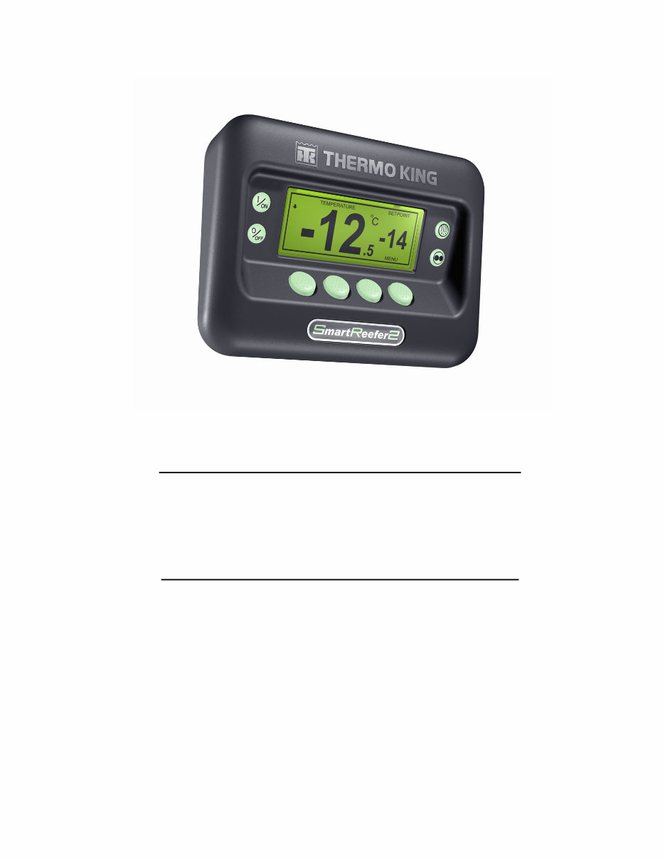
Base Controller/Interface Board Hardware Versions SR-2/A, SR-2/B and SR-2/C
HMI Control Panel Versions HMI-1 and HMI-2
and
Base Controller Software Revisions through B007
HMI Control Panel Software Revisions through 6512/6612/6712
Used on: SB-110
SB-210
SB-310
SL-400e
SLX-100
SLX-200
SLX-400

Revision History SR-2 Diagnostic Manual
Preliminary TK 51727-2-OD (Preliminary, 02/04)
Full Release TK 51727-2-OD (02/05) Base Controller B002, HMI 6502/6503
Rev 1 TK 51727-2-OD Rev 1 (09/08) Base Controller/IFB Hardware SR-2/A, SR-2/B and SR-2/C
HMI Control Panel HMI-1 and HMI-2
Base Controller Software including B007
HMI Control Panel Software including 6512
This manual is published for informational purposes only and the information so provided should not be
considered as all-inclusive or covering all contingencies. If further information is required Thermo King
Corporation should be consulted.
Sale of product shown in this manual is subject to Thermo King's terms and conditions including, but not
limited to, the THERMO KING LIMITED EXPRESS WARRANTY. Such terms and conditions are available
upon request. Thermo King's warranty will not apply to any equipment which has been "so repaired or altered
outside the manufacturer’s plants as, in the manufacturer’s judgment, to affect its stability".
No warranties express or implied, including warranties of fitness for a particular purpose or merchantability, or
warranties arising from course of dealing or usage of trade, are made regarding the information,
recommendations and descriptions contained herein. Manufacturer is not responsible and will not be held
liable in contract or in tort (including negligence) for any special, indirect or consequential damages, including
injury or damage caused to vehicles, contents or persons, by reason of the installation of any Thermo King
product or its mechanical failure.
SR-2 Hardware and Software Features
This manual covers the following SR-2 hardware revisions :
Base Controller/Interface Board Versions SR-2/A, SR-2/B and SR-2/C
and
HMI Control Panel Versions HMI-1 and HMI-2
This manual covers the following SR-2 software revisions :
Base Controller Software Revisions through B007
and
HMI Control Panel Software Revisions through 6512/6612/6712
Earlier versions of hardware and software are similar,
but may not include or support all features shown in this manual.
See Section 7 of this manual for additional details.


HOW TO USE THIS MANUAL
Because not everyone is familiar with microprocessor based control systems, please take a few minutes to
read this page. It explains the content and structure of this manual. This will make it easier for you to find the
information you need.
Section 1 - Safety information
This section contains the safety information for the SR-2 control system. Read this material carefully before
working on the unit.
Section 2 - Hardware Description
This section describes the SR-2 control system hardware. It identifies and locates controllers, relays, LED’s,
fuses and other components and provides connector maps for all connectors.
Section 3 - Software Description
This section discusses the operation of the SR-2 control system software and programmable features. Each
menu and feature is discussed individually to illustrate how they are used.
Section 4 - Operation
This section explains how to operate the SR-2 control system. This information is referenced by material in
Section 5 Diagnostics.
Section 5 - Diagnostics
This section explains how to diagnose units equipped with the SR-2 control system. It includes both Alarm
Code Diagnostics and Other Symptom Diagnostics. This section will reference material in Section 4
Operation and Section 6 Service Procedures.
Section 6 - Service Procedures
This section includes Service Procedures to assist the technician when servicing units equipped with the SR-
2 control system. These procedures are referenced by the diagnostic routines in Section 5 Diagnostics.
Section 7 - Service Information
This section offers Service Information on the basic component parts of the SR-2 control system. It includes
hardware and software history as well as interchangeability information.
Section 8 – Schematics and Wiring Diagrams
This section includes the SR-2 control system electrical schematics and unit wiring diagrams.

Control System Notes
The following procedures must be followed when working on units equipped with microprocessor based
control systems.
• Never use testers consisting of a battery and a light bulb to test circuits on any microprocessor based
equipment.
• The unit must be turned off before connecting or disconnecting the battery.
• Any time a graded sensor is replaced it must be calibrated as shown in Service Procedure A15A
Temperature Sensor Grade Calibration.
• Any time the Base Controller is replaced, these Service Procedures must be used:
A02A Recording Existing Programmable Feature Settings
A03A Replacement of the Base Controller or Interface Board
A04A Programmable Feature Setup
• Any time the Interface Board is replaced, Service Procedure A03A Replacement of the Base
Controller or Interface Board must be followed.
• Any time welding is to be done on the unit or vehicle Service Procedure A26A Welding on Units
Equipped with Microprocessors must be followed.


Section 1 – SR-2 Safety Information
1-1
27 August 2008
TABLE OF CONTENTS - SECTION 1
General Practices .................................................................................................................................................... 3
Auto Start/Stop ........................................................................................................................................................ 3
Refrigerant................................................................................................................................................................ 4
Refrigerant First Aid ............................................................................................................................................. 4
Refrigeration Oil....................................................................................................................................................... 4
Refrigeration Oil First Aid ..................................................................................................................................... 4
Electrical Considerations ....................................................................................................................................... 5
Base Controller Service........................................................................................................................................ 5
Welding................................................................................................................................................................. 5
Electrical Hazards.................................................................................................................................................... 5
High Voltage ......................................................................................................................................................... 5
High Voltage First Aid........................................................................................................................................... 5
Low Voltage .......................................................................................................................................................... 6

Section 1 – SR-2 Safety Information
1-2
27 August 2008

Section 1 – SR-2 Safety Information
1-3
27 August 2008
GENERAL PRACTICES
1. Always wear goggles or safety glasses.
Refrigerant and battery acid can permanently
damage the eyes.
2. Never close the compressor discharge service
valve when the unit is running. Never operate
the unit with the discharge service valve closed.
3. Keep hands, clothing and tools clear of fans and
belts when the unit is running.
4. Be sure gauge manifold hoses are in good
condition. Never let them come in contact with
belts, fans, pulleys or hot surfaces.
5. Never apply heat to a sealed refrigeration
system or container.
6. Refrigerants in the presence of an open flame
produce toxic gases. These gases are severe
respiratory irritants capable of causing death.
7. Be sure all mounting bolts are the correct length
for the application and are securely tightened.
8. Use extreme caution when drilling holes in the
unit. Holes may weaken structural components.
Holes drilled into wiring can cause fire or
explosion. Holes drilled into the refrigeration
system will release refrigerant.
9. Use caution when working around exposed coil
fins. These fins can cause painful lacerations.
10. Use caution when working with refrigerant in a
closed or confined area with a limited air supply
such as a trailer, truck, container or hold of a
ship. Refrigerant tends to displace air and can
cause oxygen depletion. This may result in
unconsciousness or death due to suffocation.
AUTO START/STOP
CAUTION:
The unit can start and run automatically any
time the unit is turned on. Units start
automatically in both Cycle Sentry mode
and Continuous mode. Be sure to turn the
unit Microprocessor On/Off switch Off
before opening doors, doing inspections or
working on any part of the unit.
SR-2 units may have options that allow for
remote starting from a fully off state. Be
sure to turn the unit Microprocessor On/Off
Switch Off before opening doors, doing
inspections or working on any part of the
unit.
Some SR-2 electronic components are
connected directly to un-switched battery
power. All connections and circuits labeled
with a “2” prefix are directly connected to
battery power. Always disconnect the unit
starting battery before servicing the unit.
You're Reading a Preview
What's Included?
Fast Download Speeds
Online & Offline Access
Access PDF Contents & Bookmarks
Full Search Facility
Print one or all pages of your manual
$39.99
Viewed 28 Times Today


Secure transaction
What's Included?
Fast Download Speeds
Online & Offline Access
Access PDF Contents & Bookmarks
Full Search Facility
Print one or all pages of your manual
$39.99
Comprehensive Diagnostic Resource for the SR-2 Single Temp Microprocessor Control System
This manual is divided into two detailed sections:
- Part 1: Covers Sections 1-5
- Part 2: Covers Sections 6-8
It is applicable for the following hardware and control panel versions:
- Base Controller/Interface Board Hardware Versions: SR-2/A, SR-2/B, and SR-2/C
- HMI Control Panel Versions: HMI-1 and HMI-2
The content also includes crucial updates, covering:
- Base Controller Software Revisions through B007
- HMI Control Panel Software Revisions through 6512/6612/6712
This manual is designed for use with the following systems:
- SB-110, SB-210, SB-310, SL-400e, SLX-100, SLX-200, and SLX-400
Key Features:
- In-depth troubleshooting support: Detailed wiring diagrams and comprehensive diagnostic information.
- Practical guide for DIY repair enthusiasts: Essential information for troubleshooting and repairing the SR-2 system.
- Valuable resource for professional use: A complete reference with 685 pages covering all critical areas.
This resource is an essential addition to any DIY repair or professional toolkit for addressing issues with the SR-2 system.


