Cav Rotodiesel DPA Pumps Service Test Data
What's Included?
Fast Download Speeds
Online & Offline Access
Access PDF Contents & Bookmarks
Full Search Facility
Print one or all pages of your manual
Explanatory Notes
CAV Roto Diesel
DPA Pump Test Data
THIS PUBLICATION DIRECTLY SUPERSEDES
PUBLICATION LEX 3750. ANY REFERENCE IN ANY
OTHER PUBLICATION TO LEX 3750 MUST
THEREFORE BE TAKEN AS REFERRING TO THIS
PUBLICATION.
PUBLISHED BY SERVICE PUBLICATIONS DEPARTMENT
CAV PARTS and SERVICE
©1983 Lucas CAV Limited
ALL RIGHTS RESERVED
EXPLANATORY NOTES
0 COPYRIGHT 1983
1 of 9
CAV
LONDON W3 7SS
ROTO DIESEL DPA — SERVICE TEST PLANS
Issue I
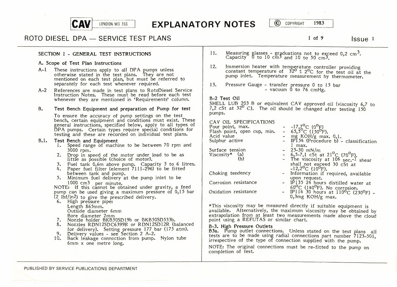
SECTION 1 - GENERAL TEST INSTRUCTIONS
A. Scope of Test Plan Instructions
A-1 These instructions apply to all DPA pumps unless
otherwise stated in the test plans. They are not
mentioned on each test plan, but must be referred to
separately for each test whenever required.
A-2 References are made in test plans to RotoDiesel Service
Instruction Notes. These must be read before each test
whenever they are mentioned in 'Requirement& column.
B. Test Bench Equipment and preparation of Pump for test
To ensure the accuracy of pump settings on the test
bench, certain equipment and conditions must exist. These
general instructions, specified below, apply to all types of
DPA pumps. Certain types require special conditions for
testing and these are recorded on individual test plans.
B.1. Test Bench and Equipment
1. Speed range of machine to be between 70 rpm and
3000 rpm.
2. Drop in speed of the motor under load to be as
little as possible (choice of motor).
3. Fuel tank 0,6m above pump. Capacity 5 to 6 litres.
4. Paper fuel filter (element 7111-296) to be fitted
between tank and pump.
.5. Minimum fuel delivery at the pump inlet to be
1000 cm3 per minute.
NOTE: If this cannot be obtained under gravity, a feed
pump can be used giving a maximum pressure of 0,15 bar
(2 lbf/in2) to give the prescribed delivery.
6. High pressure pipe:
Length 865m m.
Outside diameter 6mm
Bore diameter 2mm
7. Nozzle holder BKB5OSD19b or BKB5OSD533b.
8. Nozzles RDN12SDC6399R or RDN12SD12R (balanced
for delivery). Setting pressure 177 bar (175 atm).
9. Delivery values - see Section 2 A-2.
10. Back leakage connection from pump. Nylon tube
6mm x one metre long.
11. Measuring glasses - grOuations not to exceed 0,2 cm
3 .
Capacity 0 to 10 cm- 5 and 10 to 50 cm 3 .
12. Immersion heater with temperature controller providing
constant temperature of 32
0
± 2 ° C for the test oil at the
pump inlet. Temperature measurement by thermometer.
13. Pressure Gauge - transfer pressure 0 to 15 bar
- vacuum 0 to 76 cmHg.
B-2 Test 011
SHELL LUB 203 B or equivalent CAV approved oil (viscosity 6,7 to
7,2 cSt at 32 °
C). The oil should be changed after testing 150
pumps.
-17,7, 0 C (0 ° F)
- 65,5 - C (150 ° F).
- mg KOH/g max. 0,1.
- IP154 (Procedure b) - classification
1 max.
- 25-30 mN/rn
- 6,5-7,1 cSt at 21 ° C (70 F).
The viscosity at 106 sec.
-1 shear
h u a , 11 20 7 t e o x o c F e ). e d 30 cSt at
- Information if required, available
upon request.
IP135 24 hours distilled water at
60 ° C (140 ° F). No corrosion.
_ IP114 30 hours at 110°C (230
° F) -
0,3mg KOH/g max.
*This viscosity may be measured directly if suitable equipment is
available. Alternatively, the maximum viscosity may be obtained by
extrapolation from at least two measurements made above the cloud
point using a REFUTAS or similar chart.
B-3. High Pressure Outlets
B3a. Rump outlet connections. Unless stated on the test plans all
tests are to be made using radial connections part number 7123-501,
irrespective of the type of connection supplied with the pump.
NOTE: The original connections must be re-fitted to the pump on
completion of test.
CAV OIL SPECIFICATIONS
Pour point, max.
Flash point, open cup, min.
Acid value
Sulphur active
Surface tension
Viscosity* (a)
(b)
Choking tendency
Corrosion resistance
Oxidation resistance
PUBLISHED BY SERVICE PUBLICATIONS DEPARTMENT
EXPLANATORY NOTES
0 COPYRIGHT
1983
2 of 9
CAV
LONDON W3 7SS
ROTO DIESEL DPA — SERVICE TEST PLANS
Issue
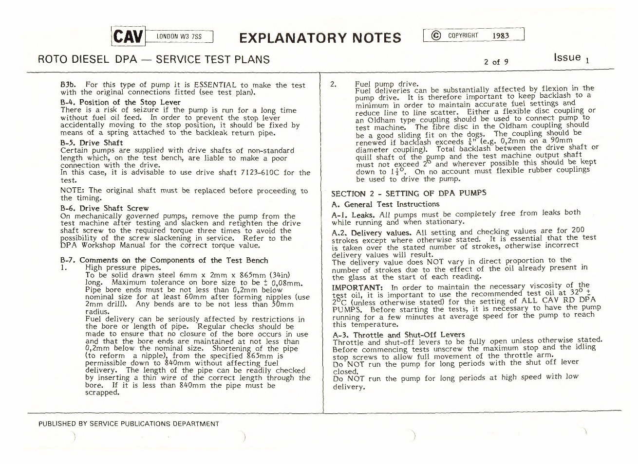
B3b. For this type of pump it is ESSENTIAL to make the test
with the original connections fitted (see test plan).
B-4. Position of the Stop Lever
There is a risk of seizure if the pump is run for a long time
without fuel oil feed. In order to prevent the stop lever
accidentally moving to the stop position, it should be fixed by
means of a spring attached to the backleak return pipe.
B-5. Drive Shaft
Certain pumps are supplied with drive shafts of non-standard
length which, on the test bench, are liable to make a poor
connection with the drive.
In this case, it is advisable to use drive shaft 7123-610C for the
test.
NOTE: The original shaft must be replaced before proceeding to
the timing.
B-6. Drive Shaft Screw
On mechanically governed pumps, remove the pump from the
test machine after testing and slacken and retighten the drive
shaft screw to the required torque three times to avoid the
possibility of the screw slackening in service. Refer to the
DPA Workshop Manual for the correct torque value.
B-7. Comments on the Components of the Test Bench
1. High pressure pipes.
To be solid drawn steel 6mm x 2mm x 865mm (34in)
long. Maximum tolerance on bore size to be IF: 0,08mm.
Pipe bore ends must be not less than 0,2mm below
nominal size for at least 60mm after forming nipples (use
2mm drill). Any bends are to be not less than 50mm
radius.
Fuel delivery can be seriously affected by restrictions in
the bore or length of pipe. Regular checks should be
made to ensure that no closure of the bore occurs in use
and that the bore ends are maintained at not less than
0,2mm below the nominal size. Shortening of the pipe
(to reform a nipple), from the specified 865mm is
permissible down to 840mm without affecting fuel
delivery. The length of the pipe can be readily checked
by inserting a thin wire of the correct length through the
bore. If it is less than 840mm the pipe must be
scrapped.
2. Fuel pump drive.
Fuel deliveries can be substantially affected by flexion in the
pump drive. It is therefore important to keep backlash to a
minimum in order to maintain accurate fuel settings and
reduce line to line scatter. Either a flexible disc coupling or
an Oldham type coupling should be used to connect pump to
test machine. The fibre disc in the Oldham coupling should
be a good sliding fit on the dogs. The coupling should be
renewed if backlash exceeds TI
.-" (e.g. 0,2mm on a 90mm
diameter coupling). Total backlash between the drive shaft or
quill shaft of the Rump and the test machine output shaft
must not exceed 2 and wherever possible this should be kept
down to 14 °
. On no account must flexible rubber couplings
be used to drive the pump.
SECTION 2 - SETTING OF DPA PUMPS
A. General Test Instructions
A-1. Leaks.
All pumps must be completely free from leaks both
while running and when stationary.
A.2. Delivery values.
All setting and checking values are for 200
strokes except where otherwise stated. It is essential that the test
is taken over the stated number of strokes, otherwise incorrect
delivery values will result.
The delivery value does NOT vary in direct proportion to the
number of strokes due to the effect of the oil already present in
the glass at the start of each reading.
IMPORTANT:
In order to maintain the necessary viscosity of the
tst oil, it is important to use the recommended test oil at 32
0
t
2'C (unless otherwise stated) for the setting of ALL CAV RD DP A
PUMPS. Before starting the tests, it is necessary to have the pump
running for a few minutes at average speed for the pump to reach
this temperature.
A-3. Throttle and Shut-Off Levers
Throttle and shut-off levers to be fully open unless otherwise stated.
Before commencing tests unscrew the maximum stop and the idling
stop screws to allow full movement of the throttle arm.
Do NOT run the pump for long periods with the shut off lever
closed.
Do NOT run the pump for long periods at high speed with low
delivery.
PUBLISHED BY SERVICE PUBLICATIONS DEPARTMENT
CAV
LONDON W3 7SS
EXPLANATORY NOTES
0 COPYRIGHT
1983
3 of 9
ROTO DIESEL DPA — SERVICE TEST PLANS
Issue
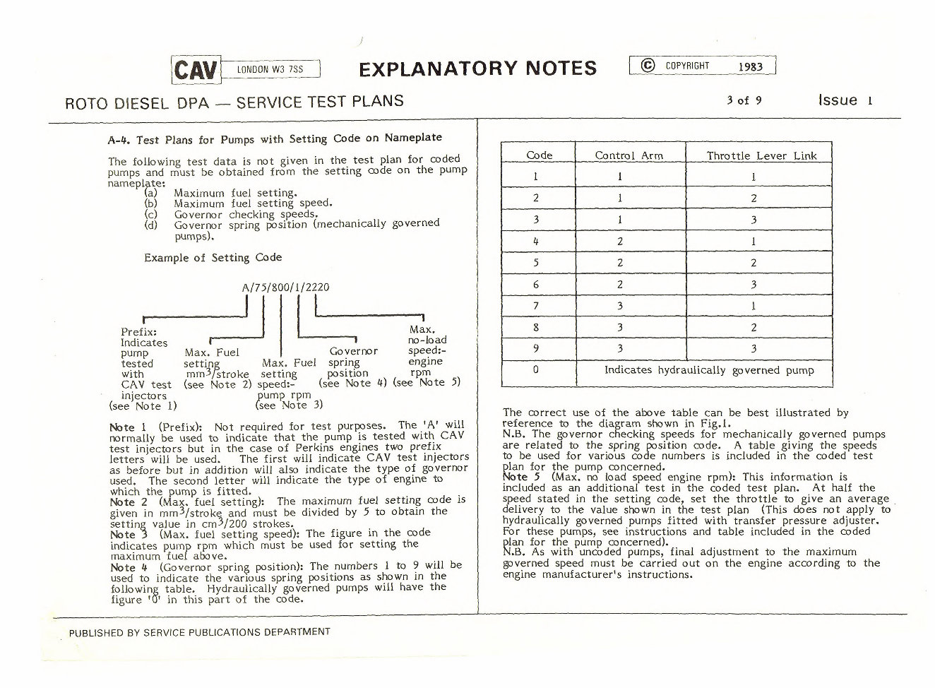
A-4. Test Plans for Pumps with Setting Code on Nameplate
The following test data is not given in the test plan for coded
pumps and must be obtained from the setting code on the pump
nameplate:
(a) Maximum fuel setting.
(b)
Maximum fuel setting speed.
(c) Governor checking speeds.
(d)
Governor spring position (mechanically governed
pumps).
Example of Setting Code
Prefix:
Indicates
Max.
no-load
pump Max. Fuel
Governor speed:-
tested setting Max. Fuel spring engine
with mm 3 /stroke setting position
rpm
CAV test (see Note 2) speed:-
(see Note 4) (see Note 5)
injectors rpm ,pump
(see Note 1) (see Note 3)
Note 1
(Prefix): Not required for test purposes. The 'A' will
normally be used to indicate that the pump is tested with CAV
test injectors but in the case of Perkins engines two prefix
letters will be used
The first will indicate CAV test injectors
as before but in addition will also indicate the type of governor
used. The second letter will indicate the type of engine to
which the pump is fitted.
Note 2
(Max. fuel setting): The maximum fuel setting code is
given in mm 3 /stroke and must be divided by 5 to obtain the
setting value in cm 3 /200 strokes.
Note 3 (Max. fuel setting speed): The figure in the code
indicates pump rpm which must be used for setting the
maximum fuel above.
Note 4
(Governor spring position): The numbers 1 to 9 will be
used to indicate the various spring positions as shown in the
following table. Hydraulically governed pumps will have the
figure '0' in this part of the code.
Code Control Arm Throttle Lever Link
1 1 1
2 1 2
3 1 3
4 2 1
5 2 2
6 2 3
7 3 1
8 3 2
9 3 3
0 Indicates hydraulically governed pump
The correct use of the above table can be best illustrated by
reference to the diagram shown in Fig.l.
N.B. The governor checking speeds for mechanically governed pumps
are related to the spring position code. A table giving the speeds
to be used for various code numbers is included in the coded test
plan for the pump concerned.
Note 5 (Max. no load speed engine rpm): This information is
included as an additional test in the coded test plan. At half the
speed stated in the setting code, set the throttle to give an average
delivery to the value shown in the test plan (This does not apply to
hydraulically governed pumps fitted with transfer pressure adjuster.
For these pumps, see instructions and table included in the coded
-plan for the pump concerned).
N.B. As with uncoded pumps, final adjustment to the maximum
governed speed must be carried out on the engine according to the
engine manufacturer's instructions.
A/75/800/1/2220
I
PUBLISHED BY SERVICE PUBLICATIONS DEPARTMENT
IDLING THROTTLE
SPRING SHAFT
1 2
GUIDE GOVERNOR LINK
SPRING
WPM' )
2 t
t
GOVERNOR
ARM
3
23
4 5 6
- 7 8 9
CODE
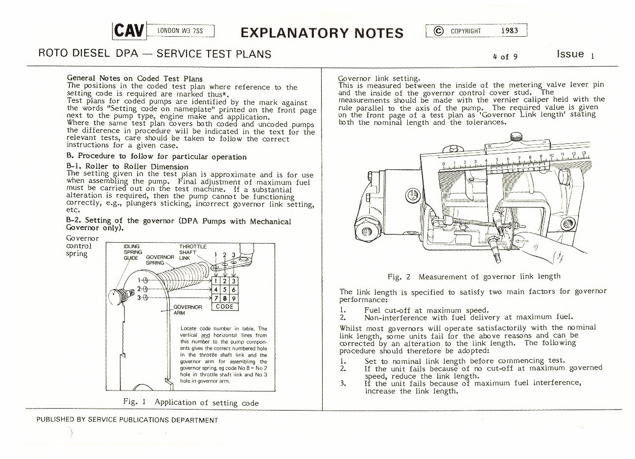
Locate code number in table. The
vertical and horizontal lines from
this number to the pump compon-
ents gives the correct numbered hole
in the throttle shaft link and the
governor arm for assembling the
governor spring, eg code No 8 = No 2
hole in throttle shaft link and No 3
hole in governor arm.
General Notes on Coded Test Plans
The positions in the coded test plan where reference to the
setting code is required are marked thus*.
Test plans for coded pumps are identified by the mark against
the words "Setting code on nameplate" printed on the front page
next to the pump type, engine make and application.
Where the same test plan covers both coded and uncoded pumps
the difference in procedure will be indicated in the text for the
relevant tests, care should be taken to follow the correct
instructions for a given case.
B. Procedure to follow for particular operation
B-1. Roller to Roller Dimension
The setting given in the test plan is approximate and is for use
when assembling the pump. Final adjustment of maximum fuel
must be carried out on the test machine. If a substantial
alteration is required, then the pump cannot be functioning
correctly, e.g., plungers sticking, incorrect governor link setting,
etc.
B-2.
Setting of the governor (DPA Pumps with Mechanical
Governor only).
Governor
control
Spring
Fig. 1 Application of setting code
Governor link setting.
This is measured between the inside of the metering valve lever pin
and the inside of the governor control cover stud. The
measurements should be made with the vernier caliper held with the
rule parallel to the axis of the pump. The required value is given
on the front page of a test plan as 'Governor Link length' stating
both the nominal length and the tolerances.
Fig. 2 Measurement of governor link length
The link length is specified to satisfy two main factors for governor
performance:
1. Fuel cut-off at maximum speed.
2. Non-interference with fuel delivery at maximum fuel.
Whilst most governors will operate satisfactorily with the nominal
link length, some units fail for the above reasons and can be
corrected by an alteration to the link length. The following
procedure should therefore be adopted:
1. Set to nominal link length before commencing test.
2. If the unit fails because of no cut-off at maximum governed
speed, reduce the link length.
3. If the unit fails because of maximum fuel interference,
increase the link length.
CAV
LONDON W3 7SS
EXPLANATORY NOTES
ROTO DIESEL DPA — SERVICE TEST PLANS
0 COPYRIGHT 1983
4 of 9
Issue
PUBLISHED BY SERVICE PUBLICATIONS DEPARTMENT
Spring Linkage
Retainer Spring
Linkage Hook
2
--.1 r•-
7mm
EXPLANATORY NOTES
© COPYRIGHT 1983
5 of 9
CAV
LONDON W3 7SS
ROTO DIESEL DPA — SERVICE TEST PLANS Issue 1
Note, however, that incorrectly machined, worn or wrongly
assembled parts can produce the same faults, and alteration to
link length, which may be correct, will not necessarily effect a
solution. Should adjustment to the link setting fail to correct
the fault, then the link should be reset to the nominal length
and the cause looked for elsewhere. Where adjustments to the
governor link length have been made, the sequence of governor
setting must be repeated and the test requirements satisfied.
Adjustments must NOT be made beyond the specified tolerance.
NOTE: For certain applications, the above procedure is only a
PRE-SETTING. In this case the test plan refers to WSN RD44
(reproduced below) which indicates the procedure to follow in
order to obtain a much more accurate setting based on the
'Hydraulic Stop'
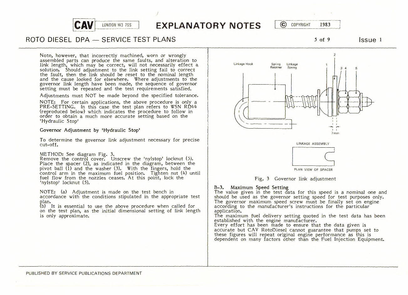
Governor Adjustment by 'Hydraulic Stop'
To determine the governor link adjustment necessary for precise
cut-off.
METHOD: See diagram Fig. 3.
Remove the control cover. Unscrew the 'nylstop' locknut (5).
Place the spacer (2), as indicated in the diagram, between the
pivot ball (1) and the washer (3). With the fingers, hold the
control arm in the maximum fuel position. Tighten nut (4) until
fuel flow from the nozzles ceases. At this point, lock the
'nylstop' locknut (5).
NOTE: (a) Adjustment is made on the test bench in
accordance with the conditions stipulated in the appropriate test
plan.
(b) It is essential to use the above procedure when called for
on the test plan, as the initial dimensional setting of link length
is only approximate.
LINKAGE ASSEMBLY
PLAN VIEW OF SPACER
Fig. 3 Governor link adjustment
B-3. Maximum Speed Setting
The value given in the test data for this speed is a nominal one and
should be used as the governor setting speed for test purposes only.
The governor maximum speed screw must be finally set on engine
according to the manufacturer's instructions for the particular
application.
The maximum fuel delivery setting quoted in the test data has been
established with the engine manufacturer.
Every effort has been made to ensure that the data given is
accurate but CAV RotoDiesel cannot guarantee that pumps set to
these figures will repeat original engine performance as this is
dependent on many factors other than the Fuel Injection Equipment.
PUBLISHED BY SERVICE PUBLICATIONS DEPARTMENT
CAI/1
LONDON W3 7SS
EXPLANATORY NOTES
0 COPYRIGHT 1983
6 of 9
ROTO DIESEL DPA — SERVICE TEST PLANS
Issue
B-4. Vacuum Test
It will sometimes be found that, due to the flexible pipe
connecting the vacuum gauge to the pump being partially filled
with air, an incorrect reading will result. To correct this,
slacken the pipe connection at the gauge end with the fuel
supply turned on. Wait until fuel flows from this pipe then re-
tighten the union.
C.
Precautions to be taken when testing the pump on the
test bench.
C-1. Fitting the Pump on the Test Bench
Under the nuts to secure the pump to the test bench use the
Spacers 9003-310B fitted on the pump originally. These have
the correct bearing surface and avoid marking the faces of the
pump housing flange.
C-2. Priming and Venting
Correct consistent operation of the auto advance is dependent
upon the exclusion of air from the auto-advance housing. This
may be sometimes improved by the removal of the advance
gauge before priming. Venting itself should be carried out at
the vent screws whilst running the pump at 100 rpm.
C-2a Pumps with Hydraulic Governor and Combined Automatic
Speed and Light Load Advance.
Besides the information given in paragraph C-2 operate the
throttle lever, press inwards and release the advance indicator
pin several times to ensure venting.
NOTE: This must be repeated after each adjustment of the
auto-advance.
C-3. Measuring the Deliveries
Where marked thus use 30 seconds glass draining time and
allow fuel to settle for 15 seconds before taking reading.
C-3a Maximum Delivery Setting for DPA Four Plunger Pumps
Four Plunger DPA pumps use a different system of maximum
fuel setting from that of the standard DPA pump. The
Camring, assembled Rollers and Shoes and adjustable type Check
Plates are dimensionally inter-related in order to achieve the
desired maximum fuel setting.
Any Check Plate Kit will give an adjustment of approximately
8mm-5 /Stroke (1,6cc/ 200 strokes) for a given maximum fuel setting,
when the top Check Plate is moved from the minimum to the
maximum position. To obtain further adjustment it is necessary to
fit a different Check Plate Kit. Each Ch_eck Plate Kit will also
give an adjustment of approximately 8mm- 5 /stroke (1,6cc/200 strokes)
and can be identified by advancing one letter in the Alphabet for
up-fuelling and retreating for down-fuelling.
EXAMPLE:
UP-FUELLING
7167-747AA
7167-747BA
DOWN-FUELLING
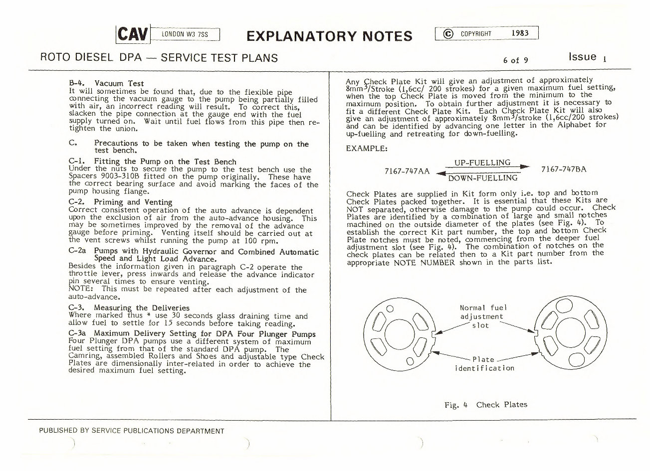
Check Plates are supplied in Kit form only i.e. top and bottom
Check Plates packed together. It is essential that these Kits are
NOT separated, otherwise damage to the pump could occur. Check
Plates are identified by a combination of large and small notches
machined on the outside diameter of the plates (see Fig. 4). To
establish the correct Kit part number, the top and bottom Check
Plate notches must be noted, commencing from the deeper fuel
adjustment slot (see Fig. 4). The combination of notches on the
check plates can be related then to a Kit part number from the
appropriate NOTE NUMBER shown in the parts list.
Normal fuel
adjustment
slot
Plate
i dent i f icat ion
Fig. 4 Check Plates
PUBLISHED BY SERVICE PUBLICATIONS DEPARTMENT
CAV
LONDON W3 7SS
EXPLANATORY NOTES
0 COPYRIGHT
1983
7 of 9
ROTO DIESEL DPA — SERVICE TEST PLANS
Issue
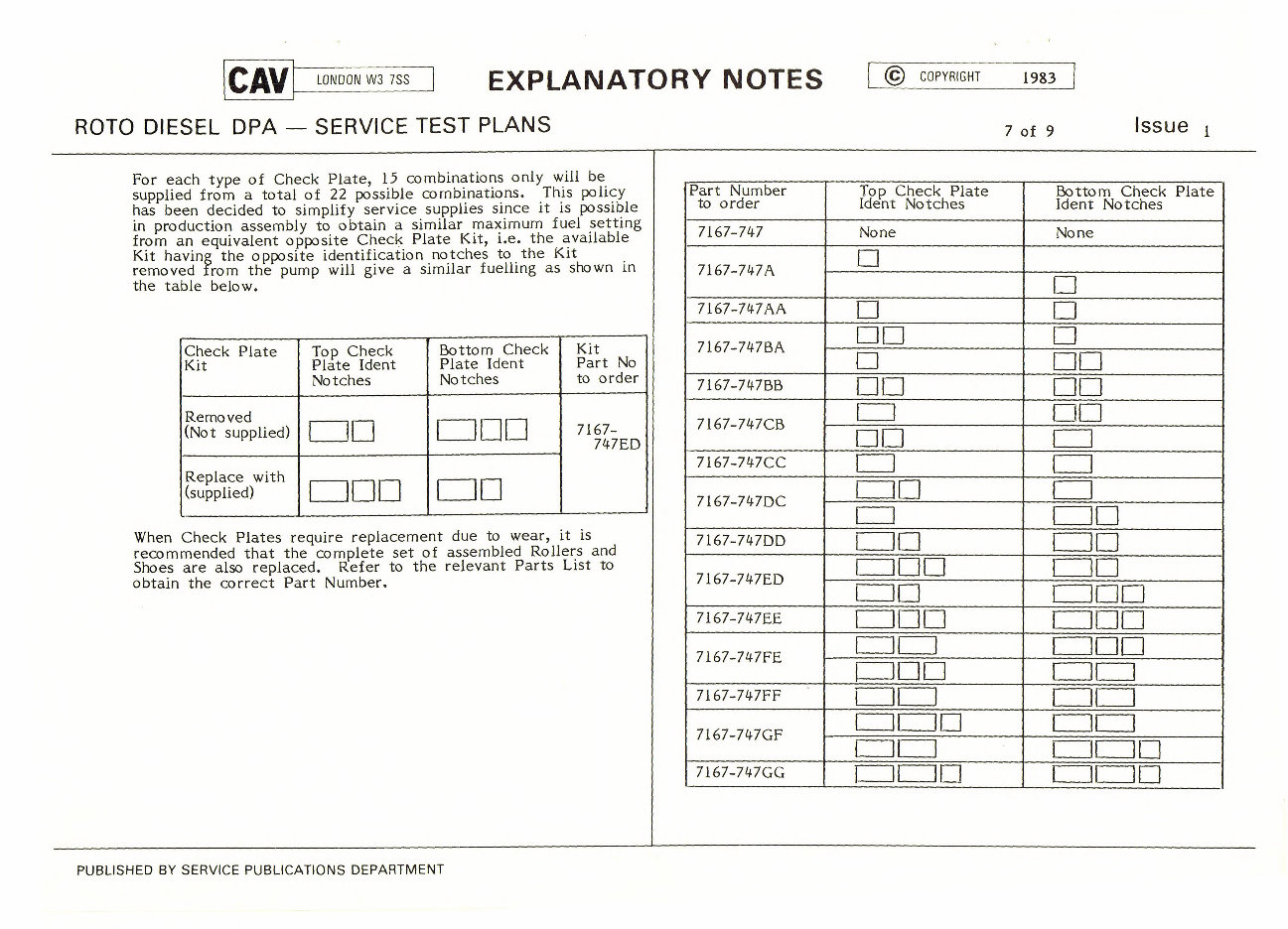
For each type of Check Plate, 15 combinations only will be
supplied from a total of 22 possible combinations. This policy
has been decided to simplify service supplies since it is possible
in production assembly to obtain a similar maximum fuel setting
from an equivalent opposite Check Plate Kit, i.e. the available
Kit having the opposite identification notches to the Kit
removed from the pump will give a similar fuelling as shown in
the table below.
Check Plate
Kit
Top Check
Plate !dent
Notches
Bottom Check
Plate Ident
Notches
Kit
Part No
to order
Removed
(Not supplied)
1- 11 11 1
7167-
747ED
I
Replace with
(supplied)
I II I I IL I
When Check Plates require replacement due to wear, it is
recommended that the complete set of assembled Rollers and
Shoes are also replaced. Refer to the relevant Parts List to
obtain the correct Part Number.
Part Number
to order
Top Check Plate
Ident Notches
Bottom Check Plate
Ident Notches
7167-747 None None
7167-747A
I
I
7167-747AA
1 1 I
7167-747BA
II I I
I II I
7167-747BB
1 11 1 I 11 1
7167-747CB
1 I I
R I
7167-747CC
I I
7167-747DC
11 1 1
1 If I
7167-747DD
III
II I
7167-747ED
11 11 1 11 1
II I I II I
7I67-747EE
1 11-11 I 11 II 1
7167-747FE
I 11 1 11 It 1
I II 11 11 1
7167-747FF
11 I I 1
I II II 1 1i i
7167-747GF
I I II In
7167-747GG
LJI R I LJI II I
PUBLISHED BY SERVICE PUBLICATIONS DEPARTMENT
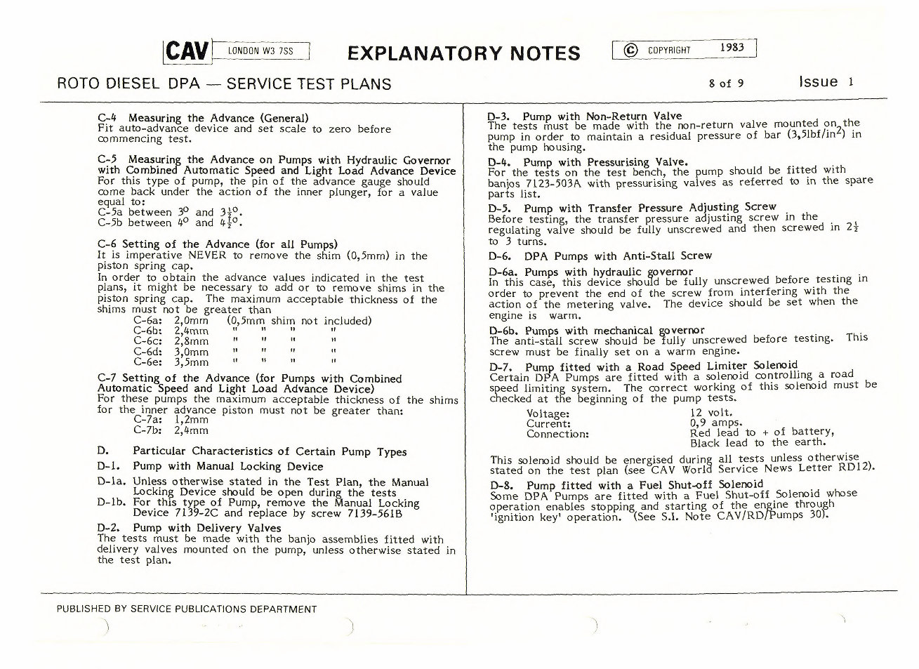
C-4 Measuring the Advance (General)
Fit auto-advance device and set scale to zero before
commencing test.
C-5 Measuring the Advance on Pumps with Hydraulic Governor
with Combined Automatic Speed and Light Load Advance Device
For this type of pump, the pin of the advance gauge should
come back under the action of the inner plunger, for a value
equal to:
C-5a between 3° and 3 1 z °
C-5b between 4
0
and 4-1°.
C-6 Setting of the Advance (for all Pumps)
It is imperative NEVER to remove the shim (0,5mm) in the
piston spring cap.
In order to obtain the advance values indicated in the test
plans, it might be necessary to add or to remove shims in the
piston spring cap. The maximum acceptable thickness of the
shims must not be greater than
C-6a: 2,0mm (0,5mm shim not included)
C-6b: 2,4mm
C-6c: 2,8mm
C-6d: 3,0mm
C-6e: 3,5mm
C-7 Setting of the Advance (for Pumps with Combined
Automatic Speed and Light Load Advance Device)
For these pumps the maximum acceptable thickness of the shims
for the inner advance piston must not be greater than:
C-7a: 1,2mm
C-7b: 2,4mm
D.
Particular Characteristics of Certain Pump Types
D-1. Pump with Manual Locking Device
0-la. Unless otherwise stated in the Test Plan, the Manual
Locking Device should be open during the tests
D-lb. For this type of Pump, remove the Manual Locking
Device 7139-2C and replace by screw 7139-561B
D-2. Pump with Delivery Valves
The tests must be made with the banjo assemblies fitted with
delivery valves mounted on the pump, unless otherwise stated in
the test plan.
D-3. Pump with Non-Return Valve
The tests must be made with the non-return valve mounted on the
pump in order to maintain a residual pressure of bar (3,51bf/inh) in
the pump housing.
0-4. Pump with Pressurising Valve.
For the tests on the test bench, the pump should be fitted with
banjos 7123-503A with pressurising valves as referred to in the spare
parts list.
D-5. Pump with Transfer Pressure Adjusting Screw
Before testing, the transfer pressure adjusting screw in the
regulating valve should be fully unscrewed and then screwed in 21
to 3 turns.
D-6. DPA Pumps with Anti-Stall Screw
D-6a. Pumps with hydraulic governor
In this case, this device should be fully unscrewed before testing in
order to prevent the end of the screw from interfering with the
action of the metering valve. The device should be set when the
engine is warm.
D-6b. Pumps with mechanical governor
The anti-stall screw should be fully unscrewed before testing. This
screw must be finally set on a warm engine.
D-7. Pump fitted with a Road Speed Limiter Solenoid
Certain DPA Pumps are fitted with a solenoid controlling a road
speed limiting system. The correct working of this solenoid must be
checked at the beginning of the pump tests.
Voltage:
12 volt.
Current: 0,9 amps.
Connection:
Red lead to + of battery,
Black lead to the earth.
This solenoid should be energised during all tests unless otherwise
stated on the test plan (see CAV World Service News Letter RD12).
0-8. Pump fitted with a Fuel Shut-off Solenoid
Some DPA Pumps are fitted with a Fuel Shut-off Solenoid whose
operation enables stopping and starting of the engine through
'ignition key' operation. (See S.I. Note CAV/RDPPumps 30).
ICAV
LONDON W3 7SS
EXPLANATORY NOTES
© COPYRIGHT
1983
ROTO DIESEL DPA — SERVICE TEST PLANS
8 of 9 Issue 1
PUBLISHED BY SERVICE PUBLICATIONS DEPARTMENT
You're Reading a Preview
What's Included?
Fast Download Speeds
Online & Offline Access
Access PDF Contents & Bookmarks
Full Search Facility
Print one or all pages of your manual
$41.99
Viewed 42 Times Today


Secure transaction
What's Included?
Fast Download Speeds
Online & Offline Access
Access PDF Contents & Bookmarks
Full Search Facility
Print one or all pages of your manual
$41.99
Cav Rotodiesel DPA Pumps Service Test Data provides comprehensive plans for servicing Rotodiesels. These manuals offer valuable instructions for professionals and DIY enthusiasts alike.
- Section One General Test Instructions
- Test Bench Preparation
- Cav Oils Specifications
- Setting Up DPA Pumps
- Procedures to follow
- Setting DPA Pumps with mechanical Governors
- Governor Adjustment
- Speed settings
- Fitting pump to test bench
- Priming and Venting
- Hydraulic Governors combined Automatic and light load
- Delivery settings
These manuals contain nine pages of test plan notes dating back to 1983, offering a complete set-up guide for the DPA Pump.