Combustion in the gasoline engine The spark-ignition or Otto-cycle engine 2 Gasoline-engine management Technical requirements 4 Cylinder charge 5 Mixture formation 7 Gasoline-injection systems Overview 10 K-Jetronic System overview 13 Fuel supply 14 Fuel metering 18 Adapting to operating conditions 24 Supplementary functions 30 Exhaust-gas treatment 32 Electrical circuitry 36 Workshop testing techniques 38 K-Jetronic Since its introduction, the K-Jetronic gasoline-injection system has pro- ved itself in millions of vehicles. This development was a direct result of the advantages which are inherent in the injection of gasoline with regard to demands for economy of operation, high output power, and last but not least improvements to the quality of the exhaust gases emitted by the vehicle. Whereas the call for higher engine output was the foremost consideration at the start of the development work on gasoline injection, today the target is to achieve higher fuel economy and lower toxic emissions. Between the years 1973 and 1995, the highly reliable, mechanical multi- point injection system K-Jetronic was installed as Original Equipment in series-production vehicles. Today, it has been superseded by gasoline injection systems which thanks to electronics have been vastly im- proved and expanded in their func- tions. Since this point, the K-Jetronic has now become particularly impor- tant with regard to maintenance and repair. This manual will describe the K-Jetronic’s function and its particu- lar features.
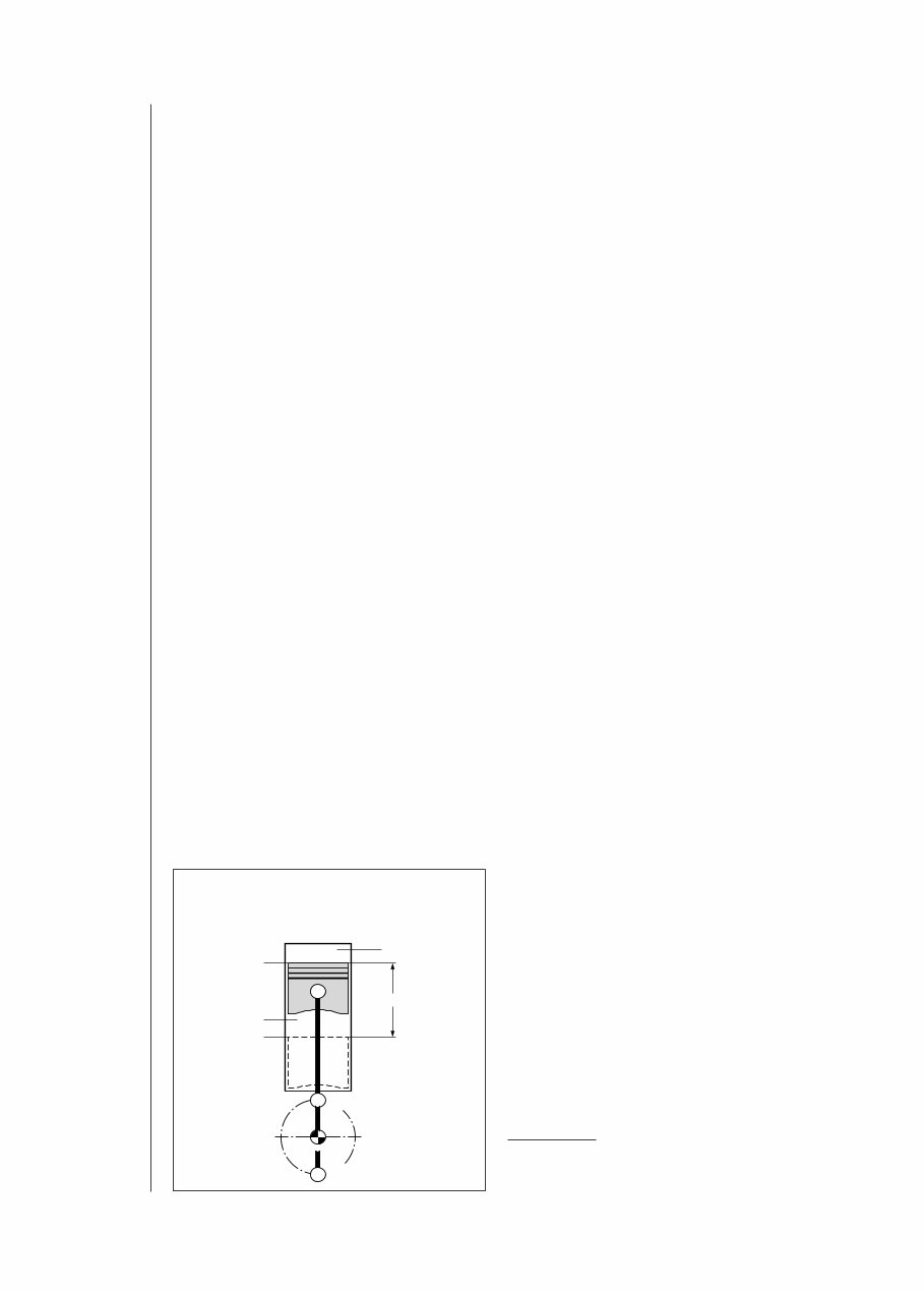
The spark-ignition or Otto-cycle engine Operating concept The spark-ignition or Otto-cycle 1 ) powerplant is an internal-combustion (IC) engine that relies on an externally- generated ignition spark to transform the chemical energy contained in fuel into kinetic energy. Today’s standard spark-ignition engines employ manifold injection for mixture formation outside the combustion chamber. The mixture formation system produces an air/fuel mixture (based on gasoline or a gaseous fuel), which is then drawn into the engine by the suction generated as the pistons descend. The future will see increasing application of systems that inject the fuel directly into the combustion chamber as an alternate concept. As the piston rises, it compresses the mixture in preparation for the timed ignition process, in which externally- generated energy initiates combustion via the spark plug. The heat released in the combustion process pressurizes the cylinder, propelling the piston back down, exerting force against the crankshaft and performing work. After each combustion stroke the spent gases are expelled from the cylinder in preparation for ingestion of a fresh charge of air/fuel mixture. The primary design concept used to govern this gas transfer in powerplants for automotive applications is the four-stroke principle, with two crankshaft revolutions being required for each complete cycle. The four-stroke principle The four-stroke engine employs flow- control valves to govern gas transfer (charge control). These valves open and close the intake and exhaust tracts leading to and from the cylinder: 1st stroke: Induction, 2nd stroke: Compression and ignition, 3rd stroke: Combustion and work, 4th stroke: Exhaust. Induction stroke Intake valve: open, Exhaust valve: closed, Piston travel: downward, Combustion: none. The piston’s downward motion increases the cylinder’s effective volume to draw fresh air/fuel mixture through the passage exposed by the open intake valve. Compression stroke Intake valve: closed, Exhaust valve: closed, Piston travel: upward, Combustion: initial ignition phase. Combustion in the gasoline engine 2 Combustion in the gasoline engine Reciprocating piston-engine design concept OT = TDC (Top Dead Center); UT = BDC (Bottom Dead Center), V h Swept volume, V C Compressed volume, s Piston stroke. Fig. 1 UMM0001E OT UT OT UT V h s V C 1 ) After Nikolaus August Otto (1832 –1891), who unveiled the first four-stroke gas-compression engine at the Paris World Exhibition in 1876.
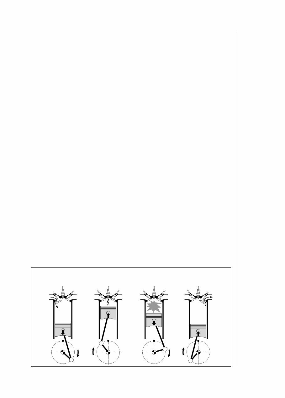
As the piston travels upward it reduces the cylinder’s effective volume to compress the air/fuel mixture. Just before the piston reaches top dead center (TDC) the spark plug ignites the concentrated air/fuel mixture to initiate combustion. Stroke volume V h and compression volume V C provide the basis for calculating the compression ratio ε = (V h +V C )/V C . Compression ratios ε range from 7...13, depending upon specific engine design. Raising an IC engine’s compression ratio increases its thermal efficiency, allowing more efficient use of the fuel. As an example, increasing the compression ratio from 6:1 to 8:1 enhances thermal efficiency by a factor of 12 %. The latitude for increasing compression ratio is restricted by knock. This term refers to uncontrolled mixture inflammation charac- terized by radical pressure peaks. Combustion knock leads to engine damage. Suitable fuels and favorable combustion-chamber configurations can be applied to shift the knock threshold into higher compression ranges. Power stroke Intake valve: closed, Exhaust valve: closed, Piston travel: upward, Combustion: combustion/post-combus- tion phase. The ignition spark at the spark plug ignites the compressed air/fuel mixture, thus initiating combustion and the attendant temperature rise. This raises pressure levels within the cylinder to propel the piston downward. The piston, in turn, exerts force against the crankshaft to perform work; this process is the source of the engine’s power. Power rises as a function of engine speed and torque (P = M⋅ϖ). A transmission incorporating various conversion ratios is required to adapt the combustion engine’s power and torque curves to the demands of automotive operation under real-world conditions. Exhaust stroke Intake valve: closed, Exhaust valve: open, Piston travel: upward, Combustion: none. As the piston travels upward it forces the spent gases (exhaust) out through the passage exposed by the open exhaust valve. The entire cycle then recommences with a new intake stroke. The intake and exhaust valves are open simultaneously during part of the cycle. This overlap exploits gas-flow and resonance patterns to promote cylinder charging and scavenging. Otto cycle 3 Operating cycle of the 4-stroke spark-ignition engine Fig. 2 UMM0011E Stroke 1: Induction Stroke 2: Compression Stroke 3: Combustion Stroke 4: Exhaust
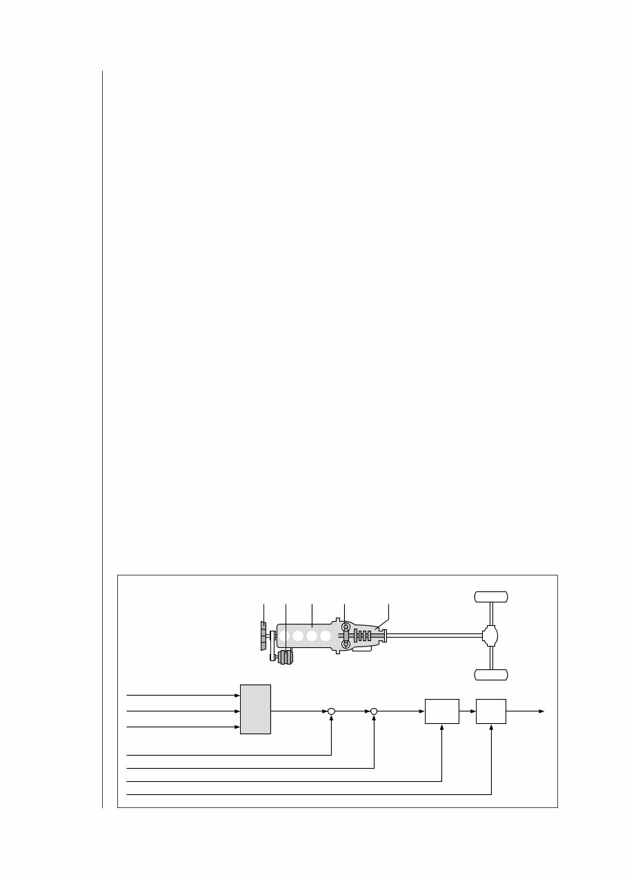
Technical requirements Spark-ignition (SI) engine torque The power P furnished by the spark- ignition engine is determined by the available net flywheel torque and the engine speed. The net flywheel torque consists of the force generated in the combustion process minus frictional losses (internal friction within the engine), the gas- exchange losses and the torque required to drive the engine ancillaries (Figure 1). The combustion force is generated during the power stroke and is defined by the following factors: – The mass of the air available for combustion once the intake valves have closed, – The mass of the simultaneously available fuel, and – The point at which the ignition spark initiates combustion of the air/fuel mixture. Primary engine- management functions The engine-management system’s first and foremost task is to regulate the engine’s torque generation by controlling all of those functions and factors in the various engine-management subsystems that determine how much torque is generated. Cylinder-charge control In Bosch engine-management systems featuring electronic throttle control (ETC), the “cylinder-charge control” subsystem determines the required induction-air mass and adjusts the throttle-valve opening accordingly. The driver exercises direct control over throttle-valve opening on conventional injection systems via the physical link with the accelerator pedal. Mixture formation The “mixture formation” subsystem cal- culates the instantaneous mass fuel requirement as the basis for determining the correct injection duration and optimal injection timing. Gasoline- engine management 4 Gasoline- engine management Driveline torque factors 1 Ancillary equipment (alternator, a/c compressor, etc.), 2 Engine, 3 Clutch, 4 Transmission. UMM0545-1E Fig. 1 Air mass (fresh induction charge) Fuel mass Ignition angle (firing point) Engine Gas-transfer and friction Ancillaries Clutch/converter losses and conversion ratios Transmission losses and conversion ratios Combustion output torque Engine output torque Flywheel torque Drive force – – – – Clutch Trans- mission 1 1 2 3 4
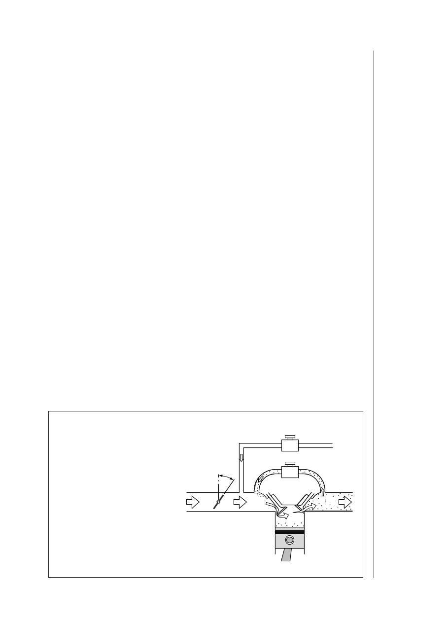
Cylinder charge 5 Ignition Finally, the “ignition” subsystem de- termines the crankshaft angle that corresponds to precisely the ideal instant for the spark to ignite the mixture. The purpose of this closed-loop control system is to provide the torque demanded by the driver while at the same time satisfying strict criteria in the areas of – Exhaust emissions, – Fuel consumption, – Power, – Comfort and convenience, and – Safety. Cylinder charge Elements The gas mixture found in the cylinder once the intake valve closes is referred to as the cylinder charge, and consists of the inducted fresh air-fuel mixture along with residual gases. Fresh gas The fresh mixture drawn into the cylinder is a combination of fresh air and the fuel entrained with it. While most of the fresh air enters through the throttle valve, supplementary fresh gas can also be drawn in through the evaporative- emissions control system (Figure 2). The air entering through the throttle-valve and remaining in the cylinder after intake- valve closure is the decisive factor defining the amount of work transferred through the piston during combustion, and thus the prime determinant for the amount of torque generated by the engine. In consequence, modifications to enhance maximum engine power and torque almost always entail increasing the maximum possible cylinder charge. The theoretical maximum charge is defined by the volumetric capacity. Residual gases The portion of the charge consisting of residual gases is composed of – The exhaust-gas mass that is not discharged while the exhaust valve is open and thus remains in the cylinder, and – The mass of recirculated exhaust gas (on systems with exhaust-gas recircu- lation, Figure 2). The proportion of residual gas is de- termined by the gas-exchange process. Although the residual gas does not participate directly in combustion, it does influence ignition patterns and the actual combustion sequence. The effects of this residual-gas component may be thoroughly desirable under part-throttle operation. Larger throttle-valve openings to com- pensate for reductions in fresh-gas filling Cylinder charge in the spark-ignition engine 1 Air and fuel vapor, 2 Purge valve with variable aperture, 3 Link to evaporative-emissions control system, 4 Exhaust gas, 5 EGR valve with variable aperture, 6 Mass airflow (barometric pressure p U ), 7 Mass airflow (intake-manifold pressure p s ), 8 Fresh air charge (combustion-chamber pressure p B ), 9 Residual gas charge (combustion-chamber pressure p B ), 10 Exhaust gas (back-pressure p A ), 11 Intake valve, 12 Exhaust valve, α Throttle-valve angle. UMM0544-1Y Fig. 2 1 6 7 10 8 2 3 5 4 11 12 9 α
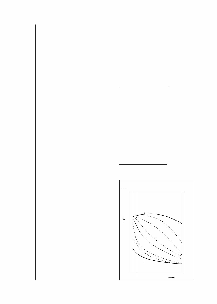
are needed to meet higher torque demand. These higher angles reduce the engine’s pumping losses, leading to lower fuel consumption. Precisely reg- ulated injection of residual gases can also modify the combustion process to reduce emissions of nitrous oxides (NO x ) and unburned hydrocarbons (HC). Control elements Throttle valve The power produced by the spark- ignition engine is directly proportional to the mass airflow entering it. Control of engine output and the corresponding torque at each engine speed is regulated by governing the amount of air being inducted via the throttle valve. Leaving the throttle valve partially closed restricts the amount of air being drawn into the engine and reduces torque generation. The extent of this throttling effect depends on the throttle valve’s position and the size of the resulting aperture. The engine produces maximum power when the throttle valve is fully open (WOT, or wide open throttle). Figure 3 illustrates the conceptual correlation between fresh-air charge density and engine speed as a function of throttle-valve aperture. Gas exchange The intake and exhaust valves open and close at specific points to control the transfer of fresh and residual gases. The ramps on the camshaft lobes determine both the points and the rates at which the valves open and close (valve timing) to define the gas-exchange process, and with it the amount of fresh gas available for combustion. Valve overlap defines the phase in which the intake and exhaust valves are open simultaneously, and is the prime factor in determining the amount of residual gas remaining in the cylinder. This process is known as "internal" exhaust-gas recirculation. The mass of residual gas can also be increased using "external" exhaust-gas recirculation, which relies on a supplementary EGR valve linking the intake and exhaust manifolds. The engine ingests a mixture of fresh air and exhaust gas when this valve is open. Pressure charging Because maximum possible torque is proportional to fresh-air charge density, it is possible to raise power output by compressing the air before it enters the cylinder. Dynamic pressure charging A supercharging (or boost) effect can be obtained by exploiting dynamics within the intake manifold. The actual degree of boost will depend upon the manifold’s configuration as well as the engine’s instantaneous operating point (essentially a function of the engine’s speed, but also affected by load factor). The option of varying intake-manifold geometry while the vehicle is actually being driven, makes it possible to employ dynamic precharging to increase the maximum available charge mass through a wide operational range. Mechanical supercharging Further increases in air mass are available through the agency of Gasoline- engine management 6 Throttle-valve map for spark-ignition engine Throttle valve at intermediate aperture UMM0543-1E Fig. 3 Fresh gas charge RPM min. max. Throttle valve completely open Throttle valve completely closed Idle
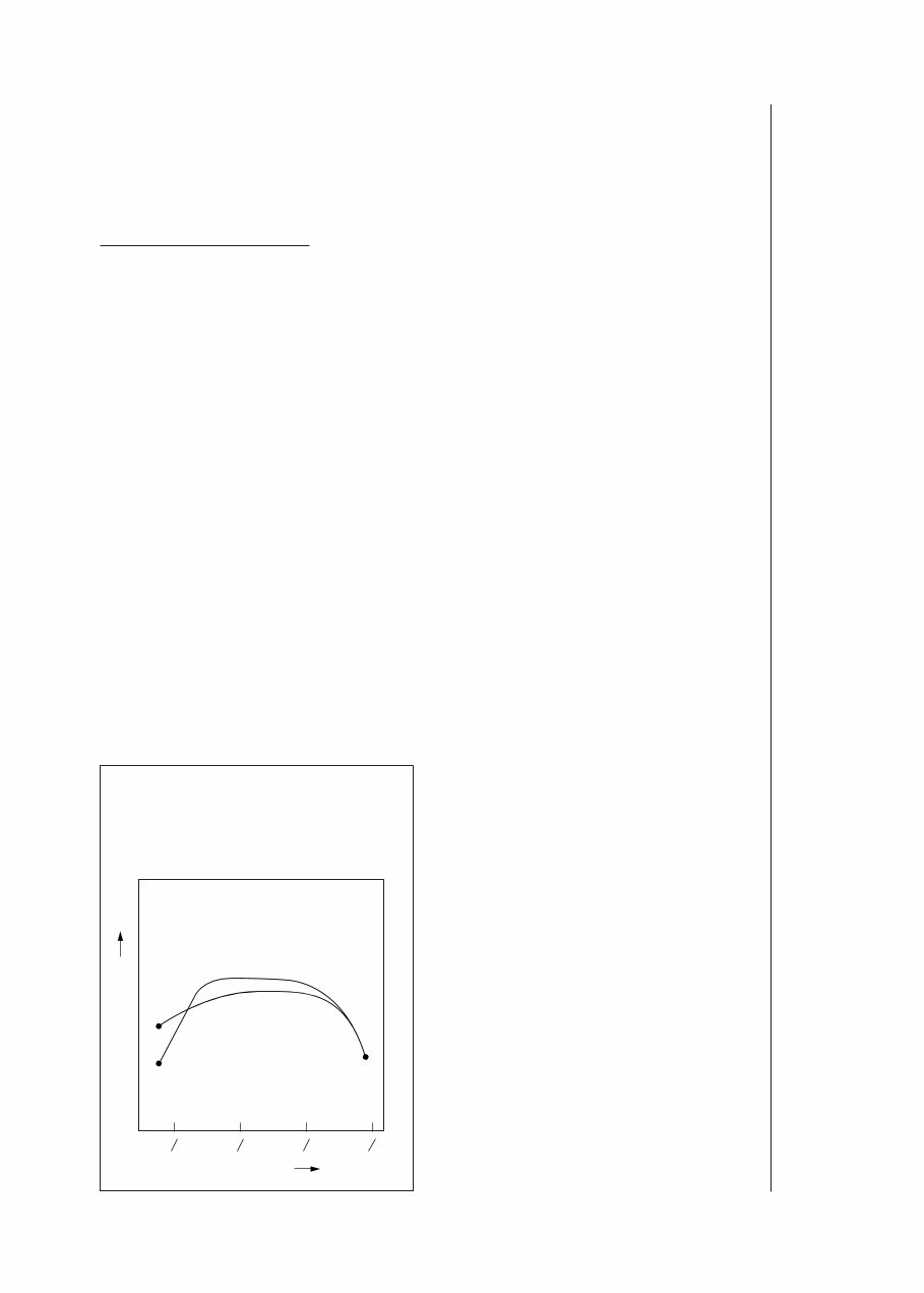
Mixture formation 7 mechanically driven compressors pow- ered by the engine’s crankshaft, with the two elements usually rotating at an in- variable relative ratio. Clutches are often used to control compressor activation. Exhaust-gas turbochargers Here the energy employed to power the compressor is extracted from the exhaust gas. This process uses the energy that naturally-aspirated engines cannot exploit directly owing to the inherent restrictions imposed by the gas ex- pansion characteristics resulting from the crankshaft concept. One disadvantage is the higher back-pressure in the exhaust gas exiting the engine. This back- pressure stems from the force needed to maintain compressor output. The exhaust turbine converts the exhaust-gas energy into mechanical energy, making it possible to employ an impeller to precompress the incoming fresh air. The turbocharger is thus a combination of the turbine in the exhaust- fas flow and the impeller that compresses the intake air. Figure 4 illustrates the differences in the torque curves of a naturally-aspirated engine and a turbocharged engine. Mixture formation Parameters Air-fuel mixture Operation of the spark-ignition engine is contingent upon availability of a mixture with a specific air/fuel (A/F) ratio. The theoretical ideal for complete combustion is a mass ratio of 14.7:1, referred to as the stoichiometric ratio. In concrete terms this translates into a mass relationship of 14.7 kg of air to burn 1 kg of fuel, while the corresponding volumetric ratio is roughly 9,500 litres of air for complete combustion of 1 litre of fuel. The air-fuel mixture is a major factor in determining the spark-ignition engine’s rate of specific fuel consumption. Genuine complete combustion and absolutely minimal fuel consumption would be possible only with excess air, but here limits are imposed by such considerations as mixture flammability and the time available for combustion. The air-fuel mixture is also vital in determining the efficiency of exhaust-gas treatment system. The current state-of- the-art features a 3-way catalytic converter, a device which relies on a stoichiometric A/F ratio to operate at maximum efficiency and reduce un- desirable exhaust-gas components by more than 98 %. Current engines therefore operate with a stoichiometric A/F ratio as soon as the engine’s operating status permits Certain engine operating conditions make mixture adjustments to non- stoichiometric ratios essential. With a cold engine for instance, where specific adjustments to the A/F ratio are required. As this implies, the mixture-formation system must be capable of responding to a range of variable requirements. Torque curves for turbocharged and atmospheric-induction engines with equal power outputs 1 Engine with turbocharger, 2 Atmospheric-induction engine. UMM0459-1E Fig. 4 1 2 1 4 1 2 3 4 1 1 Engine torque M d Engine rpm n n
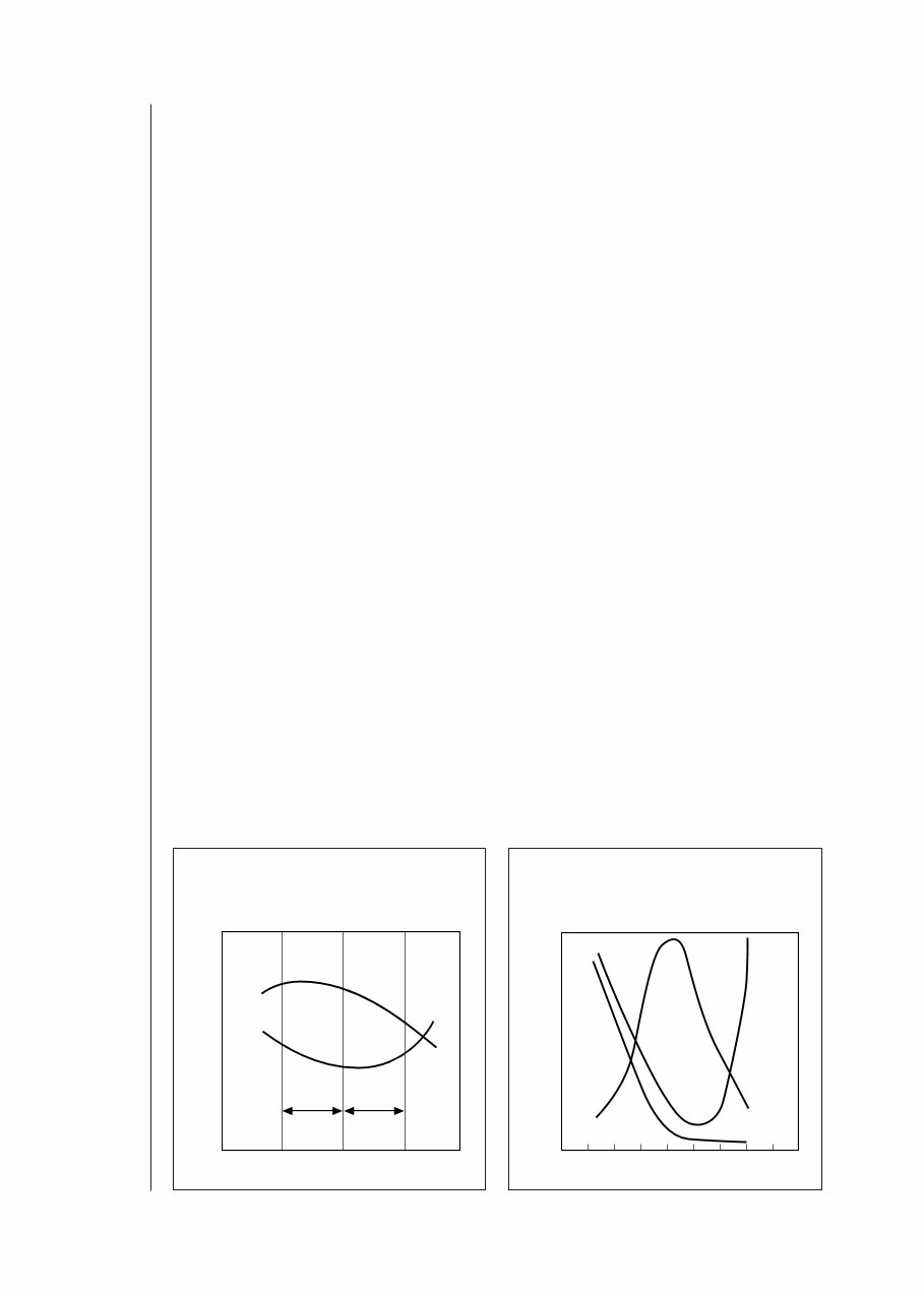
Excess-air factor The designation l (lambda) has been selected to identify the excess-air factor (or air ratio) used to quantify the spread between the actual current mass A/F ratio and the theoretical optimum (14.7:1): λ = Ratio of induction air mass to air requirement for stoichiometric com- bustion. λ = 1: The inducted air mass corresponds to the theoretical requirement. λ < 1: Indicates an air deficiency, producing a corresponding rich mixture. Maximum power is derived from λ = 0.85...0.95. λ > 1: This range is characterized by excess air and lean mixture, leading to lower fuel consumption and reduced power. The potential maximum value for λ – called the “lean-burn limit (LML)” – is essentially defined by the design of the engine and of its mixture for- mation/induction system. Beyond the lean-burn limit the mixture ceases to be ignitable and combustion miss sets in, accompanied by substantial degener- ation of operating smoothness. In engines featuring systems to inject fuel directly into the chamber, these operate with substantially higher excess-air factors (extending to λ = 4) since com- bustion proceeds according to different laws. Spark-ignition engines with manifold injection produce maximum power at air deficiencies of 5...15 % (λ = 0.95...0.85), but maximum fuel economy comes in at 10...20 % excess air (λ = 1.1...1.2). Figures 1 and 2 illustrate the effect of the excess-air factor on power, specific fuel consumption and generation of toxic emissions. As can be seen, there is no single excess-air factor which can simultaneously generate the most favorable levels for all three factors. Air factors of λ = 0.9...1.1 produce “conditionally optimal” fuel economy with “conditionally optimal” power generation in actual practice. Once the engine warms to its normal operating temperature, precise and consistent maintenance of λ = 1 is vital for the 3-way catalytic treatment of exhaust gases. Satisfying this re- quirement entails exact monitoring of induction-air mass and precise metering of fuel mass. Optimal combustion from current en- gines equipped with manifold injection relies on formation of a homogenous mixture as well as precise metering of the injected fuel quantity. This makes effective atomization essential. Failure to satisfy this requirement will foster the formation of large droplets of condensed fuel on the walls of the intake tract and in the combustion chamber. These droplets will fail to combust completely and the ultimate result will be higher HC emissions. Gasoline- engine management 8 Effects of excess-air factor λ on power P and specific fuel consumption b e . a Rich mixture (air deficiency), b Lean mixture (excess air). UMK0033E Fig. 1 Effect of excess-air factor λ on untreated exhaust emissions UMK0032E Fig. 2 0.8 1.0 1.2 a b P b e Power P , Specific fuel consumption b e Excess-air factor λ 0.6 1.0 1.4 Relative quantities of CO; HC; NO X Excess-air factor λ 0.8 1.2 CO HC NO X
This manual, the BOSCH HANDBOOK K D L LH JETRONIC FUEL INJECTION EMISSIONS TECHNICAL INSTRUCTION, is a comprehensive resource for individuals interested in the technical aspects of this brand. It is readily accessible without any barriers to access.
Containing direct technical details from the manufacturer, this manual provides complete information on the brand, catering to both maintenance and repairs. It is a valuable resource for professional mechanics and DIY enthusiasts alike.
Developed with the aim of offering quality information, this car service manual includes various equipment and diagrams to assist in diagnostics, repair, and maintenance of cars.
Upon accessing this manual, users can easily print each section and gain access to step-by-step instructions, pictures, diagrams, assembly, disassembly, cleaning, and maintenance details for the BOSCH HANDBOOK K D L LH JETRONIC FUEL INJECTION EMISSIONS TECHNICAL INSTRUCTION.
The manual covers a wide range of maintenance and repair details, including mechanical and technical specifications of the vehicle, introductory mechanics, equipment elevation, collisions, products and supplies, painting, and descriptions of various vehicle parts.
Embracing the digital age, this manual provides an environmentally friendly and instant alternative to printed books, allowing users to access the information they need with just one click.
Don't wait weeks or months for a printed manual and pay postage when you can access everything you need instantly and start your car repair tasks immediately.
Recently Viewed
5,521,897Happy Clients
2,594,462eManuals
1,120,453Trusted Sellers
15Years in Business
Price:
Actual Price:
bosch handbook k D L LH jetronic fuel injection emissions te