

MITSUBISHI M.U.T 3 III MUT3 MUTIII MUT OWNER USER OPERManual
What's Included?
Fast Download Speeds
Online & Offline Access
Access PDF Contents & Bookmarks
Full Search Facility
Print one or all pages of your manual
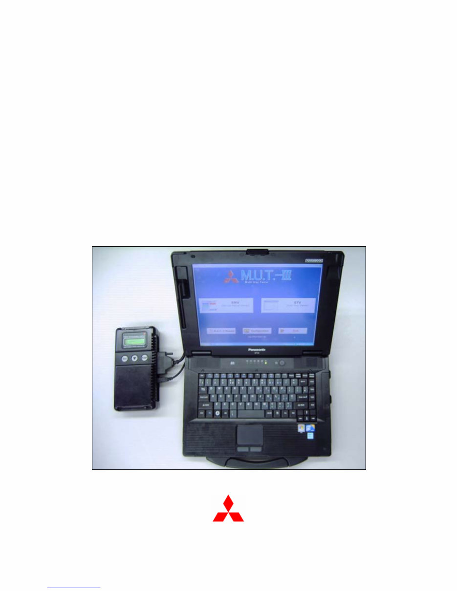
M.U.T.- III Owner’s Manual
Multi Use Tester
< Ver. 20.0 >
MITSUBISHI MOTORS
Downloaded from www.Manualslib.com manuals search engine

Foreword
This manual explains M.U.T.-III: functions, operating procedures, and other related information.
By reading this manual you will obtain a basic understanding of M.U.T.-III and Vehicle
Communication Interface (hereafter abbreviated as V.C.I.) functions and methods of operation.
Because there are differences in M.U.T.-III methods of operation due to the vehicle electronic
control system, be sure to read this manual and Online Help prior to operation.
This manual was written based on the Dec. 2010 version of the M.U.T.-III system.
Please note that the information herein may not always agree with your version of the M.U.T.-III
system due to system specification changes and version upgrades.
Please take good care of this manual along with your M.U.T.-III product.
M.U.T.-III Owner's Manual
Downloaded from www.Manualslib.com manuals search engine

Table of Contents
Chapter 1 Product Overview ........................................................................................ 1
1-1. Precautions............................................................................................................................... 1
1-2. V.C.I. Outline Drawing and Component Names ........................................................................ 2
1-3. M.U.T.-III Components Explanations ........................................................................................ 3
1-4. Harness Connection Method .................................................................................................... 5
1-5. Combination Chart of Harness and Vehicle .............................................................................. 6
Chapter 2 M.U.T.-III Functions...................................................................................... 8
2-1. Basic Functions ........................................................................................................................ 8
2-2. V.C.I. Functions ........................................................................................................................ 9
Chapter 3 Operating M.U.T.-III ..................................................................................... 11
3-1. Starting and Shutting the M.U.T.-III System ........................................................................... 11
3-2. Screen Explanations ............................................................................................................... 13
3-3. Basic Flow to Start Diagnosis ................................................................................................. 15
3-4. Option Settings ....................................................................................................................... 19
3-5. Useful Functions ..................................................................................................................... 20
Chapter 4 Diagnosis Function ................................................................................... 21
4-1. Diagnostic Trouble Code ........................................................................................................ 21
4-2. Data List (Service Data monitor) ............................................................................................. 24
4-3. Actuator Test ........................................................................................................................... 27
4-4. V.C.I. Stand-alone Diagnosis .................................................................................................. 30
4-5. All DTCs.................................................................................................................................. 35
Chapter 5 Special Function (Calibration & Setting) ................................................. 38
5-1. ECU Information ..................................................................................................................... 38
5-2. Learned Value Reset .............................................................................................................. 38
5-3. Steering Angle Sensor Calibration .......................................................................................... 39
5-4. Lateral G Sensor Calibration .................................................................................................. 41
Chapter 6 Drive Recorder........................................................................................... 42
6-1. How to Record the Data ......................................................................................................... 42
6-2. Recorded Data Handling ........................................................................................................ 54
6-3. Display and Analysis of the Recorded Data ............................................................................ 59
Chapter 7 SWS Monitor .............................................................................................. 65
7-1. SWS Monitor Operation .......................................................................................................... 65
Chapter 8 CAN Bus Diagnosis................................................................................... 74
8-1. Diagnosing the CAN Bus ........................................................................................................ 74
M.U.T.-III Owner's Manual
Downloaded from www.Manualslib.com manuals search engine

Chapter 9 ECU Reprogramming ................................................................................ 75
9-1. Process Flow Chart ................................................................................................................ 75
9-2. Equipments ............................................................................................................................. 76
9-3. Data preparation on PC from Update CD-ROM...................................................................... 77
9-4. Reprogramming Operation ( V.C.I. alone ).............................................................................. 79
9-5. Reprogramming Operation ( V.C.I. - PC connected ) .............................................................. 86
9-6. Reprogramming by CAN communication................................................................................ 90
9-7. Troubleshooting of Reprogramming........................................................................................ 93
Chapter 10 Computer Diagnosis ............................................................................... 94
10-1. Operation method of MiEV Computer Diagnosis .................................................................. 94
Chapter 11 Measurement Functions ....................................................................... 100
11-1. Injector-Type Fuel Consumption Measurement .................................................................. 100
11-2. Electricity Consumption Measurement ................................................................................ 102
11-3. Fuel pressure, Voltage, Ohmmeter, Oscilloscope ............................................................... 106
Chapter 12 How to Use (Special Case) ................................................................... 109
12-1. Copy Coding ....................................................................................................................... 109
12-2. Chassis No. / VIN Writing and Chassis No. / VIN Information ............................................ 110
12-3. Coding Operation................................................................................................................ 114
12-4. Customization Operation .................................................................................................... 118
Chapter 13 Troubleshooting Procedures................................................................ 121
13-1. Individual Troubleshooting Procedures ............................................................................... 121
13-2. Troubleshooting Procedures on V.C.I. Firmware Update .................................................... 123
13-3. Troubleshooting of V.C.I. Stand-alone Diagnosis ................................................................ 126
13-4. Troubleshooting of Reprogramming.................................................................................... 127
Chapter 14 Reference Material ................................................................................ 131
14-1. V.C.I. Electrical Properties .................................................................................................. 131
Appendix ................................................................................................................... 132
<< Terminology >> ....................................................................................................................... 132
<< Screen Button Explanations >> .............................................................................................. 134
Downloaded from www.Manualslib.com manuals search engine
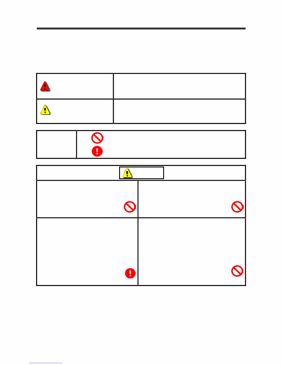
For Your Safety
To ensure proper use of this product and prevent personal injury and property damage, various graphic
displays are used in the user’s manual. The graphic displays and respective meanings are described
below.
Warning
Warning messages alert you to a procedure or practice
which, if not followed correctly, could lead to death or serious
injury.
Caution
Caution messages alert you to a procedure or practice
which, if not followed correctly, could lead to serious injury
and/or property damage.
Icon
Examples
The symbol alerts you to a prohibited action.
The symbol alerts you to an action that must be enforced.
Drivers should not operate the unit while
driving.
• Operating the unit while driving may result in
a traffic accident.
Do not plug in or unplug the power AC adapter
with wet hands.
• Doing so results in the risk of electric shock.
When using the cigarette lighter plug to supply
power to the V.C.I. unit, be sure the power
voltage supplied is DC32V or less.
• Applying a voltage greater than DC32V
results in the risk of fire.
• M.U.T.-III as provided to dealers includes
12V accessory / cigarette lighter plug
adapter to power M.U.T.-III during extended
test drives.
Maximum voltage the V.C.I. can withstand is 40V.
Do not use the V.C.I. on systems greater than the
32-volt system mentioned previously.
• Violating this requirement results in the risk of a
ground fault, damage and/or electric shock.
For Your Safety
Warning
Downloaded from www.Manualslib.com manuals search engine
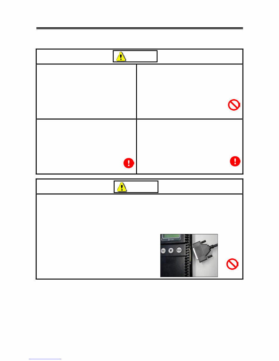
The V.C.I. screen is liquid crystal display or
LCD. In the unlikely event that the display
breaks due to impact, do not let your skin
come in contact with the LCD fluid.
• If your skin comes in contact with the LCD
fluid, wash your skin thoroughly with water.
If skin rash or abnormality occurs seek
medical attention from a doctor.
Do not use the unit if the power AC adapter plug
or cord is damaged or plugging into the outlet is
loose.
• Use under such conditions may result in
electric shock, an electric short and/or fire.
Be sure to hold the harness connector when
disconnecting from the vehicle. Do not
disconnect the harness by pulling on the cord.
• Pulling the cord rather than the connector
may result in damage to the lead wire inside
the cord, thereby causing a short and
possibly starting a fire.
Unplug the power AC adapter from the outlet
when the unit is not in use.
• Failure to do so may result in injury, burns,
electric shock caused by insulation
deterioration, or fire due to a short circuit.
When the harness is connected to the V.C.I., be sure to check the top and bottom of the
connector and connect the harness perpendicularly to the connector of the V.C.I.
Connecting at an angle may result in bending of the pins of the connector.
Check for the secure connection of the harness before tightening of the screw locks.
• The bent pin may contact the connector case, thereby causing an electric short which
leads to damage to the V.C.I.
Warning
Warning
For Your Safety
Downloaded from www.Manualslib.com manuals search engine

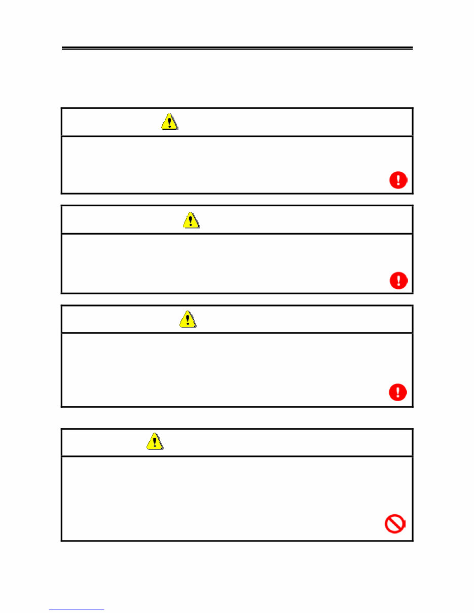
Please Note
Do not expose the PC or V.C.I. to direct sunlight or high temperatures, or leave the unit in
sun-heated cars. Such action may result in system failure.
Store the PC and V.C.I. in a dry environment at room temperatures.
Moving the PC and V.C.I. to a location with a very different temperature and humidity than that of
the previous location may result in external or internal condensation. Caution is required.
Protect the PC and V.C.I. from exposure to elements such as rain, dirt, dust, food and liquids.
Be careful when handling the PC and V.C.I. Dropping the units may result in damage.
Do not expose either unit to engine oil, gasoline, antifreeze or battery acid. Also, do not clean the
PC or V.C.I. case using solutions such as thinner or benzene. Doing so may result in deterioration
of the case surface.
Prior to connecting the M.U.T.-III main harness between the V.C.I. and vehicle, turn the IG switch
to OFF.
• Connecting the V.C.I. harness with the IG switch ON may damage the V.C.I. programming.
Use only the power AC adapter included with the PC (or approved replacement), power cigarette
plug, other probes, main harness and other cables.
• Use of unspecified parts may result in damage or malfunction due to excess voltage or
insufficient contact.
The LCD display of this unit turns off when the supplied voltage is less the DC 8V. This is not an
error.
The power supplied should be from 8VDC to 32VDC.
Keep all V.C.I. connectors and openings away from dirt and static electricity. Exposure to dirt and
static electricity may result in malfunction and damage.
For Your Safety
Downloaded from www.Manualslib.com manuals search engine
1
Chapter 1 Product Overview
1-1. Precautions
Service Work Precautions
• Be sure to follow all basic service work precautions when using M.U.T.-III during vehicle
inspection and service work.
• For detailed information regarding service work precautions, refer to the service instruction
manual of each vehicle.
Work Precautions
• When performing vehicle inspection work at the work site with the engine running, either use an
exhaust gas discharger or ventilate the area sufficiently.
• When working on a vehicle, be sure to apply the parking brake and set wheel chocks in place to
prevent the car from moving.
Driving Precautions
• If you wish to use M.U.T.-III while driving the target vehicle, first verify that all parts are properly
assembled.
• While driving, always have an assistant operate M.U.T.-III.
• Be sure that the M.U.T.-III main harness and other cables will not interfere with driving.
• Install and remove the PC and V.C.I. with the vehicle parked, IG switch OFF.
PC Usage Limitations
Do Not Install Software on the PC
• The M.U.T.-III PC is a special service tool. Do not install any software other than M.U.T.-III
software onto the unit. Installation of other software results in the risk of M.U.T.-III system
failure.
• Any unauthorized software will not be supported. Technical support for units with
unauthorized software will be charged additional technical support fees to return the unit to its
authorized state of operation.
• All unauthorized software will be erased with each new upgrade.
Precautions
Downloaded from www.Manualslib.com manuals search engine
2
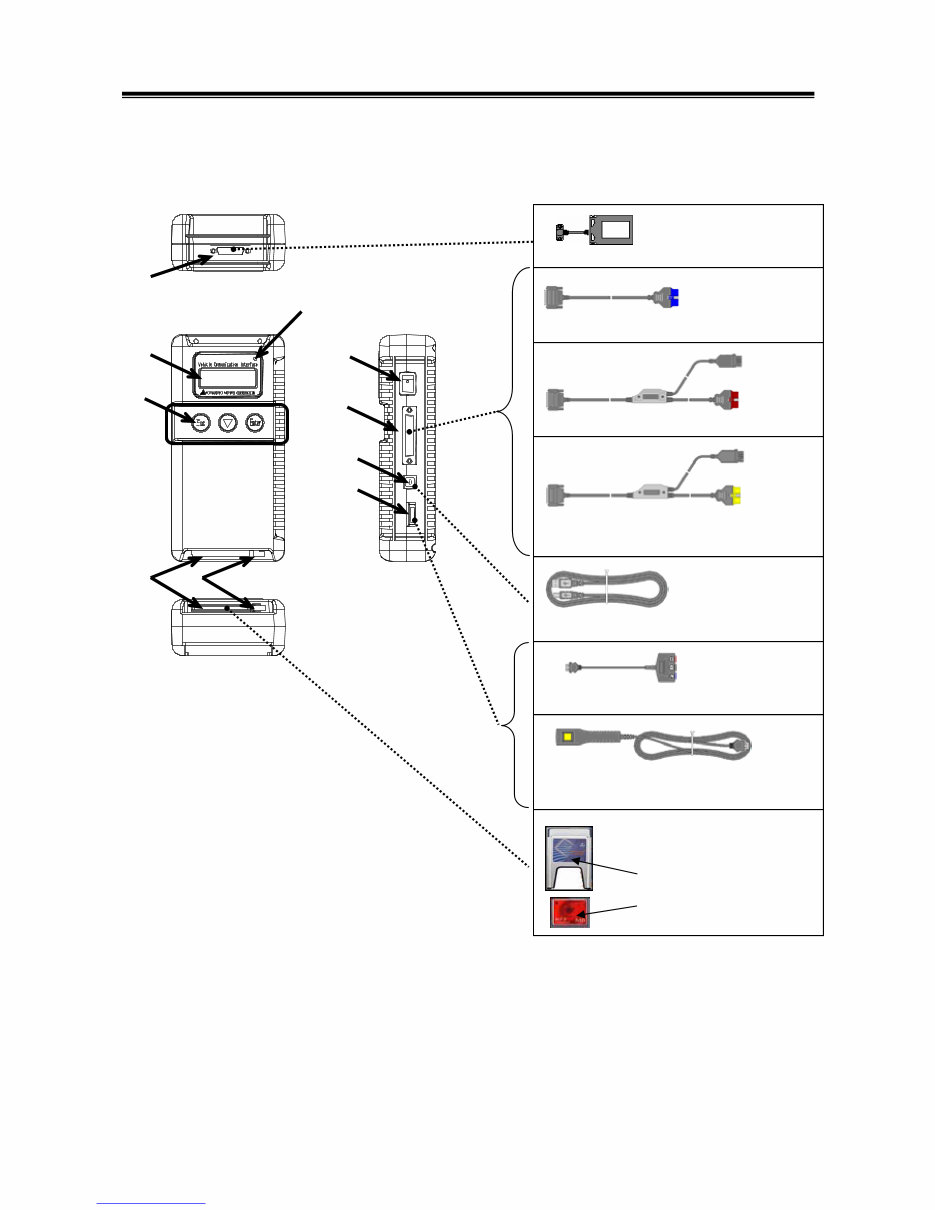
1-2. V.C.I. Outline Drawing and Component Names
The names of the V.C.I. components are indicated in the figure below.
<<Component Names>>
1. I/F cartridge terminal
2. LCD screen
3. Indicator lamp
4. Operation button
(Used with V.C.I. functions)
5. Memory card removal lever
6. Memory card insertion port
7. Power switch
8. Main harness terminal
9. USB terminal
10. Trigger terminal
V.C.I. Outline Drawing and Component Names
Trigger harness (MB991826)
(Not available in US)
CF memory card
& adapter
(MB991853, MB992228)
(MB991939)
I/F cartridges
M.U.T.-III main harness A (MB991910)
M.U.T.-III main harness B (MB991911)
USB cable (MB991827)
Measurement adapter (MB991825)
6
1
8
9
10
3
4
5
2 7
M.U.T.-III main harness C (MB991914)
(For US only)
Downloaded from www.Manualslib.com manuals search engine
3
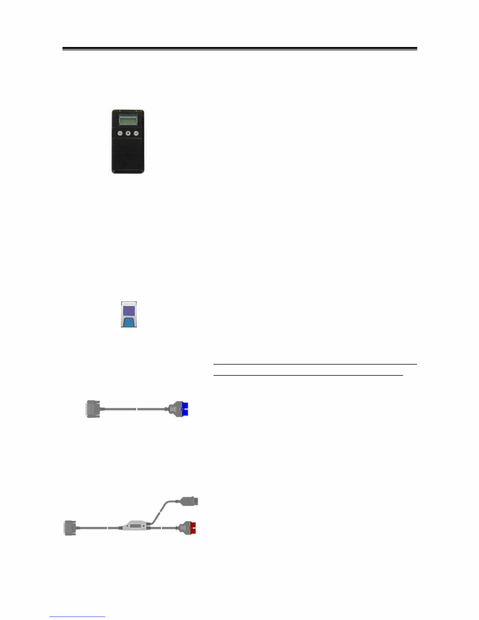
1-3. M.U.T.-III Components Explanations
(1) Vehicle Communication Interface (V.C.I.) (MB991824)
A communication interface used to connect the vehicle
ECUs and the PC.
1. When connected with the PC
• Vehicle diagnosis (Interactive fault diagnosis)
• SWS communication & CAN communication support
• Drive recorder
• ECU reprogramming
• Volt, Ohm, measurement
• Fuel pressure measurement (Not available in US)
2. When used with the V.C.I. unit (disconnected from PC)
• V.C.I. Stand-alone diagnosis
• Drive recorder
• ECU reprogramming
• Volt, Ohm measurement
• Belt Tension measurement
(2) Memory Card
Stores data for ECU reprogramming, drive recorder, etc.
This is a standard, off-the-shelf memory card. The one
provided (with reprogramming data) is a Compact Flash
memory card (MB991853, MB992228) inserted into the CF
card adapter (MB991939).
It is necessary to initialize a Compact Flash memory card
by FAT16 and FAT32 format. (NTFS format cannot use)
(3) M.U.T.-III Main Harness A (MB991910)
Used when connecting the V.C.I. with vehicles that have
only one 16-pin diagnosis connector.
• Supports fault diagnosis and ECU updating on the
above-described vehicles
• Supports the CAN communication system
(4) M.U.T.-III Main Harness B (MB991911)
Used when connecting V.C.I. with vehicles that have a
16-pin + 12-pin or 16-pin + 13-pin diagnosis connector.
For models equipped with only 12-pin (or 12-pin + 12-pin)
diagnosis connector, connect the M.U.T.-II adapter harness
(MB991498) to the end of this harness in the same as
M.U.T.-II, and power is supplied from the cigarette lighter
socket.
M.U.T.-III Components Explanations
Downloaded from www.Manualslib.com manuals search engine
You're Reading a Preview
What's Included?
Fast Download Speeds
Online & Offline Access
Access PDF Contents & Bookmarks
Full Search Facility
Print one or all pages of your manual
$30.99
Viewed 81 Times Today


Secure transaction
What's Included?
Fast Download Speeds
Online & Offline Access
Access PDF Contents & Bookmarks
Full Search Facility
Print one or all pages of your manual
$30.99
The M.U.T. III Owners Manual is a comprehensive guide for utilizing the Multi Use Tester (M.U.T.) Ver 7. This manual provides essential technical information for both professional mechanics and DIY enthusiasts. It contains detailed instructions on how to effectively use the M.U.T. III for diagnosing and troubleshooting vehicle electronic systems. Whether you are a seasoned mechanic or an automotive enthusiast, this manual equips you with the knowledge needed to efficiently perform vehicle repairs and maintenance tasks.


