WABCO HYDRAULIC POWER BRAKE (HPB) SYSTEM MAINTENANCE MANUAL
Service Notes Information contained in this publication was in effect at the time the publication was approved for printing and is subject to change without notice or liability. WABCO reserves the right to revise the information presented or to discontinue the production of parts described at any time. WABCO Maintenance Manual MM-0401 (Revised 08-18) About This Manual This manual contains maintenance procedures for WABCO’s Hydraulic Power Brake (HPB) system for trucks, tractors and buses. Before You Begin 1. Read and understand all instructions and procedures before you begin to service components. 2. Read and observe all Warning and Caution hazard alert messages in this publication. They provide information that can help prevent serious personal injury, damage to components, or both. 3. Follow your company’s maintenance and service, installation, and diagnostics guidelines. 4. Use special tools when required to help avoid serious personal injury and damage to components. Hazard Alert Messages and Torque Symbols WARNING A Warning alerts you to an instruction or procedure that you must follow exactly to avoid serious personal injury and damage to components. CAUTION A Caution alerts you to an instruction or procedure that you must follow exactly to avoid damage to components. @ This symbol alerts you to tighten fasteners to a specified torque value. How to Obtain Additional Maintenance, Service and Product Information Publications Refer to the following publications for more information on servicing WABCO’s Hydraulic Power Brake (HPB) systems. Maintenance Manual 38, Hydraulic ABS for Medium-Duty Trucks, Buses and Motor Home Chassis (C Version Hydraulic ABS) Maintenance Manual 39, Hydraulic ABS for Medium-Duty Trucks, Buses and Motor Home Chassis (D Version Hydraulic ABS) Maintenance Manual MM-0677, Hydraulic Anti-Lock Braking Systems (HABS) for Medium-Duty Trucks, Buses and Motor Home Chassis (E Version Hydraulic ABS) Contact WABCO North America Customer Care at 855-228-3203 (United States and Canada); 001-800-889-1834 (Mexico); or email wnacustomercare@wabco-auto.com. If Tools and Supplies are Specified in This Manual Call Meritor’s Commercial Vehicle Aftermarket at 888-725-9355 to obtain tools and supplies.
Contents pg. pg. i Asbestos and Non-Asbestos Fibers 1 Section 1: Introduction Overview System Components 3 How the HPB System Works 5 Section 2: Wiring Diagram HPB Wiring Diagram for Multiplex Vehicles 6 HPB Connector Diagram for Multiplex Vehicles 7 HPB Wiring Diagram for Non-Multiplexed Vehicles 8 HPB Connector Diagram for Non-Multiplexed Vehicles 9 Section 3: Troubleshooting and Testing Testing the System WABCO TOOLBOX™ Software Connecting TOOLBOX™ Software 10 Hydraulic Power Brake Menus and Toolbars 14 Standard Testing Test Equipment: Volt-Ohm Meter (VOM) System Requirements and Component Tests Tire Size Range Checking Power, Ground and Load Test 15 Standard Component Testing Indicator Lamps Sensor Adjustment Vehicle Test Drive 16 Safety Features Towing Procedure for Navistar CE Buses 17 Warning Lamps 18 SPN, SID, FMI Diagnostic Trouble Code List 52 Section 4: Removal and Installation Removal Hydraulic Compact Unit 55 Installation Hydraulic Compact Unit 56 Removal HCU Reservoir 57 Installation HCU Reservoir 58 Removal HCU Accumulators 60 Installation HCU Accumulators 62 Removal Electronic Control Unit (ECU) 64 Installation Electronic Control Unit (ECU) 65 Parameter Downloading 68 Removal Hydraulic Compact Unit (HCU) Relay Valve 69 Installation Hydraulic Compact Unit (HCU) Relay Valve 70 Removal Hydraulic Compact Unit (HCU) Pump 71 Installation Hydraulic Compact Unit (HCU) Pump 72 Removal Master Cylinder Replacement Information Master Cylinder 75 Installation Master Cylinder 77 Removal Master Cylinder Reservoir 79 Installation Master Cylinder Reservoir 81 Removal Master Cylinder Foot Brake Switch 82 Installation Master Cylinder Foot Brake Switch Removal Master Cylinder Fluid Level Sensor Switch Installation Master Cylinder Fluid Level Sensor 83 Removal Parking Brake Pressure Supply Valve 85 Installation Parking Brake Pressure Supply Valve 87 Removal Low Pressure Hose 88 Installation Low Pressure Hose 89 Lubrication Wheel Speed Sensor Specification 90 Removal Front Axle Wheel Speed Sensor Installation Front Axle Wheel Speed Sensor 91 Removal Rear Axle Wheel Speed Sensor Installation Rear Axle Wheel Speed Sensor 92 Section 5: Brake Bleeding Procedures 93 Brake Bleeding Procedures Pressure Bleed Procedures Master Cylinder Circuit
Contents pg. pg. 94 Brake Caliper Circuit 97 Spring-Applied/Hydraulic Release Parking Brake Circuit 98 Changing Hydraulic Brake Fluid 99 Brake Fluid Replacement Requirement Filling the Hydraulic Power Brake (HPB) Master Cylinder Reservoir 101 Section 6: Appendix Leak Check Procedure for WABCO HPB System Check the HPB System for Brake Fluid Leaks System Test
Asbestos and Non-Asbestos Fibers i WABCO Maintenance Manual MM-0401 (Revised 08-18) ASBESTOS FIBERS WARNING The following procedures for servicing brakes are recommended to reduce exposure to asbestos fiber dust, a cancer and lung disease hazard. Material Safety Data Sheets are available from WABCO. Hazard Summary Because some brake linings contain asbestos, workers who service brakes must understand the potential hazards of asbestos and precautions for reducing risks. Exposure to airborne asbestos dust can cause serious and possibly fatal diseases, including asbestosis (a chronic lung disease) and cancer, principally lung cancer and mesothelioma (a cancer of the lining of the chest or abdominal cavities). Some studies show that the risk of lung cancer among persons who smoke and who are exposed to asbestos is much greater than the risk for non-smokers. Symptoms of these diseases may not become apparent for 15, 20 or more years after the first exposure to asbestos. Accordingly, workers must use caution to avoid creating and breathing dust when servicing brakes. Specific recommended work practices for reducing exposure to asbestos dust follow. Consult your employer for more details. Recommended Work Practices 1. Separate Work Areas. Whenever feasible, service brakes in a separate area away from other operations to reduce risks to unprotected persons. OSHA has set a maximum allowable level of exposure for asbestos of 0.1 f/cc as an 8-hour time-weighted average and 1.0 f/cc averaged over a 30-minute period. Scientists disagree, however, to what extent adherence to the maximum allowable exposure levels will eliminate the risk of disease that can result from inhaling asbestos dust. OSHA requires that the following sign be posted at the entrance to areas where exposures exceed either of the maximum allowable levels: DANGER: ASBESTOS CANCER AND LUNG DISEASE HAZARD AUTHORIZED PERSONNEL ONLY RESPIRATORS AND PROTECTIVE CLOTHING ARE REQUIRED IN THIS AREA. 2. Respiratory Protection. Wear a respirator equipped with a high-efficiency (HEPA) filter approved by NIOSH or MSHA for use with asbestos at all times when servicing brakes, beginning with the removal of the wheels. 3. Procedures for Servicing Brakes. a. Enclose the brake assembly within a negative pressure enclosure. The enclosure should be equipped with a HEPA vacuum and worker arm sleeves. With the enclosure in place, use the HEPA vacuum to loosen and vacuum residue from the brake parts. b. As an alternative procedure, use a catch basin with water and a biodegradable, non-phosphate, water-based detergent to wash the brake drum or rotor and other brake parts. The solution should be applied with low pressure to prevent dust from becoming airborne. Allow the solution to flow between the brake drum and the brake support or the brake rotor and caliper. The wheel hub and brake assembly components should be thoroughly wetted to suppress dust before the brake shoes or brake pads are removed. Wipe the brake parts clean with a cloth. c. If an enclosed vacuum system or brake washing equipment is not available, employers may adopt their own written procedures for servicing brakes, provided that the exposure levels associated with the employer’ s procedures do not exceed the levels associated with the enclosed vacuum system or brake washing equipment. Consult OSHA regulations for more details. d. Wear a respirator equipped with a HEPA filter approved by NIOSH or MSHA for use with asbestos when grinding or machining brake linings. In addition, do such work in an area with a local exhaust ventilation system equipped with a HEPA filter. e. NEVER use compressed air by itself, dry brushing, or a vacuum not equipped with a HEPA filter when cleaning brake parts or assemblies. NEVER use carcinogenic solvents, flammable solvents, or solvents that can damage brake components as wetting agents. 4. Cleaning Work Areas. Clean work areas with a vacuum equipped with a HEPA filter or by wet wiping. NEVER use compressed air or dry sweeping to clean work areas. When you empty vacuum cleaners and handle used rags, wear a respirator equipped with a HEPA filter approved by NIOSH or MSHA for use with asbestos. When you replace a HEPA filter, wet the filter with a fine mist of water and dispose of the used filter with care. 5. Worker Clean-Up. After servicing brakes, wash your hands before you eat, drink or smoke. Shower after work. Do not wear work clothes home. Use a vacuum equipped with a HEPA filter to vacuum work clothes after they are worn. Launder them separately. Do not shake or use compressed air to remove dust from work clothes. 6. Waste Disposal. Dispose of discarded linings, used rags, cloths and HEPA filters with care, such as in sealed plastic bags. Consult applicable EPA, state and local regulations on waste disposal. Regulatory Guidance References to OSHA, NIOSH, MSHA, and EPA, which are regulatory agencies in the United States, are made to provide further guidance to employers and workers employed within the United States. Employers and workers employed outside of the United States should consult the regulations that apply to them for further guidance. NON-ASBESTOS FIBERS WARNING The following procedures for servicing brakes are recommended to reduce exposure to non-asbestos fiber dust, a cancer and lung disease hazard. Material Safety Data Sheets are available from WABCO. Hazard Summary Most recently manufactured brake linings do not contain asbestos fibers. These brake linings may contain one or more of a variety of ingredients, including glass fibers, mineral wool, aramid fibers, ceramic fibers and silica that can present health risks if inhaled. Scientists disagree on the extent of the risks from exposure to these substances. Nonetheless, exposure to silica dust can cause silicosis, a non-cancerous lung disease. Silicosis gradually reduces lung capacity and efficiency and can result in serious breathing difficulty. Some scientists believe other types of non-asbestos fibers, when inhaled, can cause similar diseases of the lung. In addition, silica dust and ceramic fiber dust are known to the State of California to cause lung cancer. U.S. and international agencies have also determined that dust from mineral wool, ceramic fibers and silica are potential causes of cancer. Accordingly, workers must use caution to avoid creating and breathing dust when servicing brakes. Specific recommended work practices for reducing exposure to non-asbestos dust follow. Consult your employer for more details. Recommended Work Practices 1. Separate Work Areas. Whenever feasible, service brakes in a separate area away from other operations to reduce risks to unprotected persons. 2. Respiratory Protection. OSHA has set a maximum allowable level of exposure for silica of 0.1 mg/m3 as an 8-hour time-weighted average. Some manufacturers of non-asbestos brake linings recommend that exposures to other ingredients found in non-asbestos brake linings be kept below 1.0 f/cc as an 8-hour time-weighted average. Scientists disagree, however, to what extent adherence to these maximum allowable exposure levels will eliminate the risk of disease that can result from inhaling non-asbestos dust. Therefore, wear respiratory protection at all times during brake servicing, beginning with the removal of the wheels. Wear a respirator equipped with a high-efficiency (HEPA) filter approved by NIOSH or MSHA, if the exposure levels may exceed OSHA or manufacturers’ recommended maximum levels. Even when exposures are expected to be within the maximum allowable levels, wearing such a respirator at all times during brake servicing will help minimize exposure. 3. Procedures for Servicing Brakes. a. Enclose the brake assembly within a negative pressure enclosure. The enclosure should be equipped with a HEPA vacuum and worker arm sleeves. With the enclosure in place, use the HEPA vacuum to loosen and vacuum residue from the brake parts. b. As an alternative procedure, use a catch basin with water and a biodegradable, non-phosphate, water-based detergent to wash the brake drum or rotor and other brake parts. The solution should be applied with low pressure to prevent dust from becoming airborne. Allow the solution to flow between the brake drum and the brake support or the brake rotor and caliper. The wheel hub and brake assembly components should be thoroughly wetted to suppress dust before the brake shoes or brake pads are removed. Wipe the brake parts clean with a cloth. c. If an enclosed vacuum system or brake washing equipment is not available, carefully clean the brake parts in the open air. Wet the parts with a solution applied with a pump-spray bottle that creates a fine mist. Use a solution containing water, and, if available, a biodegradable, non-phosphate, water-based detergent. The wheel hub and brake assembly components should be thoroughly wetted to suppress dust before the brake shoes or brake pads are removed. Wipe the brake parts clean with a cloth. d. Wear a respirator equipped with a HEPA filter approved by NIOSH or MSHA when grinding or machining brake linings. In addition, do such work in an area with a local exhaust ventilation system equipped with a HEPA filter. e. NEVER use compressed air by itself, dry brushing, or a vacuum not equipped with a HEPA filter when cleaning brake parts or assemblies. NEVER use carcinogenic solvents, flammable solvents, or solvents that can damage brake components as wetting agents. 4. Cleaning Work Areas. Clean work areas with a vacuum equipped with a HEPA filter or by wet wiping. NEVER use compressed air or dry sweeping to clean work areas. When you empty vacuum cleaners and handle used rags, wear a respirator equipped with a HEPA filter approved by NIOSH or MSHA, to minimize exposure. When you replace a HEPA filter, wet the filter with a fine mist of water and dispose of the used filter with care. 5. Worker Clean-Up. After servicing brakes, wash your hands before you eat, drink or smoke. Shower after work. Do not wear work clothes home. Use a vacuum equipped with a HEPA filter to vacuum work clothes after they are worn. Launder them separately. Do not shake or use compressed air to remove dust from work clothes. 6. Waste Disposal. Dispose of discarded linings, used rags, cloths and HEPA filters with care, such as in sealed plastic bags. Consult applicable EPA, state and local regulations on waste disposal. Regulatory Guidance References to OSHA, NIOSH, MSHA, and EPA, which are regulatory agencies in the United States, are made to provide further guidance to employers and workers employed within the United States. Employers and workers employed outside of the United States should consult the regulations that apply to them for further guidance.
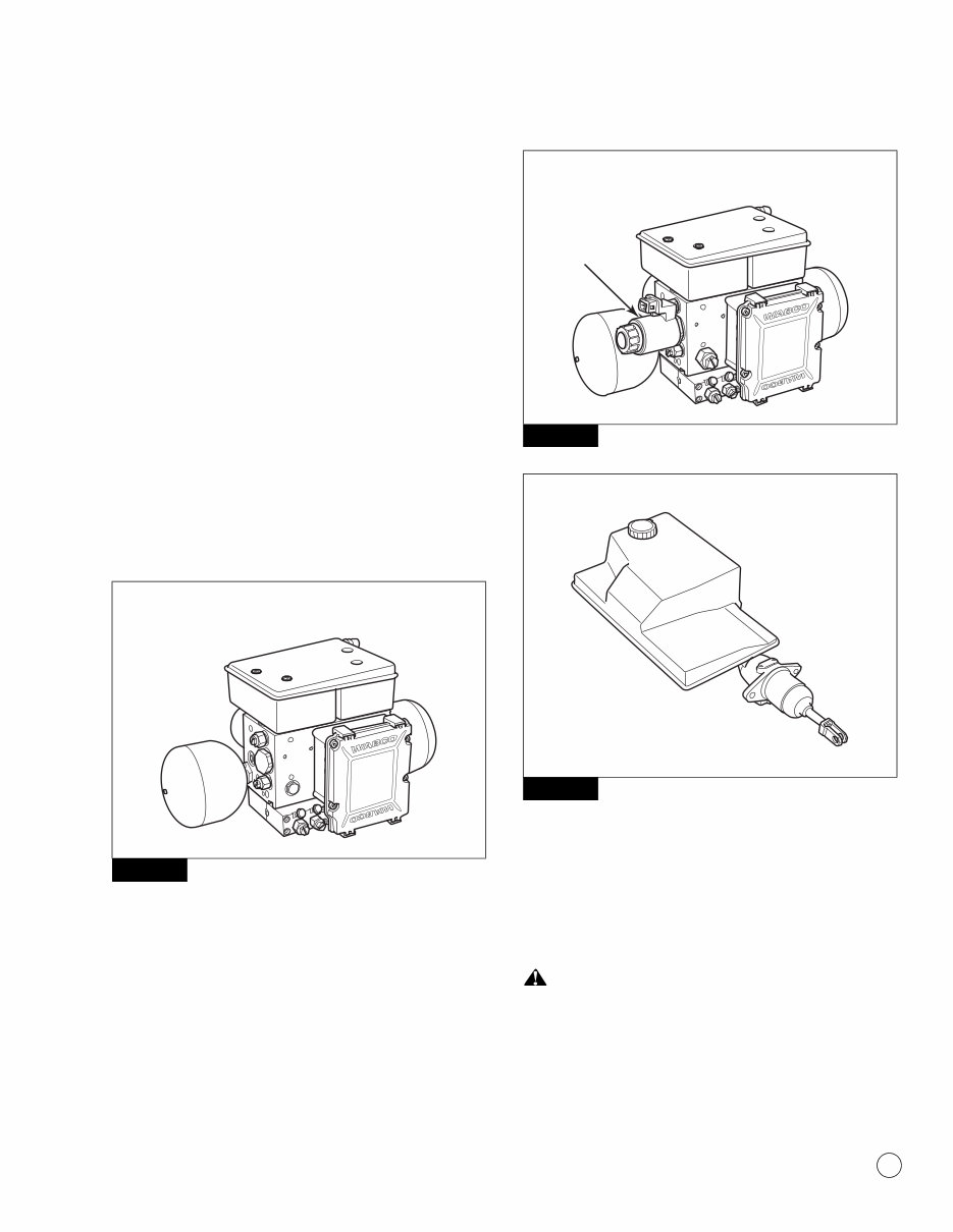
1 Introduction 1 WABCO Maintenance Manual MM-0401 (Revised 08-18) 1 Introduction Overview WABCO’s Hydraulic Power Brake (HPB) is a braking and vehicle control system for Business Class trucks, Classes 4 through 7, and buses that are equipped with hydraulic brakes. The HPB system provides the following functions. Full power brake performance Brake control functions including Anti-Lock Braking System (ABS), Automatic Traction Control (ATC) and Electronic Brake force Distribution (EBD) Optional parking brake control System Components The HPB system consists of two main components — the Hydraulic Compact Unit (HCU) and a dual circuit master cylinder. The HPB system is also available with an optional parking brake pressure supply valve. Figure 1.1 and Figure 1.2 illustrate the HPB system with and without the park brake supply valve. Figure 1.3 illustrates the master cylinder assembly. Figure 1.1 Figure 1.2 Figure 1.3 Hydraulic Compact Unit The HCU consists of an electronic control unit, two independent electric motors driving two piston pumps, two accumulators, a dual circuit fluid reservoir with integrated filters, pressure relief valves, solenoid valves and a dual circuit relay valve. The HCU is mounted to the vehicle frame rail with two brackets. Figure 1.4. WARNING Do not drive the vehicle if a HPB system failure has occurred. Loss of braking ability may occur, resulting in an accident and serious personal injury. The HCU generates the service brake pressure. Figure 1.1 4004474b HCU WITHOUT OPTIONAL POWER PARKING BRAKE SUPPLY VALVE Figure 1.2 Figure 1.3 4004474c HCU WITH OPTIONAL POWER PARKING BRAKE PRESSURE SUPPLY VALVE PRESSURE SUPPLY VALVE 4004475a MASTER CYLINDER ASSEMBLY
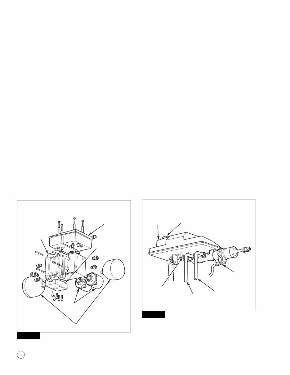
1 Introduction 2 WABCO Maintenance Manual MM-0401 (Revised 08-18) Two pump motors drive the piston pumps to build hydraulic pressure. The pressure is stored in accumulators. The motors are not serviceable. The motors cannot be replaced without replacing the entire HCU. The accumulators are two gas-filled hydraulic accumulators. The accumulators store energy supplied by the pumps. Accumulators are sealed at the factory and are non-refillable. Accumulators may be replaced as a set without replacing the entire HCU. The ECU processes sensor signals and generates solenoid valve commands to reduce, maintain or increase brake pressure for control function. The ECU constantly monitors the pressure in the accumulators, using one pressure sensor per brake circuit. The ECU may be replaced without replacing the complete HCU. The optional pressure supply valve controls the Spring-Applied/ Hydraulic Released (SAHR) parking brake. The pressure supply valve is mounted on the HCU. The pressure supply valve may be replaced without replacing the entire HCU. The dual circuit HCU reservoir holds the hydraulic brake fluid. (The reservoir may be replaced without replacing the entire HCU.) The relay valve is mounted on the bottom of the HCU and may be replaced without replacing the entire HCU. Figure 1.4 Master Cylinder Assembly The dual circuit master cylinder in conjunction with a relay valve provides the translation of brake pedal force into hydraulic braking pressure, and sends the driver’s demand signal to the HCU. Figure 1.5. The foot brake switch provides brake status to the ECU and eliminates the need for a brake light switch. The master cylinder reservoir holds the additional hydraulic brake fluid. The fluid sensor switch monitors fluid level in the master cylinder reservoir. The master cylinder reservoir and both master cylinder switches may be replaced without replacing the entire master cylinder. The master cylinder cap provided by WABCO contains a special gore material that allows the reservoir to breathe, and serves as a filter to help prevent contaminants from getting into the reservoir. This is the only cap approved for use with WABCO HPB. NOTE: The ability of the master cylinder cap to breathe is critical to correct brake system function. If the cap becomes contaminated, it will need to be replaced. Figure 1.5 Figure 1.4 4004476b DUAL CIRCUIT HCU RESERVOIR ECU RELAY VALVE ACCUMULATORS PUMP MOTORS (2) HYDRAULIC COMPACT UNIT WITHOUT PRESSURE SUPPLY VALVE Figure 1.5 4004477a MASTER CYLINDER RESERVOIR FOOT BRAKE SWITCH PRIMARY CIRCUIT (MF-FRONT AXLE) MASTER CYLINDER ASSEMBLY FLUID LEVEL SENSOR SWITCH SECONDARY CIRCUIT (MR-REAR AXLE) VENTED RESERVOIR CAP
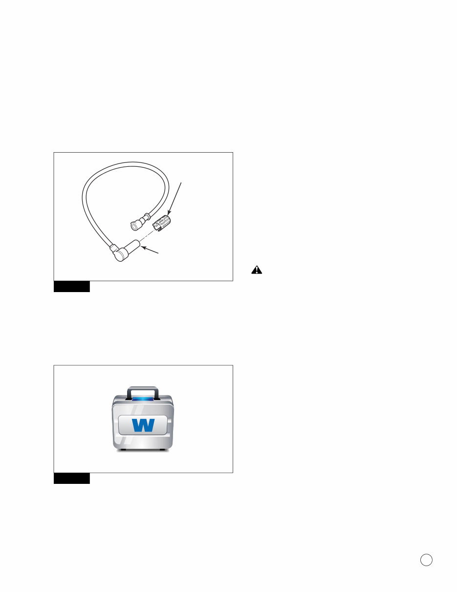
1 Introduction 3 WABCO Maintenance Manual MM-0401 (Revised 08-18) Wheel-End Sensors A WABCO wheel speed sensor is installed at each wheel whose speed is to be monitored. These sensors generate electronic signals which are sent to the ECU. A sensor spring clip holds the wheel speed sensor in place. Figure 1.6. The sensor and sensor clip must be lubricated before installation and whenever wheel-end maintenance is performed. Figure 1.6 TOOLBOX™ Software TOOLBOX™ Software is a PC-based diagnostics program required to diagnose HPB system faults. For HPB, version 9.0 or higher is recommended. TOOLBOX™ Software is available at www.wabco-auto.com. Figure 1.7. Figure 1.7 Low Pressure Hose The Removal and Installation section of this manual contains service information for a low pressure hose which is not produced by WABCO but is an integral part of the HPB system. Spring-Applied Hydraulic Release (SAHR) Parking Brake Canister (Optional) NOTE: The SAHR canister is not produced by WABCO and is an optional feature. Please consult the OEM for maintenance and service information. Refer to Navistar publication TSI-08-04-01. On vehicles equipped with hydraulic parking brakes, the SAHR canister controls the force applied to the parking brake cable. Internal springs are used to apply tension to the parking brake cable, which applies the parking brake. When pressurized brake fluid is routed to the SAHR canister, the hydraulic pressure overcomes the internal springs to relax the parking brake cable, which releases the parking brake. The SAHR parking brake canister is typically located inside the driver’s side frame rail, forward of the rear axles. Vehicles not equipped with hydraulic parking brakes have mechanical or air (Spring Applied Air Released, SAAR) parking brakes. Please consult the OEM for maintenance and service information. WARNING Never drive the vehicle if the parking brake cable is disconnected or if the parking brake system is not operating correctly. Driving the vehicle without a correctly functioning parking brake system can result in an accident and serious personal injury. Parking Brake Switch The parking brake switch (optional) is a three-position electrical switch (apply, neutral and release). It controls the driver-requested operation of the parking brake. How the HPB System Works WABCO’s hydraulic power braking system provides the energy required to actuate the brakes and control the electronic brake force distribution (EBD), ABS and ATC functions. The HCU is activated each time the ignition is turned on or whenever the driver steps on the brake pedal. If the system is equipped with the optional power park brake, the HCU also supplies the energy to release and control the service and park brakes. The WABCO HPB system for trucks is illustrated in Figure 1.8. A complete HPB system layout, with hydraulic brake lines, appears in the Appendix. Figure 1.6 Figure 1.7 4004479a SENSOR SPRING CLIP WHEEL SPEED SENSOR 4011996a
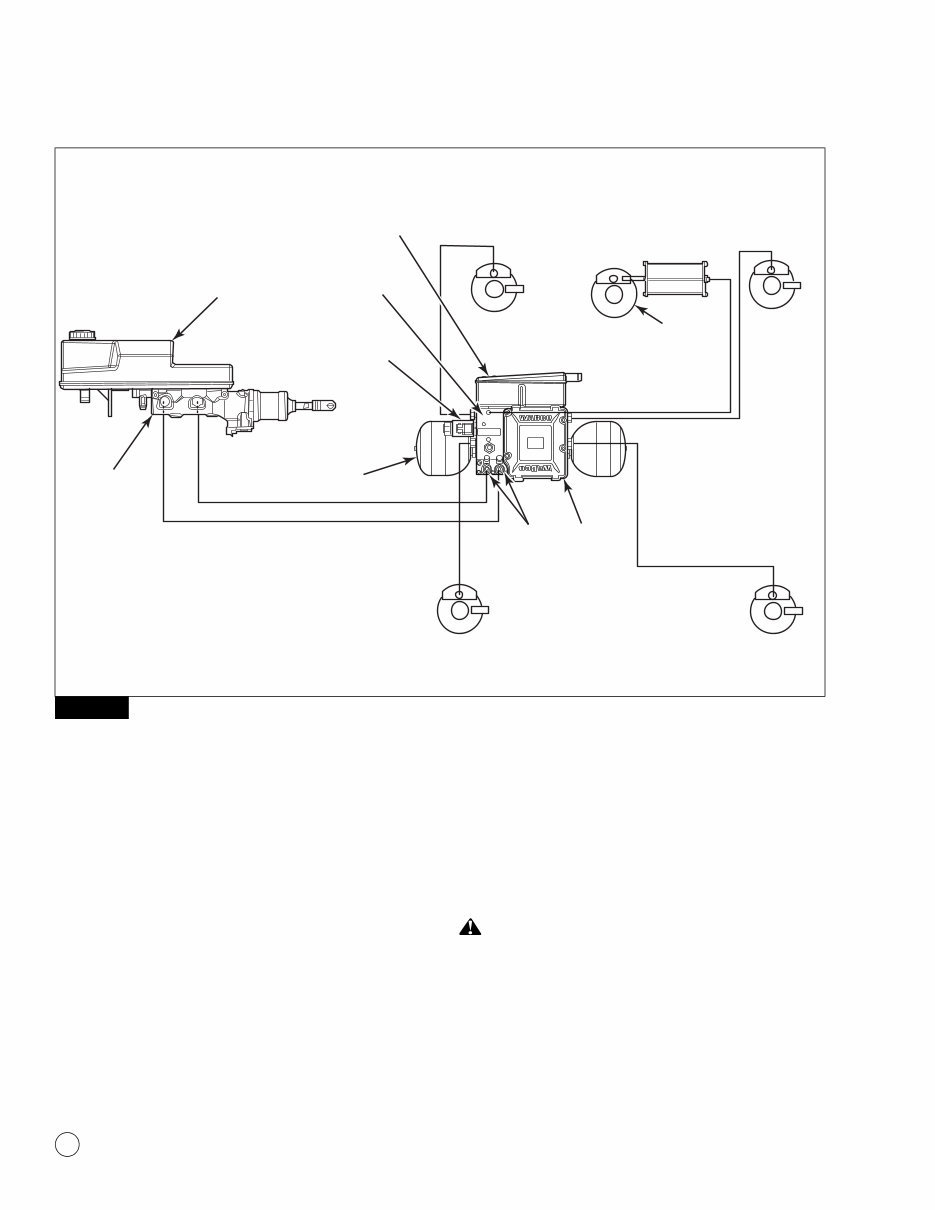
1 Introduction 4 WABCO Maintenance Manual MM-0401 (Revised 08-18) Figure 1.8 Functional Description Hydraulic energy is stored in the gas-filled hydraulic accumulators, one for each circuit. When the vehicle’s ignition is turned on, internal pumps are activated and fill both accumulators with pressurized hydraulic brake fluid. Two internal sensors, one for each accumulator, measure pressure and the ECU continuously monitors and controls pressure. During normal operation, the ECU actuates two separate power drivers for the electric motors, keeping the pressure level within the system at desired limits. Two pressure relief valves provide safety against overpressurization. When the brake pedal is applied, the master cylinder provides a hydraulic signal to the relay valve. Proportional to that signal, the accumulators release pressure to the brake calipers. When the pedal is released, brake fluid returns from the brake calipers to the reservoir, and line pressure is reduced to zero. For ABS, wheel pressure is individually modulated by eight integrated ABS solenoid valves in the ECU/HCU. For ATC, the normally closed ATC solenoid valve in the ECU is actuated and hydraulic energy is supplied to the sensed wheel. At the same time, the normally open ATC valve is actuated to prevent fluid flow back into the reservoir. The brake pressure is then modulated by the corresponding ABS solenoid valves. WARNING Do not install any “add-on” hydraulic devices to the HPB system. A loss of braking ability may occur, resulting in an accident and serious personal injury. Figure 1.8 4004478a FRONT AXLE REAR AXLE HCU RESERVOIR HCU ASSEMBLY PRESSURE SUPPLY VALVE ACCUMULATORS (2) WHEEL-END SENSORS (4) MASTER CYLINDER RESERVOIR MASTER CYLINDER ASSEMBLY PARKING BRAKE ECU HPB SYSTEM LAYOUT RELAY VALVES
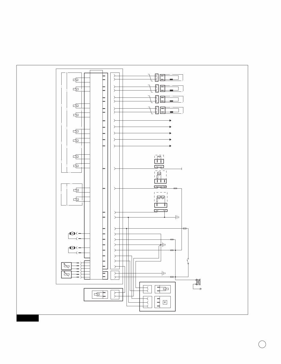
2 Wiring Diagram 5 WABCO Maintenance Manual MM-0401 (Revised 08-18) 2 Wiring Diagram HPB Wiring Diagram for Multiplex Vehicles The WABCO HPB electronic control unit interface wiring diagram for multiplex vehicles is shown in Figure 2.1. Figure 2.1 Figure 2.1 WHEEL PRESSURE MODULATION SOLENOIDS ELECTRONIC CONTROL UNIT ATC–SOLENOIDS 31-PIN CONNECTOR PRESSURE SUPPLY VALVE PARKING BRAKE TRAVEL SWITCH CUTOFF SOLENOID ATC FRONT LEFT IV NC PUMP– MOTOR 2 P P PUMP– MOTOR 1 2-PIN CONNECTOR GRD STUD 1 GRD STUD 3 SENSOR FRONT LEFT SENSOR FRONT RIGHT SENSOR REAR LEFT SENSOR REAR RIGHT GRD STUD 2 +12V BATTERY FEED 30A 30 1 2 A B GROUND IGNITION PIN 7 C + – 30A 30A 5A 5A 3K 1 1 2 2 3 1K 560R 680R 27K IGNITION SWITCH BRAKE SWITCH LOW BRAKE FLUID DIAGNOSE "A" ACC. SAE J1587 DIAGNOSE "B" CAN HIGH ACC. SAE J1939 CAN LOW BRAKE LIGHT SIGNAL 2x0.75 mm2 TWISTED 2x0.75 mm2 TWISTED 2x0.75 mm2 TWISTED 2x0.75 mm2 TWISTED IGNITION REFERENCE GROUND PARKING BRAKE SWITCH * PUMP MOTOR 1 SUPPLY * PUMP MOTOR 1 GROUND * PUMP MOTOR 2 SUPPLY * PUMP MOTOR 2 GROUND * SOLENOID VALVE SUPPLY * SOLENOID VALVE GROUND 2 2 1 1 4 5 7 16 18 17 19 1 6 11 10 9 31 26 14 15 3 24 29 25 30 23 28 22 27 NO OV IV OV IV OV IV OV FRONT RIGHT REAR RIGHT REAR LEFT 4004481a WIRING DIAGRAM FOR MULTIPLEX (MUX) VEHICLES WITH POWER BRAKE OPTION
You're Reading a Preview
What's Included?
Lifetime Access
Fast Download Speeds
Online & Offline Access
Access PDF Contents & Bookmarks
Full Search Facility
Print one or all pages of your manual
$58.99
Wabco Hydraulic Power Brake (HPB) System Service & Repair Manual
The Wabco Hydraulic Power Brake (HPB) System Service & Repair Manual is an indispensable tool for mechanics and technicians specializing in commercial vehicle brake systems. This manual delivers comprehensive information on the service and repair procedures for Wabco's Hydraulic Power Brake System, used widely across various heavy-duty vehicles.
Inside, you'll find detailed instructions on system diagnostics, troubleshooting tips, and step-by-step repair techniques. It covers essential aspects such as hydraulic pump maintenance, valve adjustment, and sensor calibration, ensuring thorough understanding and application. The manual also includes schematic diagrams and specifications to enhance clarity and precision in repair work.
This manual is critical for ensuring the safety and reliability of vehicles equipped with the Wabco HPB system, providing all the necessary knowledge to maintain and repair these advanced braking systems effectively.
Printable: Yes
Language: English
Compatibility: Pretty much any electronic device, incl. PC & Mac computers, Android and Apple smartphones & tablet, etc.
Requirements: Adobe Reader (free)
Reviews
Q&A
Recently Viewed
5,521,897Happy Clients
2,594,462eManuals
1,120,453Trusted Sellers
15Years in Business
Price:
Actual Price:
Wabco Hydraulic Power Brake (HPB) System Service & Repair Manual






 Lifetime Access




