


Selwood Seltorque S150 Manual
1
SELWOOD SELTORQUE S150
Model Designation
From the 1st January 2004 the Seltorque 150C will be
known as Seltorque S150.
Operating and Service Manual
The products of Selwood Limited, are designed,
developed and produced in the company's Chandler's
Ford factory. Many features are covered by world-
wide patents. Product names such as Spate, Simplite
and Seltorque, are registered trade marks.
As all products are subject to continuous development,
the company reserves the right to alter the
specifications and information given in this manual
without prior notice.
Whilst every care has been taken in the preparation of
this publication the information it contains must not be
regarded as binding.
Amendments to this publication will only be issued to
cover those design changes which fundamentally alter
the build or operation and servicing procedures. They
will be distributed through the company's dealers and
agencies.
Published by Selwood Limited.
© Selwood Limited 2004
Instructions for Ordering
Replacement Parts
1. Always quote the pump serial number located on
the plate fastened to the bearing and air pump
mechanism housing.
2. Always quote the part number(s) (ten digit) of the
component(s), NOT the item number(s).
3. Always quote the description of the component(s).
Items usually supplied together as sub-assemblies will
have the sub-assembly part number printed at the
bottom of the relevant page.
Additional copies of this manual may be ordered from
Selwood Limited, Pump Division, by quoting the
publication number shown on the outside back cover.
HEALTH AND SAFETY AT WORK
April 1975
As manufacturers of pumps and associated equipment
we wish to inform you that, in compliance with Section
6 of the Act, safety precautions should be taken with
our products.
We take every care to ensure as is reasonably
practicable that our products are safe and without risk
to health when properly used. Nevertheless,
appropriate health and safety precautions must be
taken, and in particular you are requested to have
special regard to the operational and safety
requirements leaflet P769 which accompanies each
pump on despatch from our premises.
Q
U
A
LI
T
Y
A
S
S
U
R
E
D
F
IR
M
Our products also conform to the E.E.C. Machinery
Safety Directive and carry the C.E. mark.
CALIFORNIA USA
PROPOSITION 65 WARNING
Diesel engine exhaust and some of its
constituents are known to the State of
California to cause cancer, birth
defects, and other reproductive harm.
WARNING
Pumps and engines may be fitted with
seals or 'O' rings manufactured from
VITON or similar material.
When temperatures reach 400°C
(720°F) a corrosive acid is produced,
which cannot be removed from the skin.
If signs of material decomposition are
evident, or if in doubt, always wear
disposable heavy-duty gloves.
Selwood Seltorque S150 Manual
2
SELWOOD SELTORQUE S150
CONTENTS
Title Page
1 GENERAL INFORMATION.............................. 3
1.1 Installation ........................................................ 3
1.2 Operation.......................................................... 3
1.3 Maintenance ..................................................... 3
1.4 I.C. Engines ...................................................... 3
1.5 Fitting Instructions for Centaflex Couplngs
(Diesel Engines) ............................................... 3
1.5.1 Preparation of the Centaflex Coupling for
Pump Removal .............................................. 4
1.5.2 Centaflex Coupling Assembly Sequence .... 4
1.5.3 Replacement of Steel Hub and Rubber
Element .......................................................... 4
1.6 Electric Motors .................................................. 5
1.7 Fitting Instructions for Fenner Couplings
(Electric Motors) ............................................... 5
1.8 Seltorque S150 Standard Data ......................... 5
2 ROUTINE MAINTENANCE .............................. 5
3 LUBRICATION AND FASTENING TORQUES6
3.1 Pump Lubrication.............................................. 6
3.1.1 Commissioning Period .................................. 6
3.1.2 After Commissioning Period ......................... 6
3.2 Fastening Torques............................................ 6
4 CONDITIONS OF WARRANTY ....................... 7
5 MAJOR SERVICING ........................................ 7
5.1 Air Pump Maintenance ..................................... 7
5.1.1 Delivery and Suction Valves (A07)............... 7
5.1.2 Actuator Valve (A16) ..................................... 7
5.1.3 Actuator Seal (A18) ....................................... 7
5.1.4 Actuator Neck Seal (A21) ............................. 8
5.1.5 Drive Rod Seal Assembly and Bearing
(A25 and A28) ................................................ 8
5.2 Separator Maintenance .................................... 9
5.2.1 Float (B11)...................................................... 9
5.2.2 Peel Valve (B21) ............................................ 9
5.2.3 Deposits of Solids ........................................10
5.3 Impeller, Mechanical Seal and Delivery
Valve Maintenance ......................................... 10
5.3.1 Impeller (C04) ..............................................10
5.3.2 Mechanical Seal (C08) ................................11
5.3.3 Delivery Valve (C27)....................................12
5.4 Maintenance of Flushing Chamber, Air
Pump Mechanism, Drive Coupling, Drive
Shaft Bearings and Lip Seal ........................... 12
5.4.1 Flushing Chamber (D33).............................12
5.4.2 Air Pump Mechanism..................................13
5.4.3 Bearings and Lip Seal (D15, D18 and
D04) ..............................................................14
5.5 Chassis Maintenance ..................................... 15
5.6 Supersilent Canopy - Canopy Removal .......... 15
5.7 Supersilent Canopy - Fuel Tank Removal ...... 16
5.8 Supersilent Canopy - Fuel Tank Re-fitting ...... 16
5.9 Supersilent Canopy - Canopy Re-fitting ......... 17
6 WORKSHOP TOOLS .................................... 17
6.1 Care of Servicing Tools .................................. 17
6.2 Fitting of Actuator Neck Seal .......................... 17
6.3 Removal of Mechanical Seal Stationary
Seat and Joint Ring ........................................ 17
6.4 Removal of Drive Rod Seal Assembly ........... 18
6.5 Fit Seal Housing Sub-Assembly to Pump ...... 18
6.6 Remove Drive Rod Bearing Bush .................. 18
6.7 Fit New Drive Rod Bearing Bush.................... 18
6.8 Assemble Flushing Chamber ......................... 19
6.9 Remove Eccentric .......................................... 19
6.10 Remove Impeller ............................................ 19
6.11 Fit Replacement Drive End Bearing ............... 20
6.12 Fit Replacement Impeller-End Bearing .......... 20
6.13 Assembly of Drive Shaft with Bearings into
Housing .......................................................... 21
7 FAULT FINDING GUIDE ............................... 22
8 PARTS LIST .................................................. 27
8.1 Air Pump Parts ............................................... 27
8.2 Separator Parts .............................................. 29
8.3 Pump Body and Delivery Valve Parts ............ 31
8.4 Bearing Housing and Air Pump Drive
Assembly Parts .............................................. 33
8.5 Isuzu/4JG1 Pump Unit, Core Build on Skid
Chassis .......................................................... 35
8.6 Isuzu/4JG1 Pump Unit, Build ‘A’ on Skid
Chassis .......................................................... 37
8.7 Isuzu/4JG1 Pump Unit, Build ‘B’ on Skid
Chassis .......................................................... 39
8.8 Isuzu/4JG1 Pump Unit, Build ‘C’ on Skid
Chassis .......................................................... 41
8.9 Isuzu/4JG1 Pump Unit, Supersilent Canopy
Build on Skid Chassis .................................... 43
8.10 Deutz/F4L1011 Pump Unit on 4-Wheel
Chassis .......................................................... 45
8.11 Deutz/F4L1011 Pump Unit on Skid Chassis .. 47
8.12 Fast Tow Kit, Open Set .................................. 49
8.13 Fast Tow 4-Wheel Chassis ............................ 51
8.14 4-Wheel Site Chassis ..................................... 53
8.15 Detroit 3105 on 4-Wheel Site Chassis, Build
‘B’ ............................................................ 55
8.16 Detroit 3105 on Skid Chassis, Bulid ‘B’ .......... 57
9 WIRING DIAGRAMS
9.1 Isuzu 4LE1 Engine/Canopy............................ 58
9.2 Fast Tow trailer Ligting Circuit ........................ 59
9.3 Deutz - Wiring Diagram .................................. 60
9.4 Detroit - Wiring Diagram................................. 61
Selwood Seltorque S150 Manual
3
1 GENERAL INFORMATION
1.1 Installation
1. The pump unit and its associated baseplate or
trolley mounting should be positioned on a firm
horizontal platform, and in the case of portable
units restrained from accidental movement.
2. If the pump is fitted with push-on type suction and
delivery spigots the hoses must be firmly secured
on these spigots with heavy duty clamps or clips
capable of withstanding the system operating
pressure.
3. The integrity of the hose clamping arrangements
should be checked at regular daily intervals in the
case of static installations or whenever the pump
is repositioned in the case of portable units.
4. Similar precautions should be taken with clamps
securing multiple lengths of hose on installation
where long delivery and suction lines are involved.
5. Delivery hose and any associated pipework
should be capable of withstanding the maximum
system operating pressure. Suction hose should
be of the non-collapsible variety.
1.2 Operation
1. The pump should only be operated within the
speed and pressure limits detailed in the operating
handbook for the model in question.
2. If there is a danger of freezing, the fluid normally
retained within the pump between operating
cycles should be drained off through the drain taps
provided.
3. Where protective caps are used to prevent
damage to the suction and delivery spigots during
storage or in transit they must be removed before
the pump is started up.
1.3 Maintenance
1. Inspection and maintenance procedures are
detailed in the operating and servicing manual for
the model in question.
2. Replacement parts. Only the manufacturers or
factory approved components should be used as
replacement parts and where necessary they
should be fitted with the assistance of the special
purpose tools indicated in the operating and
servicing manual.
3. All maintenance work must be carried out with the
pump and engine/motor stationary.
1.4 I.C. Engines
1. Where I.C. engines are used to power the pump
they have been mounted in accordance with the
engine manufacturers recommendations and
adequate guarding provided between the pump
and engine.
2. Exhaust and Exhaust Pipes. If there is a risk of
accidental contact by operators, the exhaust
system should be lagged or screened and the
outlet directed away from operators or other
persons likely to be nearby. Direct contact with
flammable materials of all types must be avoided.
The importance of adequate ventilation to ensure
removal of exhaust fumes when engines are
operated in enclosed or covered accommodation
cannot be over-stressed. Engines should not be
run in hazardous explosive atmospheres.
3. Access and Operation. Ensure that the operator
can start, control and stop the engine easily by
making all controls readily accessible. Fit remote
controls if access is difficult. Follow the
instructions laid down in the Engine
Manufacturer's Operators Handbook for starting,
operating and stopping procedures.
4. Fuel. In addition to the fire hazard associated with
fuel and lubricating oils, preventative action is
necessary with respect to leakage, contamination
and bodily contact.
5. Electrical Connections. It is essential that earth
terminals are connected with an absolutely sound
earth point and care should be taken to ensure
that the correct sized conductors are selected to
suit the current and distance to be carried.
1.5 Fitting Instructions for
Centaflex Couplings (Diesel
Engines)
IMPORTANT NOTES – OBSERVE STRICTLY:
The Centaflex Coupling Assembly is supplied in a pre-
assembled state and must be fitted to the pump drive
shaft and engine flywheel in this state. On no account
should any of the components that make up the
coupling assembly be dismantled unless it has become
necessary to service one of the component parts.
Typically, the most likely component to require
replacement will be the rubber element and servicing
of this item is explained in Section 1.5.3 below.
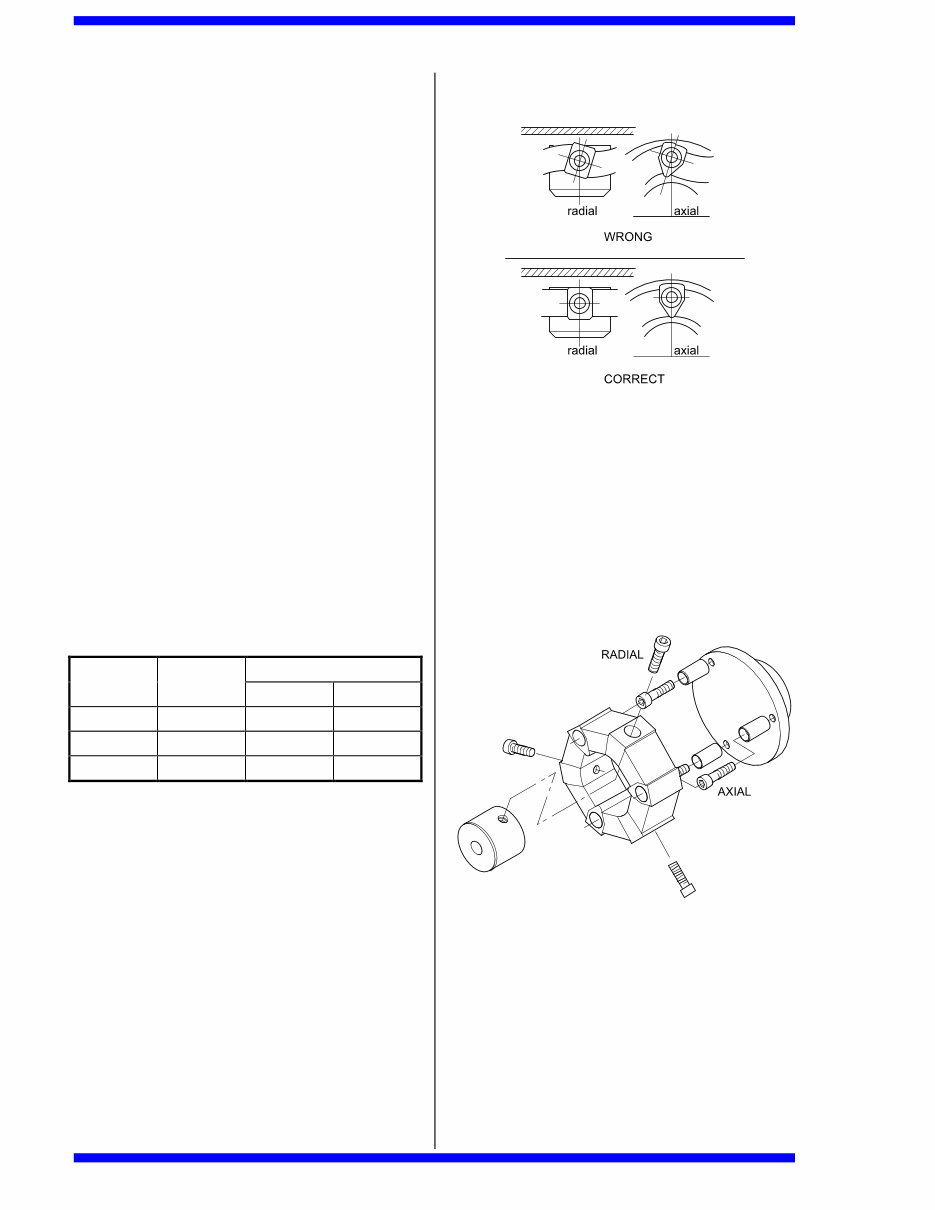
The coupling assembly consists of a central steel hub
whose outside diameter locates within a bore of a
rubber element and is secured within the element
using three cap screws that pass radially through its
outer diameter. In turn, the rubber element locates
onto three horizontal pins, equally disposed on a PCD
and each secured to the face of a steel adaptor plate
with cap screws. The cap screws securing both the
central steel hub and the horizontal pins are torque
tightened to the values shown in the table in Section
1.5.2 below.
Selwood Seltorque S150 Manual
4
The rubber element itself is free to slide on the
horizontal pins. It is therefore unnecessary to remove
the cap screws that secure the pins unless the pins
themselves have become damaged.
1.5.1 Preparation of the Centaflex Coupling
for Pump Removal
NOTE: Before commencing, mark the position of the
coupling assembly on the pump drive shaft. Pay
particular attention to the size of the gap between the
back of the rubber element and the face of the steel
adaptor plate. This gap has been factory set and is
maintained when the setscrew in the steel hub is
locked in position.
1. In order to allow the pump drive shaft to be
withdrawn from the steel hub of the coupling, it will
be necessary to loosen the setscrew located in the
outside radius of the steel hub just in front of the
rubber element. The setscrew clamps the
coupling assembly onto the top of the pump drive
shaft key and it is not necessary to completely
remove this screw.
2. Once the setscrew is loose the pump drive shaft is
free to be withdrawn from the hub of the coupling.
Note too that when the setscrew is loose the
coupling assembly is free to slide in either
direction onto the pump drive shaft or onto the
horizontal pins.
1.5.2 Centaflex Coupling Assembly
Sequence
1. The radial and axial screws connecting the rubber
element to the hubs must all be tightened to the
torque given in the table below, using a torque
wrench.
Tightening Torque
Centaflex
Size
Screw
Size
Nm mKp
16/22 M12 85 8,5
25/28 M14 140 14
30 M16 220 22
2. Tightening with a torque wrench is particularly
important. Tightening by feel will not do as
experience has proved the tightening torques in
such cases are far too low. Tightening torques
which are too low will inevitably lead to slackening
of the screws in service and consequently to the
destruction of the coupling.
3. Ensure that on tightening the screws, the
aluminium bushes in the rubber part are not
twisted at the same time, but sit straight. In order
to reduce friction between the screw head and the
aluminium part, a small amount of grease should
be applied under the head of the screw before
fitting.
4. If necessary, use a suitable tool for applying
counter pressure on the element to prevent
twisting of the rubber part during tightening of the
screws. This is particularly important with radial
screws, otherwise the cylindrical faces between
the aluminium insert and the hub will not engage
on the full area, but only on two corners. This will
inevitably lead to slackening of the screws and
subsequent destruction of the coupling. If the
coupling is supplied in a pre-assembled state do
not dismantle it, but fit it in this condition.
1.5.3 Replacement of the Steel Hub and
Rubber Element
NOTE: Once the Centaflex coupling has been
prepared in accordance with Section 1.5.1 above, it is
free to be removed from the horizontal pins on the face
of the adaptor plate.
1. If it becomes necessary to replace either the steel
hub or rubber element, the three radial caps
screws must be removed in order to separate the
two components. When removing these cap
screws it is recommended that the coupling
assembly remain on the horizontal pins for ease of
their removal.
Once the three radial screws are removed, the steel
hub can be separated from the rubber element.
Also at this stage the rubber element can be
removed from the horizontal pins of the adaptor
plate.
3. Replace the rubber element and/or steel hub as
necessary to refurbish the assembly.
4. Fit the rubber element onto the horizontal pins of
the adaptor plate.
5. Insert the steel hub into the centre of the rubber
element and align the radial mounting holes with
tapped holes in the hub.
Selwood Seltorque S150 Manual
5
6. Fit the three radial cap screws in accordance with
the instructions at Section 1.5.2.
7. The coupling assembly is now prepared for the
replacement of the pump.
8. Once the pump drive shaft is engaged in the
coupling hub bore, set the position of the coupling
assembly to that previously marked when Section
1.5.1 was performed.
9. Tighten the setscrew that locks the steel hub of
the coupling assembly to the pumps drive shaft
key.
1.6 Electric Motors
1. All electrical connections should be made through
adequately rated conductors and starters.
Isolators and other associated switchgear should
be of adequate capacity for the imposed power
loadings. All electrical equipment should be
adequately earthed.
2. Isolate the power supply before carrying out any
commissioning, servicing or maintenance work on
the pump or electric motor.
3. Where electric motors are to be operated in
hazardous or explosive atmospheres they should
be of the flameproof enclosure type appropriate to
that atmosphere.
You are requested to take such steps as are
necessary to ensure that this information is made
available to all those involved with the use of our
products. This information must be made available not
only to your own employees at their workplace, but
also to anyone who may purchase or otherwise
acquire (hire) such products for use in his own
workplace.
It is our intention constantly to review our obligations
under the Act and we will be issuing from time to time
further information with regard to the safe application,
use, inspections, and service associated with our
products.
1.7 Fitting Instructions for Fenner
Couplings (Electric Motors)
1. Adjust position of pump on chassis until the inside
faces of the coupling flanges are parallel to each
other. The distance between the faces should
measure from 24 to 29mm (15/16” to 1 1/8”).
Whilst adjusting the pump’s position, it is also
necessary to achieve alignment of the shaft
centre-lines within 1.5mm (1/16”) of each other by
laying a straight edge cross the two flanges at
several positions around their circumferences.
Fully tighten the nuts immediately the coupling
flanges are correctly aligned. Recheck alignment
after tightening.
2. The flexible coupling assembly should now be
completed. Open-out the tyre and fit over the
coupling flanges ensuring the tyre beads seat
properly on the flanges. To ensure proper
seating, it may be necessary to strike the outside
diameter of the tyre with a small mallet. When
seated there should be a gap between the ends of
the tyre of about 1/8” (3mm). Tighten clamping
ring screws in flange alternately and evenly
(approximately half a turn per screw) working
round the flange until 17lbf ft (2.35kgf m) torque is
achieved.
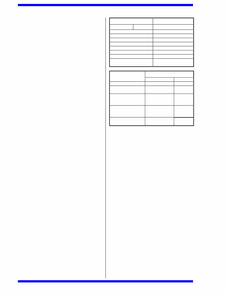
1.8 Seltorque S150 Standard Data
Capacity (max) 400M
3
/h
88,000 UK gal/h
Delivery Head (max) 21.3m
70ft
Self Priming Lift (max) 8.8m H
2
0
29ft H
2
0
Solids Size (max) 100mm
4in
Air Handling Capacity:
Single 24l/s
Prime 50ft
3
/min
Twin 48l/s
Prime 100ft
3
/min
Pump Speed 1600rpm Max
Port Size BS.4504 Table 6 150mm
6in
2 ROUTINE MAINTENANCE
Lack of routine maintenance is the most frequent
reason for the breakdown of pumps. We earnestly
advise users to ensure that at least the following
actions are taken.
1. Check these three oil levels daily:
a) Engine oil.
b) Bearing housing oil.
c) Flushing chamber oil.
2. Always drain water from the pump in cold weather
when it is not running. Drain:
a) Pump body.
b) Delivery valve chamber.
c) Both sides of air pump (4 drain taps if twin
prime).
3. Do NOT run the pump if significant quantities of
water escape through the exhaust valve of the air
pump. This pump is designed to handle moisture-
laden air, but not to pump a high percentage of
water. Refer to servicing instructions for further
advice.
4. Do NOT run the pump if malfunction is suspected
in any of its parts. In particular, it must
immediately be serviced if the level of oil in the
flushing chamber varies daily, or if the oil becomes
contaminated with the pumped fluid.
5. A hose strainer should always be fitted to the free
end of the suction line if there is a possibility of
oversized solids entering the pump. The
dimensions of rocks, pebbles, etc. must not
exceed 100mm (4"). Larger soft solids, however,
of the type found in abattoir duties, for example,
will pass freely through the pump. Refer to
Selwood Ltd if in need of advice in this connection.
Selwood Seltorque S150 Manual
6
6. As loss of prime and indeed loss of on-stream
performance can easily arise as the result of
leaking pipework joints, we recommend that all
line fittings associated with the pump should be
checked periodically for air-tightness.
7. It is most Important to use the correct fuel oil in the
engine. Make sure that it is appropriate for the
weather conditions (summer or winter) and that it
is clean and free from water and foreign matter.
Unsatisfactory running performance, excessive
wear and damage can all result from the use of an
Incorrect or contaminated fuel.
8. Periodically check the tension of all nuts and bolts,
especially those securing the engine and pump to
the chassis.
9. Pump servicing must always be carried out in
accordance with the instructions given in this
manual. Only components supplied and approved
by Selwood Ltd should be used. It is advisable to
hold a small stock of spare parts to cover
breakdown circumstances. The Company will be
pleased to give advice in this connection.
10. Engine servicing must always be carried out in
accordance with the instructions given in the
manufacturer's manual. Do not hesitate to contact
Selwood Ltd if the need for further advice arises.
11. Please contact Selwood Ltd in the event of
experiencing difficulty when servicing. The
company will also be very pleased to give advice
in connection with the machine's installation,
operation and maintenance.
12. All practical work must be carried out in
compliance with the Health and Safety at Work
Act, 1975. Always start the engine in accordance
with the manufacturer's instructions.
NOTE: If the above advice is followed, the likelihood
of an expensive break down will be greatly diminished.
The pump should give a long and trouble free life if
these measures are put into effect.
3 LUBRICATION AND
FASTENING TORQUES
3.1 Pump Lubrication
It is most important to maintain the correct levels of oil
in the flushing chamber and bearing housing, and to
ensure that the oil is of the recommended quality and
is free from contamination. Selwood recommend the
use of the following BP/Castrol products, which should
be applied as per the following table. In some
territories, the following grades may be known under
differing trade names, please contact Selwood if
problems occur in identifying the correct product.
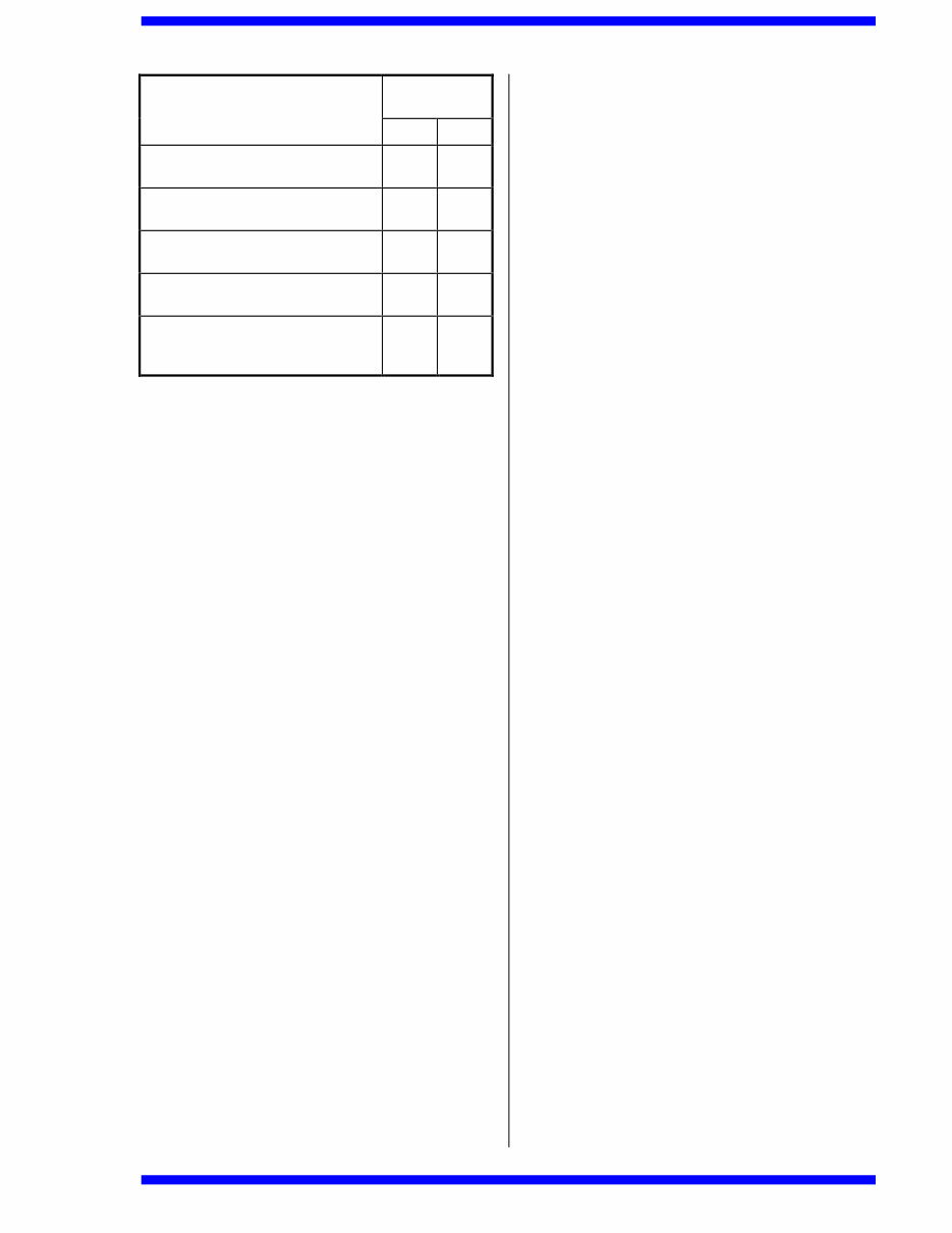
COMPONENT BP GRADE
ENGINES Vanellus C5 Global
Bearing Housing C5 Global
Flushing Chamber C5 Global
Actuator Bore Castrol Rustilo 431
Impeller Bore Castrol Rustilo 431
Paper Gaskets BP Energrease LS-EP2
Axle Shafts BP Energrease LS-EP2
Axle Pivot Assembly BP Energrease LS-EP2
M10 Screws - Port Plate
to Diffuser
Castrol Optimoly Paste
HT
DRAIN INTERVAL
COMPARTMENT
HOURS MONTHS
Engine Sump 250
Bearing Housing
Flushing Chamber
250 – 500
Actuator Bore
Impeller Bore
Shaft Sleeve Bore
ON ASSEMBLY
Paper Gaskets
Axle Shafts
Axle Pivot Assembly
ON ASSEMBLY
M10 Screws - Port
Plate to Diffuser
ON ASSEMBLY
3.1.1 Commissioning Period
Drain both pump chambers and engine within 100-150
running hours of commissioning either a new, or rebuilt
pump, and refill with new oil to level plugs.
Flushing chamber capacity about 2.3litres (4 pints).
Bearing housing capacity about 3.5litres (6¼ pints).
Engine sump – Refer to Engine Instruction Book.
3.1.2 After Commissioning Period
If the pump is driven by a diesel engine, the oil in both
pump chambers should be drained and renewed
simultaneously with the time schedule laid down by the
engine manufacturer. This will usually require the
pump oils to be drained and replaced every 250
running hours. Under no circumstances should the
period for the pump exceed 500 running hours.
3.2 Fastening Torques
Failure to tighten threaded fasteners correctly can
easily lead to assembly breakdown. It is very
important, therefore, when carrying out the instructions
in this manual, to achieve the appropriate tensioning
torques. In some cases, specific requirements are
described in the instructions, which must always be
implemented. The following torques, in particular,
must be applied.
Selwood Seltorque S150 Manual
7
Tightening
Torques
Item
lbft kgf m
(F29)(F30) M16 Pump/Engine/Fuel
Tank to Chassis Fixings
180 25
(D36) Actuator Cap Screw
0015975000
60 8.3
(A22) Cap Screw M12
9005120552
60 8.3
(C01) Impeller Screw
9000160402
80 11
Air Pump Drive rod (D37) to Small
End of Connecting Rod (D26) - M8
Fixing (D27) to (D38)
21 2.9
4 CONDITIONS OF WARRANTY
For a period of six months from delivery of any
Selwood pump to the first user thereof, or twelve
months from the despatch of any such pump by
Selwood, whichsoever period is the shorter, Selwood
will repair or, at its option, replace any component
which in the opinion of Selwood has failed due to
defective workmanship or materials.
This warranty does not apply to:
a) the driver or any accessories or proprietary fittings
whatsoever;
b) any pump which, in the opinion of Selwood, has
been altered, used, maintained, serviced or stored
otherwise than in accordance with Selwoods'
instructions and professional practice;
c) any pump from where the serial numbers have
been removed or altered;
d) fair wear and tear;
e) consequential loss or damage.
5 MAJOR SERVICING
5.1 Air Pump Maintenance
5.1.1 Delivery and Suction Valves (A07)
Failure of the pump set to prime quickly or to discharge
the expected volume of air, may simply be due to faulty
valve operation.
To inspect and service, proceed as follows:
1. Remove air hose (single prime item (A01), twin
prime items (A39/40)) from suction valve box
(A03/A41), after loosening relevant hose clips
(A02).
2. Note the orientation of the suction valve box (A03)
and exhaust cover (A04) before commencing.
Remove exhaust cover (A04) and suction valve
box (A03) by releasing nuts (A05) and spring
washers (A06).
NOTE: The above actions allow the condition of the
two valve rubbers (A07) to be checked. Do NOT
attempt to remove valve studs (A08). If valve rubbers
are damaged, replace with new components. Pull old
valves off stud heads, and discard.
3. Check and, if necessary, clean valve seats in
outer pump body (A15) and valve box (A03).
Smear heads and grooves of studs with soft soap
and push on new valves ensuring that they seat
correctly.
4. The valve assemblies can now be replaced by
reversing Instructions 1 and 2 of this procedure. It
is advisable to fit new gaskets (A30).
5.1.2 Actuator Valve (A16)
Another reason for the pump set failing to prime
efficiently or to handle the expected volume of air,
could be malfunction of the actuator valve (A16).
To inspect and service, proceed as follows:
1. Remove nuts (A11), spring washers (A12),
washers (A13) and screws (A14), allowing outer
pump body (A15) to be removed complete with
attached delivery valve assembly. The actuator
valve (A16) may now be examined. If it fails to
seat efficiently on actuator (A20) or is in any way
damaged, it should be pulled off the actuator nut
and discarded.
2. Whilst the actuator valve (A16) is removed, it is
advisable to examine the condition of the valve
seat in the actuator (A20), and also to check the
security of the actuator screw (D36). This should
be checked and tightened to 60lbf ft (8.3kgf m)
torque.
3. To replace actuator valve (A16):
a) Smear soft soap on the conical end and
groove of actuator screw (D36).
b) Ease new valve rubber into position ensuring
that it seats correctly.
NOTE: It is advisable to examine the condition of
actuator seal (A18) whilst it is exposed. Refer to
Section 5.1.3 Actuator Seal (A18) for servicing
instructions.
4. To replace outer pump body assembly, fit and
evenly tighten screws (A14), washers (A13),
spring washers (A12) and nuts (A11), by
sequentially turning each screw a small amount
until they are all fully tensioned.
NOTE: It is important that the outer diameter of the
actuator seal (A18) should be evenly clamped.
5.1.3 Actuator Seal (A18)
A further reason for the pump set failing to prime
efficiently or to handle the expected volume of air,
could be a faulty actuator seal (A18).
To inspect and service, proceed as follows:
1. Remove outer pump body (A15) complete with
delivery valve assembly. Remove actuator screw
(D36).
Selwood Seltorque S150 Manual
8
2. Set actuator to top dead centre (maximum
distance from inner pump body), by rotating
engine shaft with starting handle. Using a tool that
will not cut the rubber (such as a blunt
screwdriver) and a lubricant (soap solution),
remove actuator seal (A18) by prising it from the
inner pump body (A19).
3. Remove actuator (A20) complete with seal from
drive rod (D37).
4. To renew actuator seal (A18):
a) Remove the failed component from the
actuator.
b) Insert firstly one side and then the other into
the actuator groove, using a blunt tool that will
not cut the rubber.
NOTES: The seal is handed and will not enter the
inner pump body (A19) if fitted the wrong way round.
The correct assembly position for actuator seal (A18)
is with the smaller diameter of its conical outer surface
towards the inner pump body (A19). It will be seen
that the housing in the body is tapered in the same
direction as the external surface of the seal.
5. At this stage it is advisable to examine the
condition of actuator neck seal (A21). This
component should be replaced if any splits are
evident on its visible surface. Refer to Section
5.1.4 Actuator Neck Seal (A21).
6. Smear soft soap on the outside section of new
actuator seal (A18). Lightly grease actuator bore.
Position actuator/seal assembly on drive rod
(D37), locate actuator screw (D36) and tighten to
60lb ft (8.3kgf m) torque.
7. Replace actuator valve if removed (A16) first
smearing soft soap on the conical end and groove
of actuator screw (D36). The new valve should be
eased into position by hand.
8. Before fitting outer pump body (A15), reciprocate
the actuator by fitting and rotating the engine's
starting handle about ten times to encourage
centralisation of the connecting rod bearings.
During this procedure, the actuator seal (A18) is
likely to rotate slightly in the inner pump body
(A19). Stop shaft rotation when actuator is at
bottom dead centre (minimum distance from inner
pump body).
9. Seat outside section of actuator seal in inner
pump body recess by gently tapping with a non-
metallic mallet.
10. Replace outer pump body assembly, and fit and
evenly tighten screws (A14) washers (A13) spring
washers (A12) and nuts (A11), by sequentially
turning each screw a small amount until they are
all fully tightened. It is important that the outside
diameter of the actuator seal (A18) should be
clamped evenly.
5.1.4 Actuator Neck Seal (A21)
Another reason for the pump set failing to prime
efficiently or to handle the expected volume of air,
could be failure of the actuator neck seal (A21).
To investigate and service, proceed as follows:
1. Remove outer pump body (A15) complete with
delivery valve assembly, and actuator (A20) with
actuator seal (A18) as directed in Section 5.1.3
Actuator Seal (A18) Instructions 1 and 2.
2. Release hose clip (A02) allowing air hose to be
disconnected from suction valve box (A03).
Screws (A22) should then be removed, leaving
washers (A23) in inner pump body (A19).
3. The inner pump body can now be pulled by hand
from the bearing housing, if necessary twisting to
overcome any tendency of the seal (A21) to stick
to drive rod (D37). Remove and discard failed
seal.
4. Smear new actuator neck seal (A21) with soft
soap to assist fitting, position in inner pump body
(A19) and push both components over drive rod
(D37) using assembly tool (Part No. 0015102000)
smeared with soft soap. Check that washers
(A23) are in place, and fit and fully tighten screws
(A22). The heads of these screws should be fully
contained within the recesses in the inner pump
body.
5. Reassemble remaining components in
accordance with Section 5.1.3 Actuator Seal (A18)
Instructions 6 to 10, inclusively.
5.1.5 Drive Rod Seal Assembly and Bearing
(A25 and A28)
If oil leaks from ports in housing (A24) it is probable
that seal assembly (A25) is excessively worn. Such a
condition may also indicate that drive rod bush (A28)
should be replaced.
To inspect and service, proceed as follows:
1. Drain oil from bearing housing by removing filler
cap (D08) and drain plug (D13).
2. Remove air pump components in accordance with
Section 5.1.3 Actuator Seal (A18) Instructions 1
and 2, and to Section 5.1.4 Actuator Neck Seal
(A21) Instructions 2 and 3.
3. Being careful not to damage the flat sealing faces
of housing (A24), carefully withdraw housing
complete with its bearing and sealing components
from bearing housing (D06) and drive rod (D37).
4. Examine condition of lip and distributor seals
together with bearing. If either are worn or
damaged, we recommend that a new housing
(Part No. 0010905000) complete with seal
assembly and bearing (A28) should be ordered
and fitted. However, individual components can
be renewed in accordance with the following
instructions.
5. To replace drive rod bearing (A28) carefully
remove circlip (A26) allowing seal components to
be pushed from housing with blunt punch or drift
from bearing end. The drive rod bearing can now
be removed using bearing drift (Part No.
0015168000) and the new component pressed
into position so that one face is flush with the end
of the housing.
Selwood Seltorque S150 Manual
9
6. Ensure that seal components are assembled in
accordance with the following instructions.
a) The wiper seal (A34) is first assembled to the
drive rod seal carrier (A32) using wiper seal
insertion tool (Part No. 0010103000) ensuring
the correct orientation.
b) Then the internal distributor seal (A33) is
offered up to the bearing and seal housing
(A24) ensuring again the correct orientation
and pushed into place with the drive rod seal
carrier (Part No 0015195000) together with
wiper seal (A34)) and the whole pressed into
place with the wiper seal insertion tool (Part
No. 0010103000). Care must be exercised
when replacing circlip (A26) to ensure that the
lip of the wiper seal (A34) is not damaged by
the hand tools used. Refer to Section 6.4.
7. Before replacing bearing/seal housing assembly,
check condition of drive rod, particularly if new
bush (A28) has been fitted. If surface is
significantly worn, the drive rod should be
replaced in accordance with instructions given in
Section 5.4 Maintenance of Flushing Chamber, Air
Pump Mechanism, Drive Coupling, Drive Shaft
Bearings and Lip Seal. Specifically Section 5.4.2.
8. Assembly tool (Part No. 0015101000) must be
used when replacing bearing/ seal housing
assembly to ensure that the wiping edges of the
seal assembly (A25) are not damaged. The drive
rod must be smeared with clean oil to assist this
procedure. See Section 6.5. Gasket (A27) must
be renewed. Always use a component supplied
by Selwood Ltd. Ensure that ports in housing
(A24) are in the 3 and 9 o'clock positions.
9. Reassemble remaining pump components in
accordance with Section 5.1.4 Actuator Neck Seal
(A21) Instruction 4 and 5.1.3 Actuator Seal (A18)
Instructions 6 to 10, inclusively.
10. Replace drain plug (D13) together with sealing
washer (D14) and refill bearing housing (D06) with
clean oil to level of plug (D08) and replace plug
together with ‘O’ ring (D07). Refer to Section 3.1
Pump Lubrication for details of the oil required for
the Bearing Housing.
5.2 Separator Maintenance
5.2.1 Float (B11)
If water in significant quantities continuously passes
through the exhaust valve (A07) of the air pump, it is
probable that the float (B11) is in need of replacement.
To inspect and service, proceed as follows:
1. Disconnect air hose (A01) by loosening hose clip
(A02), and twin prime (A40) by loosening hose clip
(A02).
2. Remove nuts (A11) and washers (A12) and lift off
separator cap (B01) complete with peel
valve/upper diffuser assembly (B01) to (B21),
inclusively.
3. Examine condition of float (B11) and replace with
new component if punctured or significantly worn.
4. Check condition of peel valve rubber (B21) and
bush (B07) replacing them, if necessary, in
accordance with Section 5.2.2 Peel Valve (B21).
Also check for deposits of solids likely to interfere
with the smooth working of the float system.
5. When fitting a new float, ensure that it is securely
tightened against nut (B12). During this procedure
the float should be positioned on the rod so that
the operating plate (B15) with its associated peel
valve fasteners is just clear of the central clamp
bar screws (B16), when the float is located in the
upper diffuser cone.
6. If all components are seen to be in satisfactory
condition, replace separator cap assembly,
washers (A12) and nuts (A11). Alternately tighten
each nut a small amount to ensure that the cap is
pulled down evenly. Do not over tighten. Replace
air hose(s) and re-tension hose clip (A02).
5.2.2 Peel Valve (B21)
If significant quantities of water are discharged from
the exhaust valve (A07) of the air pump, and the float
(B11) is in satisfactory condition, it is probable that a
fault exists in the peel valve assembly.
To inspect and service, proceed as follows:
1. Remove separator cap sub-assembly (B01) to
(B21) and unscrew float (B11) and nut (B12).
2. Release screws (B09) and spring washers (B10)
to allow upper diffuser/valve assembly to be
withdrawn.
3. Remove screws (B04) and sealing washers (B05)
to allow upper diffuser (B06) to be removed from
the port plate sub-assembly.
4. Examine condition of peel valve rubber (B21) and
air ports In plate (B03) which it should completely
cover when the float is fully raised. If the rubber
does not seat correctly, is distorted, or in any way
damaged, it must be removed and discarded by
releasing screws (B16).
5. To fit new peel valve rubber (B21):
a) Carefully clean existing parts thoroughly,
especially surfaces of port plate (B03), and
clamp bars (B19) and position new rubber on
plate.
b) Assemble screws (B16), clamp bar (B19),
clamp bar seal (B20), washer (B18) and nuts
(B17) in sequence shown on drawing.
Alternately tighten each nut a small amount to
ensure that even clamping pressure is
produced. Correctly tightened nuts will not
cause the clamp bar to distort the rubber.
6. Carefully attach the ends of the valve rubber (B21)
to the operating plate (B15), noting that the
components and method of assembly are identical
to those described in Instruction 5 of this Section
except that clamp bar seal (B20) is omitted.
Again, ensure that the nuts are not over tightened.
Selwood Seltorque S150 Manual
10
7. After completing Instructions 5 and 6 of this
Section, check that the peel valve rubber is
capable of closing all of the air holes in port plate
(B03) when operating rod (B13) is square to the
plate and fully lifted.
8. Check condition of bush (B07) in upper diffuser
B06) and replace, together with clip (B08) and
nitrile washer (B37), if significantly worn.
NOTE: The operating rod (B13) is normally a slack fit
in the bush.
9. Position port plate sub-assembly on upper diffuser
(B06), fit washers (B05) after checking that they
will seal efficiently and fully tighten screws (B04).
Reassemble nut (B12) and screw float (B11) on to
operating rod and tighten securely in accordance
with Section 5.2.1 Float (B11) Instruction 5.
10. Recheck operation of peel valve rubber (B21) to
ensure that it fully covers air ports in plate (B03)
when the float is located in the upper diffuser
cone. In this position there should be a gap of
3.5 mm between the heads of the centre clamp
bar screws (B16) and the operating plate (B15). If
the dimension is incorrect, adjust position of float
on operating rod.
11. Examine condition of gasket (B02) and renew, if
necessary, before installing between port plate
(B03) and separator cap (B01). Fit spring
washers (A12) and screws (A11) each of which
should be sequentially turned a small amount until
fully tightened. Gasket (B02) must be evenly
compressed.
12. Replace separator cap sub-assembly in
accordance with Section 5.2.1 Float (B11)
Instruction 6.
5.2.3 Deposits of Solids
†‡
When handling liquids containing solids capable of
adhering to product wetted surfaces, it is advisable
periodically to check the valve system in the separator.
To inspect and service, proceed as follows:
1. Remove separator cap sub-assembly in
accordance with Section 5.2.1 Float (B11)
Instructions 1 and 2, allowing separator body
(B22) together with lower diffuser (B24), to be
lifted off the suction tube (B27).
2. Remove any deposits of scale from lower diffuser
(B24) and check condition of welds securing its
circular bottom to the perforated cylinder.
Remove any solids that may have accumulated in
the suction tube (B27), renew gasket (B25) and
reposition separator body/lower diffuser assembly
on suction tube.
3. Remove deposited materials from surfaces of
upper diffuser (B06) and note, in particular,
condition of welds securing cone and disc to
perforated diffuser body. Also examine diffuser
†
Use lower Diffuser (Part No. 00-15-038100) for sludge
handling duties. This is recognised by holes in the base as
well as around the side.
‡
Use lower Diffuser (Part No. 00-15-038000) for other
applications where no solids are present which can adhere to
the internal surfaces.
bush (B07) and operating rod (B13), and replace if
significantly worn in accordance with Section 5.2.2
Peel Valve (B21) Instructions 3 to 11. Remove all
deposited solids that would interfere with the free
movement of the mechanism, obstruct the
passage of air across the port plate holes, or
inhibit the flow of water (through the holes in the
upper diffuser, for example).
4. Once it is established that all components are in a
satisfactory condition and are free from scale,
replace separator cap sub-assembly in
accordance with Section 5.2.1 Float (B11)
Instruction 6. Any re-assembly work carried out
on the peel valve assembly should be in
accordance with Section 5.2.2 Peel Valve (B21)
commencing Instruction 1.
The fabricated separator chamber (B35) (Part No.
0015105100 is normally utilized when the pump is
fitted with Twin Prime where the larger volume allows
better separation of air from the pumped liquid.
The two top fixings attaching the separator chamber
(B35) to the pump body (C09) are located inside the
chamber necessitating (B36) M12 dome nuts and
spacer washers to protect the stud threads.
5.3 Impeller, Mechanical Seal and
Delivery Valve Maintenance
5.3.1 Impeller (C04)
Generally speaking, it is only necessary to remove the
impeller if the existing component has become
severely abraded, or if access to other rotating parts is
required.
To remove and replace, proceed as follows:
1. Remove air hose item (A01), twin prime item
(A39) and (A40) from separator cap (B01), after
loosening relevant hose clip (A02).
2. Remove nuts (A11) and washers (A12), and lift off
separator cap (B01) complete with peel
valve/upper diffuser assembly, (B01) to (B21)
inclusively.
3. Lift separator body (B22) complete with lower
diffuser (B24) off suction tube (B27) or (B35)
allowing (dome) nuts (B36) or (B29) and spring
washers (B39) or (B30) to be released.
4. Withdraw suction tube (B27) or (B35) and gasket
(B28) after removing nuts (B29) and associated
spring washers (B30).
5. Drain oil from flushing chamber by removing filler
cap assembly (D08) and drain plug (D34). The
condition of the oil will indicate whether or not the
mechanical seal has been functioning correctly. If
contamination is evident, the mechanical seal
must be replaced in accordance with Section 5.3.2
Mechanical Seal (C08).
6. Remove impeller screw (C01) and washers (C02)
and (C03), and withdraw impeller (C04) from drive
shaft (D17). To remove the screw, it will be
necessary to lock the impeller by means of a
wooden block wedged between the impeller
blades and pump body (C09).
You're Reading a Preview
What's Included?
 Lifetime Access
Fast Download Speeds
Online & Offline Access
Access PDF Contents & Bookmarks
Full Search Facility
Print one or all pages of your manual
$27.99
Selwood Seltorque S150 pump service,operating & parts manual
Viewed 99 Times Today

What's Included?
Lifetime Access
Fast Download Speeds
Online & Offline Access
Access PDF Contents & Bookmarks
Full Search Facility
Print one or all pages of your manual
$27.99

Secure transaction
What's Included?
Lifetime Access
Fast Download Speeds
Online & Offline Access
Access PDF Contents & Bookmarks
Full Search Facility
Print one or all pages of your manual
Description
The Selwood Seltorque S150 pump manual is an essential resource for anyone involved in the maintenance, operation, or repair of this equipment. Whether you are a professional mechanic or a DIY enthusiast, this manual provides comprehensive guidance for servicing and maintaining the Seltorque S150 pump.
It includes detailed information on the pump's operating principles, service procedures, and parts identification. With this manual, you can effectively troubleshoot issues, perform routine maintenance, and carry out repairs with confidence.


