

WORCESTER BOSCH GreenStar 35 HE Combi Installation And Servicing Instructions
What's Included?
Fast Download Speeds
Online & Offline Access
Access PDF Contents & Bookmarks
Full Search Facility
Print one or all pages of your manual
6 720 610 893-01.TD
Installation and Servicing Instructions
R 30/35/40 HE plus combi
Wall mounted condensing boiler for central heating and mains
fed domestic hot water
ZWBR 7-30 R 30 HE plus GC-Number: 41 311 79
ZWBR 11-35 R 35 HE plus GC-Number: 41 311 80
ZWBR 11-40 R 40 HE plus GC Number 41 311 81
6 720 611 400 GB (03.11) TD

6 720 611 400 GB (03.11)
Contents
2
Contents
Safety precautions 3
Symbols 3
1 Details of the appliance 4
1.1 EC Declaration of Conformity 4
1.2 Standard package 4
1.3 Description of appliance 4
1.4 Accessories 5
1.5 Casing dimensions 5
1.6 Layout of appliance 6
1.7 Function 7
1.8 Electrical wiring diagram 8
1.9 Technical data 9
2 Installation regulations 10
3 Installation 11
3.1 Important remarks 11
3.2 Domestic hot water 11
3.3 Sealed systems 11
3.4 Siting the appliance 12
3.5 Wall mounting frame assembly 13
3.6 Pre-piping the system 13
3.7 Fitting the appliance 14
3.8 Checking the connections 15
3.9 Flue Systems 15
3.9.1 Siting the Flue Terminal 16
3.9.2 Installation of the flue 17
3.9.3 Flue duct preparation and assembly 19
4 Electrical connections 20
4.1 Connecting the appliance 20
4.2 Connecting TR2 Room thermostat 21
4.3 Mains Voltage external controls connections 21
5 Commissioning 22
5.1 Commissioning 22
5.2 Switching the appliance on/off 23
5.3 Switching on the central heating 23
5.4 System controls 23
5.5 Setting the domestic hot water temperature and flow
rate 24
5.5.1 Domestic hot water temperature 24
5.5.2 Hot water flow rate 24
5.6 Summer mode (hot water only) 24
5.7 Frost protection 24
5.8 Pump anti-seize function 24
5.9 Fault Condition 25
6 Text Display 26
6.1 General Description 26
6.2 Programming 26
6.2.1 Deleting a setting 27
6.2.2 Resetting all parameters to their original settings 27
6.3 Menu structure 27
6.4 Setting the time/day 28
6.4.1 Setting the time and day 28
6.4.2 Holidays 28
6.5 Heating 28
6.5.1 Heating programme 28
6.5.2 Setting Economy temperature (TR2 connected) 28
6.5.3 Manual operating mode (TR2 not connected) 29
6.6 Hot water 29
6.6.1 Hot water programme 29
6.6.2 Hot water immediately 29
6.7 i Info 29
6.8 Settings 30
6.8.1 Heating (if TR 2 is connected) 30
6.8.2 Hot Water (Storage Tank, system models only) 30
6.8.3 Service 30
6.9 Individual timer programmes 30
7 Individual settings 31
7.1 Mechanical settings 31
7.1.1 Checking the size of the expansion vessel 31
7.1.2 Setting the central heating flow temperature 31
7.2 Settings on the Bosch Heatronic 31
7.2.1 General description 31
7.2.2 Setting the anti-cycle time
(Service Function 2.4) 32
7.2.3 Setting the maximum CH flow temperature (Service
Function 2.5) 32
7.2.4 Setting the heating output
(Service Function 5.0) 32
7.2.5 Constant hot water cycle time
(Service Function 6.8) 32
7.2.6 Variable pump settings
(Service Function 7.0) 32
7.3 Setting the gas/air ratio 32
8 Converting the appliance to different
gas types 33
8.1 Setting the gas/air ratio 33
8.2 Testing combustion air/flue gas at set heat output 35
8.2.1 Testing the O2 or CO2 level in the combustion air 35
8.2.2 Testing CO and CO2 35
9 Maintenance 36
9.1 Pre-Service Check List 37
9.2 Description of servicing operations 38
9.3 Replacement of Parts 41
9.3.1 PCB control board and transformer 41
9.3.2 Fan Assembly 42
9.3.3 Pump 42
9.3.4 3-way diverter valve 43
9.3.5 3-way diverter valve motor 43
9.3.6 Sensors 43
9.3.7 Gas Valve 44
9.3.8 Domestic Hot Water Heat Exchanger 44
9.3.9 Electrode assembly 44
9.3.10 Pressure gauge 44
9.3.11 Expansion vessel 44
9.3.12 Pressure Relief Valve 44
9.3.13 Burner 44
9.3.14 Flow switch 45
9.3.15 Primary Heat Exchanger 45
10 Appendix 46
10.1 Fault Codes 46
10.2 Short parts list 47
10.3 Heating/hot water output settings R 30 HE N.G. 48
10.4 Heating/hot water output settings R 30 HE L.P.G 48
10.5 Heating/hot water output settings R 35 HE N.G. 48
10.6 Heating/hot water output settings R 35 HE L.P.G 48
10.7 Operational Flow diagrams 49
10.7.1 Domestic hot water function 49
10.7.2 Central heating function 5010.7.2Central heating
function 50

6 720 611 400 GB (03.11)
Safety precautions
3
Safety precautions
If you smell gas
B Turn off gas service cock at the meter.
B Open windows and doors.
B Do not operate any electrical switches.
B Extinguish any naked flames.
B Telephone your gas company.
If you smell fumes from the appliance
B Switch off appliance (see page 23).
B Open windows and doors.
Fitting and modifications
B Fitting of the appliance or any controls to the appli-
ance may only be carried out by a competent engi-
neer in accordance with the Gas Safety (Installation
and Use) Regulations 1998.
B Flue systems must not be modified in any ways other
than as described in the fitting instructions.
B This appliance is for use on sealed primary systems only.
Maintenance
B The user is recommended: to have the system
regularly serviced in order to ensure that it functions
reliably and safely.
B Use only original spare parts!
Combustible materials
B Do not store or use any combustible materials
(paper, thinners, paints etc.) in the vicinity of the
appliance.
Health and safety
B This appliance contains no asbestos products.
B There is no potential hazard due to the appliance
being electrically unsafe.
B There are no substances used in the construction
that are a potential hazard in relation to the COSHH
Regulations (Control of Substances Hazardous to
Health Regulations 1988).
Combustion air/Ambient atmosphere
B The combustion air/ambient atmosphere should be
kept free of chemically aggressive substances (e.g.
halogenated hydrocarbons which contain chlorine or
fluorine compounds). This will prevent corrosion.
Instructions to the customer
B Explain to the customer how the appliance works and
how to operate it.
B Advise the user that he/she must not make any modi-
fications to the appliance or carry out any repairs on it.
B These instructions are to be left with the user or at
the Gas meter.
B Important: These instructions apply in the UK only.
Unpacking
IMPORTANT HANDLING INSTRUCTIONS
B Two people should transfer the packaged appliance
from the van to the point of installation
B Open the top of the carton, remove and place the
component tray and both side bars of the wall mount-
ing frame to one side
B Lie the packaged appliance on its back. (The back
has “TRUCK HERE” printed on the carton)
B One person firmly holds the packaging while the
other straddles the boiler and slides it from the pack-
aging
B Two persons are then required to lift one end and
stand the appliance upright with the flue at the top
Additional requirements for roof space instal-
lation
B Two people should use two step ladders and share
lifting the unpacked boiler up to the loft hatch
B Where the boiler enters the loft space, tilt and slide
the boiler on its back to the point of installation
Check the contents against the packing list.
Symbols
Safety instructions in this document
are identified by a warning-triangle sym-
bol and are printed on a grey back-
ground.
i
Notes containing important information
are identified by the symbol shown on the
left. They are bordered by horizontal lines
above and below the text.

6 720 611 400 GB (03.11)
4
Details of the appliance
1 Details of the appliance
1.1 EC Declaration of Conformity
This appliance is in accordance with the applicable
requirements of the Gas Appliance Directive, Boiler Effi-
ciency Directive, Electromagnetic Compatibility Direc-
tive and the Low Voltage Directive.
1.2 Standard package
• Gas condensing combination boiler for central heat-
ing and domestic hot water
• Control panel cover
• Wall mounting frame
• Fixings (screws etc.)
• Set of documentation for appliance
• Pre-plumbing manifold
• Condensate drain pipe
• Filling loop.
1.3 Description of appliance
• Wall-mounted appliance.
• Natural gas models are low-emission appliances
• Multi function display
• Bosch Heatronic control system with integrated text
display for service functions and faults
• 3-channel - digital timer for one heating circuit
• Variable pump
• Automatic ignition
• Modulating control
• Full safety systems incorporating Bosch Heatronic
with flame ionisation monitoring, solenoid valves and
temperature sensors
• Concentric flue/air duct with testing point for
CO
2
/CO
• Regulated speed fan
• Pre-mix burner
• Temperature control for central heating
• Temperature sensor in domestic hot water
• Safety temperature limiter in 24 V electrical circuit
• Relief valve, pressure gauge, expansion vessel, Auto
air vent
• Flue gas temperature limiter (105 °C)
• Hot water priority circuit
• Motorised 3-way valve
• Plate-type heat exchange
• Condensate Trap.
PIN CE-0085 BL0507
Category UK II
2H 3P
Appliance Type C
13
, C
33
Table 1
6 720 611 400 GB (03.11)
Details of the appliance
5
1.4 Accessories
• Standard horizontal flue kit at 100 mm outside
diameter for flues up to 4 m in length (3.5m for the R
40 HE).
• Flue duct kits for horizontal (125 mm outside
diameter) for flue lengths up to 13m or 10m (R 35 &
40 HE) and vertical flue systems for flue lengths up
to 13.7m or 10.7m (R 35 & 40 HE). Fitting instruc-
tions are sent with these kits.
• TR2 Room Temperature Controller..
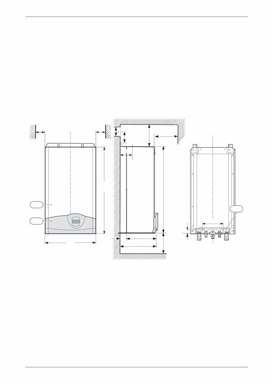
1.5 Casing dimensions
Fig. 1
13 Manifold assembly
101 Outer case
103 Facia cover
X Standard Concentric Horizontal Flue System: min. 160 mm
Alternative Concentric Flue System: min. 220 mm
Y Standard Concentric Horizontal Flue System: 40 mm
Alternative Concentric Flue System: 70 mm
Z Standard Concentric Horizontal Flue System: 105 mm
Alternative Concentric Flue System: 130 mm
* For servicing the appliance
Note: Horizontal flue only: dimension X may need to increase due
to the incline of the flue.
6 720 610 599 - 01.TD
200
30
13
395
360
850
35
X
120
Y
Z
200
*
* 600
min .
10*
min .
440
850
101
103
10*
6 720 611 400 GB (03.11)
6
Details of the appliance
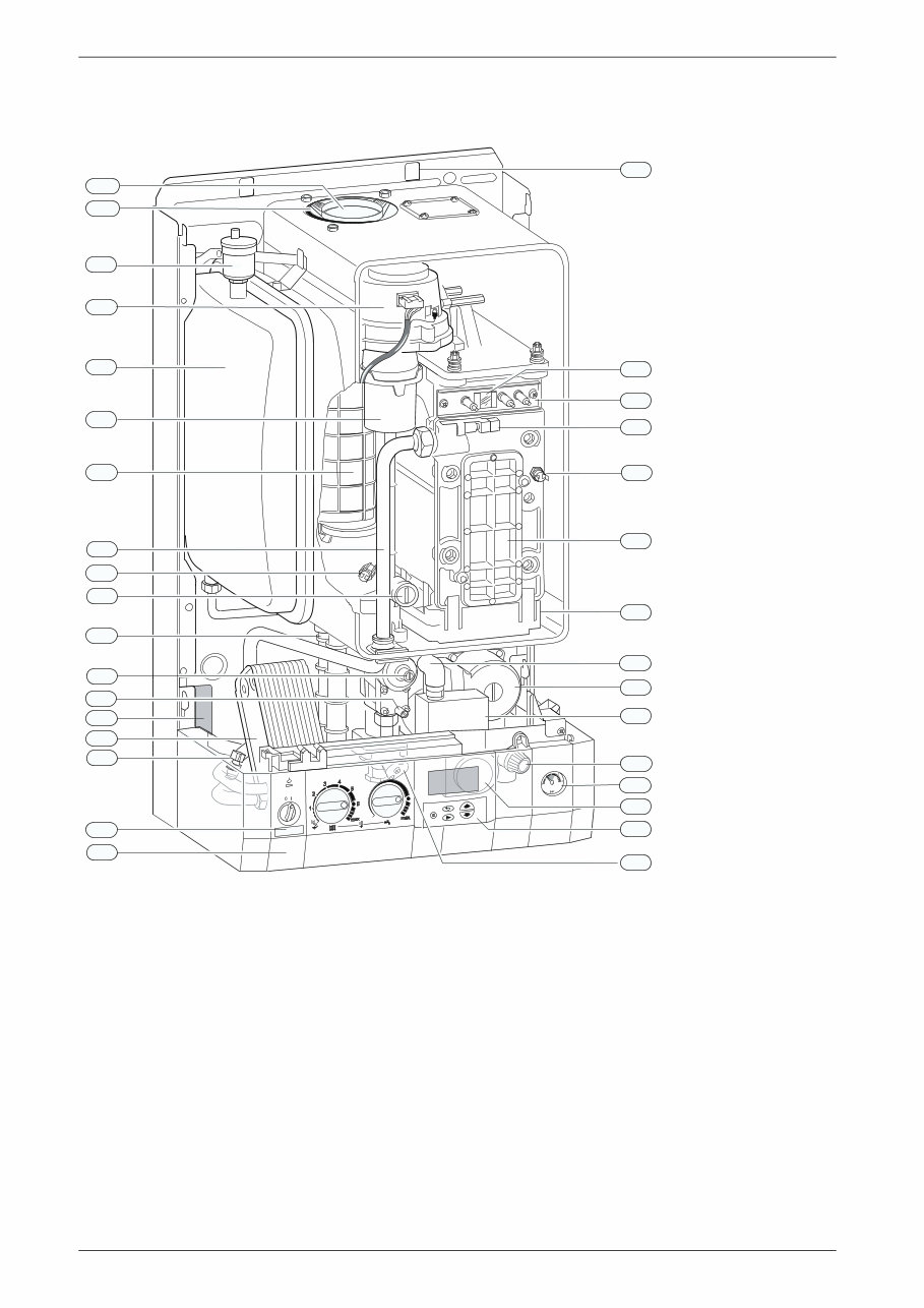
1.6 Layout of appliance
Fig. 2
4 Heatronic control
6 Heat exchanger safety temperature limiter
6.1 Hot water NTC sensor
7 Testing point for gas supply pressure
8.1 Pressure gauge
9 Flue gas temperature limiter
15 Relief valve
18 Pump
20 Expansion vessel
27 Automatic air vent
29 Air gas Mixer unit
32.1 Electrode assembly
36 Temperature sensor in CH flow
43 CH flow
63 Adjustable gas flow restrictor
64 Adjusting screw for min. gas flow volume
88 3-way valve (combi)
98 DHW flow switch (combi)
102 Inspection window
120 Fixing points
221.1 Flue duct
221.2 Combustion air intake
226 Fan assembly
295 Appliance type sticker
271 Flue duct
355 Plate-type domestic hot water heat exchanger
358 Condensate trap
396 Hose Condensate trap
400 Text display
415 Cover plate for cleaning access
416 Condensate collector
418 Data plate
423 Siphon
6 720 610 599 - 00.TD
29
98
102
226
271
416
20
43
9
63
358
64
7
355
6.1
4
415
6
36
32.1
295
8.1
18
27
88
15
120
418
400
396
423
221.1
221.2
6 720 611 400 GB (03.11)
Details of the appliance
7
1.7 Function
Fig. 3
4 Bosch Heatronic control
6 Temperature limiter, heat exchanger
6.1 Hot water NTC sensor
7 Testing point for gas supply pressure
8.1 Pressure gauge
9 Flue gas temperature limiter
13 Manifold
15 Safety valve
18 Central heating pump
20 Expansion vessel
26 Charging valve
27 Automatic vent
29 Mixer unit
29.1 Bi-metallic thermostat for combustion air compensation
30 Burner
32 Flame sensing electrode
33 Igniter electrode
35 Heat exchanger with cooled combustion chamber
36 Temperature sensor in CH flow
43 CH flow
44 Hot water flow
45 Gas
46 Cold water inlet
47 CH return
52 Solenoid valve 1
52.1 Solenoid valve 2
55 Filter
56 Gas valve CE 427
57 Main valve disc
61 Reset button
63 Gas flow restrictor, adjustable for max. gas flow volume
64 Adjusting screw for min. gas flow volume
69 Control valve
84 Motor
88 3-way valve
90 Venturi
91 Pressure relief valve
93 Water flow regulator
94 Diaphragm
95 Pushrod with switch cam
96 Microswitch
97 Valve for hot water flow volume
98 Water valve
221 Flue duct
226 Fan
229 Air box
317 Display
355 Plate-type heat exchanger
358 Condensate trap
400 Text display
423 Siphon
443 Diaphragm
6 720 610 597-
03.2O
42
3
J
33 29 30 226 229 26
6
36
29.1
63
15
45 47
20
43 44 46 13
8.1
84
90
97 98
93
94
95
96
91
69
64
57
52.1
56 52
55
7
355
M
358
18
88
max max
1
2
3 4
5
E
ECO
0
317 61 4 400
32
9
35
221
J
27
6.1
6 720 611 400 GB (03.11)
8
Details of the appliance
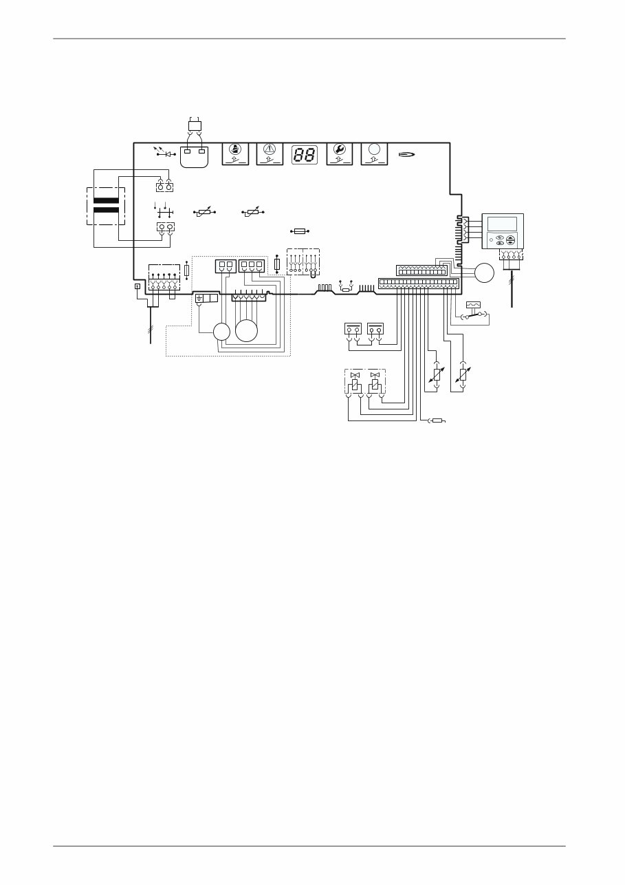
1.8 Electrical wiring diagram
Fig. 4
4.1 Ignition transformer
6 Temperature limiter, heat exchanger
6.1 Hot water NTC sensor
9 Flue gas temperature limiter
18 Pump
32 Flame sensing electrode
33 Ignition electrode
36 Temperature sensor in CH flow
52 Solenoid valve 1
52.1 Solenoid valve 2
56 Gas valve CE 427
61 Reset button
84 Motor, 3-way valve
96 Microswitch, hydraulic switch
135 Master switch
136 Temperature control for CH flow
151 Fuse, slow 2.5 A, AC 230 V
153 Transformer
161 Link
226 Fan
300 Code plug
302 Earth connection
310 Temperature control for hot water
312 Fuse, slow T 1,6 A
313 Fuse, slow T 0,5 A
317 Digital display
328 Terminal block for AC 230 V Mains supply
328.1 Link
363 Indicator lamp for burner
364 Indicator lamp for power supply
365 “Chimney sweep” button
366 Service button
367 ECO button
400 Text display
422 Connecting TR2
6 9
32
33
36
52.1 52
56
61
230 V
135
25 V
230V/AC
153
136
151
124 789
161
M 226
300
LN Ls Ns
328
LR
302
310
312
313
317 363 364 365 366
ECO
367
4.1
328.1
6.1
18
84
96
M
400
4 3 F
M
6 720 610 602 - 02.1O
mains supply
422
o - orange g - green bl - black r - red p - purple
r
r
bl
bl
bl
bl bl
o
o
o
o
g
g
p
p
p
6 720 611 400 GB (03.11)
Details of the appliance
9
1.9 Technical data
Units
R 30 HE
NG
R 30 HE
Propane
R 35 HEi
NG
R 35 HE
Propane
R 40 HE
NG
R 40 HE
Propane
Max. rated heat output net 40/30°C central heating
Max. rated heat output net 50/30°C central heating
Max. rated heat output net 80/60°C central heating
kW
kW
kW
31.2
30.9
29.2
31.2
30.9
29.2
37.5
37.1
35.1
37.5
37.1
35.1
41.4 41.4
41.4 41.4
39.1 39.1
Max. rated heat input net kW 29.5 29.5 35.5 35.5 40.0 40.0
Min. rated heat output net 40/30°C
Min. rated heat output net 50/30°C
Min. rated heat output net 80/60°C
kW
kW
kW
8.4
8.3
7.4
11.6
11.4
10.5
12.9
12.8
11.4
16.2
16.1
14.3
12.9 16.2
12.8 16.1
11.4 14.3
Min. rated heat input net kW 7.6 10.8 11.8 14.8 11.8 14.8
Max. rated heat output net, domestic hot water kW 29.2 29.2 35.1 35.1 39.1 39.1
Max. rated heat input net, domestic hot water kW 29.5 29.5 35.5 35.5 40 40
Maximum gas flow rate – After 10 minutes from lighting
Natural gas G20 (CVnet 34.02 MJ/m
3
) m
3
/h
3.1 3.7
4.2
LPG (CVnet 88 MJ/m
3
)
kg/h 2.3
3.2
Gas supply pressure
Natural gas G20 (CVnet 34.02 MJ/m
3
)
mbar 20 - 20 -
20 -
LPG (CVnet 88 MJ/m
3
)
mbar - 37 - 37
- 37
Expansion vessel
Charge pressure bar 0.75 0.75 0.75 0.75 0.75 0.75
Total capacity l 10 10 10 10 10 10
Hot water specifications
Hot water flow rate @ 35° rise l/min 12.1 12.1 14.6 14.6 16.4 16.4
Outlet temperature range °C 40 - 60 40 - 60 40 - 60 40 - 60 40 - 60 40 - 60
Max. permissible water supply pressure bar 10 10 10 10 10 10
Min. inlet pressure for maximum flow rate bar 1.2 1.2 1.2 1.2 1.2 1.2
Specific flow rate @ 30°C l/min 13.3 13.3 16.0 16.0 18.0 18.0
Flue
Flue gas temp. 80/60°C, rated/min. load °C 67/55 67/55 87/58 87/58 87/58 87/58
Flue gas temp. 40/30°C, rated/min. load °C 43/32 43/32 65/43 65/43 65/43 65/43
Residual delivery pressure (inc. pressure drop in air
intake duct)
Pa 80 80 100 100 100 100
CO
2
level at max. rated heat output
CO
2
level at min. rated heat output
%
%
9.2
8.8
10.8
10.5
9.2
9.2
11.0
11.0
9.2
9.2
10.8
10.8
NO
x
-class 5 5 5 5
5 5
SEDBUK figure Band A A A A A A
Condensate
Max. condensation rate (t
R
= 30°C) l/h 2.5 2.5 3.0 3.0
3.5 3.5
pH-value, approx. pH 4.8 4.8 4.8 4.8 4.8 4.8
General Data
Electrical power supply voltage AC ... V 230 230 230 230 230 230
Frequency Hz 50 50 50 50 50 50
Max. power consumption W 125 125 152 152 183 183
Noise output level dB(A) 37 37 40 40 42 42
Appliance protection rating IP X4D X4D X4D X4D X4D X4D
Max. CH flow temperature °C nom. 90 nom. 90 nom. 90 nom. 90 nom. 90 nom.90
Max. permissible operating pressure (CH) bar 2.5 2.5 2.5 2.5 2.5 2.5
Permissible ambient temperatures °C 0 - 50 0 - 50 0 - 50 0 - 50 0 - 50 0 - 50
Nominal capacity of appliance l 3.75 3.75 3.75 3.75 3.75 3.75
Weight (excluding packaging) kg 46 46 46 46 46 46
Table 2
6 720 611 400 GB (03.11)
10
Installation regulations
Condensate analysis, mg/l
Flue system
Elbow - 90 ° Equivalent length 2 m
Bend - 45 ° Equivalent length 1m
Gas supply
Domestic water performance
2 Installation regulations
Gas Safety (Installation & Use) Regulations 1998: All
gas appliances must be installed by a competent per-
son. Failure to install correctly could lead to prosecu-
tion.
The manufacturers notes must not be taken, in any way,
as overriding statutory obligations.
The appliance must be installed in accordance with the
current IEE Wiring Regulations, local Building Regula-
tions, Building Standards (Scotland) (Consolidation),
bye-laws of the local Water Company, Health and
Safety Document 635 (Electricity at Work Regulations
1989) and any other local requirements.
Product Liability regulations indicate that, in certain cir-
cumstances, the installer can be held responsible, not
only for mistakes on his part but also for damage result-
ing from the use of faulty materials. We advise the
installer to avoid any risk by using only quality approved
branded fittings.
The relevant British Standards should be followed i.e.
• BS 6798: Specification for the installation of gas
fired hot water boilers of rated input not exceeding
60kW
• BS 5449: Central Heating for Domestic Premises
• BS 5546: Installation of gas hot water supplies for
domestic purposes
• BS 5440:1: Flues and ventilation for gas appliances
of rated input not exceeding 70 kW (net): Flues
• BS 5440:2: Flues and ventilation for gas appliances
of rated input not exceeding 70 kW (net): Air
Supply
• BS 6891: Installation of low pressure gas pipework
installations up to 28mm (R1).
• BS 7074:1: Code of practice for domestic heating
and hot water supply
• BS 7671: Requirements for Electrical Installation.
These instructions must be followed.
Ammonium 1.2 Nickel 0.15
Lead ≤ 0.01 Mercury ≤ 0.0001
Cadmium ≤ 0.001 Sulphate 1
Chromium ≤ 0.005 Zinc ≤ 0.015
Halogenated
hydrocarbons ≤ 0.002
Tin ≤ 0.01
Hydrocarbons 0.015 Vanadium ≤ 0.001
Copper 0.028 pH-value 4.8
Table 3
HORIZONTAL 100 mm – Standard FLUE SYSTEM
Overall Diameter of Duct mm 100
Max. 4 m
(R30 & 35 HE)
Max 3.5m
(R40 HE)
Flue Terminal / Duct
Assembly Length
mm 600
Extension Duct Length mm 1000
Table 4
HORIZONTAL 125 mm FLUE SYSTEM
Overall Diameter of Duct mm 125 Max. 13 m
(R30HE)
Max. 10m (R35 &
40 HE)
Flue Terminal / Duct
Assembly
mm 1030
Table 5
VERTICAL 100mm FLUE SYSTEM
Overall Dia. of Duct mm 100 Excl. terminal:
Max. 6.4m (R30
& 35 HE)
Max. 5.5m
(R40HE)
Flue Terminal / Duct
Assembly Length
mm 1140
Table 6
VERTICAL 125 mm FLUE SYSTEM
Overall Dia. of Duct mm 125 Excl. terminal: Max.
13.7 m (R30HE)
Max. 10.7 m
(R35 & 40HE)
Flue Terminal / Duct
Assembly
mm 1365
Table 7
Total length of gas supply pipe
(metres)
Pipe diameter
(mm)
3 6 9
Gas discharge rate (m
3
/h)
8.7 5.8 4.6 22
18.0 12.0 9.4 28
Table 8
R 30
HE
R 35
HE
R 40
HE
Domestic
Water Flow
Rate l/min
Tempera-
ture Rise
30 °C 14.2 17.0
19.2
Tempera-
ture Rise
35 °C 12.1 14.6
16.4
Tempera-
ture Rise
40 °C 10.6 12.8
14.4
Maximum Mains pressure bar 10.0 10.0
10
Minimum Mains pressure bar 0.2 0.2
0.2
Table 9
You're Reading a Preview
What's Included?
Fast Download Speeds
Online & Offline Access
Access PDF Contents & Bookmarks
Full Search Facility
Print one or all pages of your manual
$28.99
Viewed 14 Times Today


Secure transaction
What's Included?
Fast Download Speeds
Online & Offline Access
Access PDF Contents & Bookmarks
Full Search Facility
Print one or all pages of your manual
$28.99
Get detailed information on how to fix or maintain your boiler with the GAM Boiler Manuals. These manuals are model-specific and not generic, making them useful for both professional mechanics and DIY enthusiasts. By having this manual, you can prevent yourself from being misled by unethical repairmen and gain a full understanding of your device.
The manual contains detailed information for every owner and user alike, making it a valuable resource for anyone looking to maintain or repair their boiler. It will be made available instantly upon completion of payment, eliminating the need to wait for unreliable postal delivery. Additionally, you can print only the pages you need, making it a convenient and practical resource.


