SAFETY PRECAUTIONS MAINTENANCE AND REPAIR • The Service Manuals are updated on a regular basis, but may not reflect recent design changes to the product. Updated technical service information may be available from your local authorized Yale® dealer. Service Manuals provide general guidelines for maintenance and service and are intended for use by trained and experienced techni- cians. Failure to properly maintain equipment or to follow instructions contained in the Service Manual could result in damage to the products, personal injury, property damage or death. • When lifting parts or assemblies, make sure all slings, chains, or cables are correctly fastened, and that the load being lifted is balanced. Make sure the crane, cables, and chains have the capacity to support the weight of the load. • Do not lift heavy parts by hand, use a lifting mechanism. • Wear safety glasses. • DISCONNECT THE BATTERY CONNECTOR before doing any maintenance or repair on electric lift trucks. Discon- nect the battery ground cable on internal combustion lift trucks. • Always use correct blocks to prevent the unit from rolling or falling. See HOW TO PUT THE LIFT TRUCK ON BLOCKS in the Operating Manual or the Periodic Maintenance section. • Keep the unit clean and the working area clean and orderly. • Use the correct tools for the job. • Keep the tools clean and in good condition. • Always use YALE APPROVED parts when making repairs. Replacement parts must meet or exceed the specifications of the original equipment manufacturer. • Make sure all nuts, bolts, snap rings, and other fastening devices are removed before using force to remove parts. • Always fasten a DO NOT OPERATE tag to the controls of the unit when making repairs, or if the unit needs repairs. • Be sure to follow the WARNING and CAUTION notes in the instructions. • Gasoline, Liquid Petroleum Gas (LPG), Compressed Natural Gas (CNG), and Diesel fuel are flammable. Be sure to follow the necessary safety precautions when handling these fuels and when working on these fuel systems. • Batteries generate flammable gas when they are being charged. Keep fire and sparks away from the area. Make sure the area is well ventilated. NOTE: The following symbols and words indicate safety information in this manual: WARNING Indicates a hazardous situation which, if not avoided, could result in death or serious injury. CAUTION Indicates a hazardous situation which, if not avoided, could result in minor or moderate injury and property damage. On the lift truck, the WARNING symbol and word are on orange background. The CAUTION symbol and word are on yellow background.
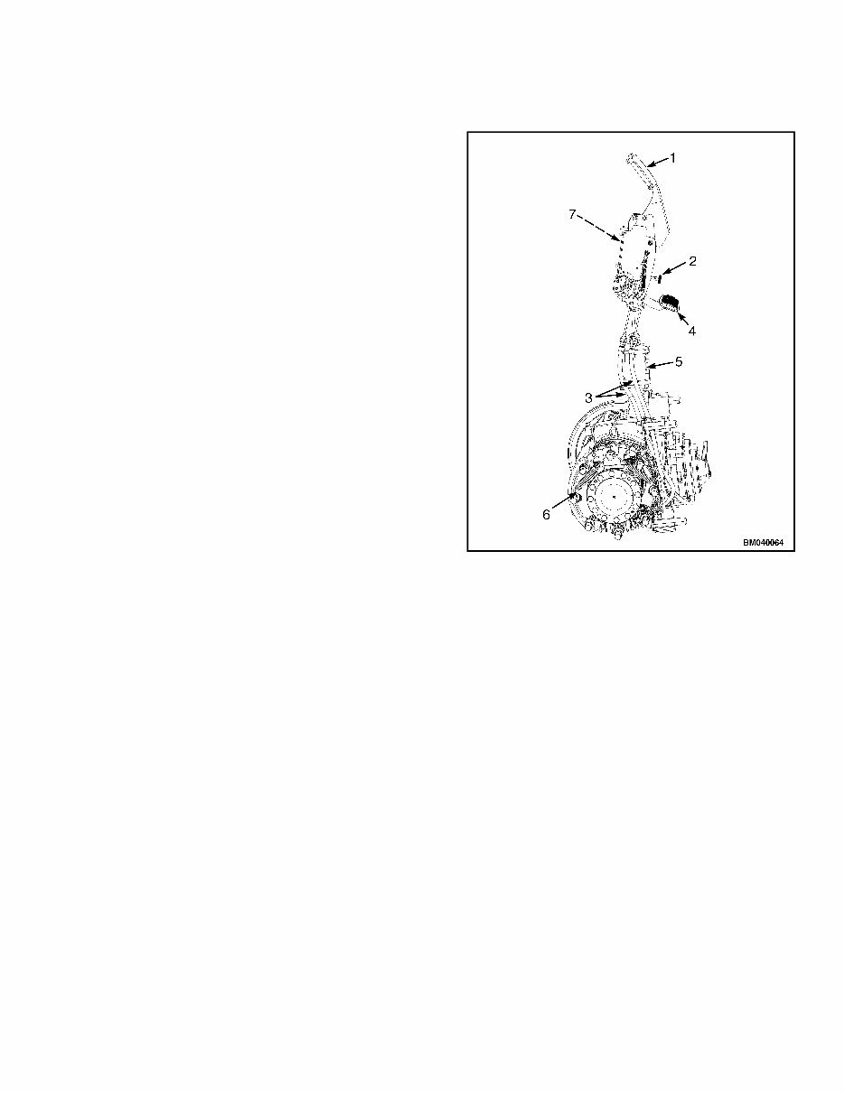
1800 YRM 1247 General General DRY BRAKE SYSTEM NOTE: The dry brake system is used only on lift truck models • GLC40, 45, 55VX; GLC55SVX; (GC/GLC080, 100, 120VX; GC/GLC080, 100VXBCS; GC/GLC120SVX; GC/GLC120VXPRS) (E818) • GLP/GDP40VX5/VX6; GLP/GDP45SVX5, GLP/ GDP45VX6, GLP/GDP50-55VX (GP/GLP/GDP080, 090, 100, 110, 120VX) (F813, G813, H813) This section has service procedures for the dry brake system. The dry brake system includes the following parts: master cylinder and parking brake system (see Figure 1) and brake shoes and wheel cylinders (see Figure 6). WET BRAKE SYSTEM NOTE: The wet brake system is used on all lift truck models covered in this YRM. The wet brake system in this section includes the follow- ing parts: master cylinder and parking brake system. See Figure 2 for lift truck models • GLC40, 45, 55VX; GLC55SVX; (GC/GLC080, 100, 120VX; GC/GLC080, 100VXBCS; GC/GLC120SVX; GC/GLC120VXPRS) (E818) See Figure 3 for lift truck models • GLC/GDC60VX, GLC/GDC70VX, (GC/GLC/ GDC135VX, GC/GLC/GDC155VX) (C879, D879, E879, F879) • GLP/GDP60VX, GLP/GDP70VX (GP/GLP/ GDP135VX, GP/GLP/GDP155VX) (C878, D878, E878) See Figure 4 for lift truck models • GLP/GDP80VX, GLP/GDP80VX9, GLP/GDP90VX (GLP/GDP170VX, GLP/GDP175VX36, GLP/ GDP190VX) (A909, B909) See Figure 5 for lift truck models • GLP/GDP40VX5/VX6; GLP/GDP45SVX5, GLP/ GDP45VX6, GLP/GDP50-55VX (GP/GLP/GDP080, 090, 100, 110, 120VX ) (F813, G813, H813) The wet disc brakes are a component of the wet brake drive axle. The brake discs are located inside the plan- etary carrier housing at each end of the drive axle. For the removal, assembly and installation procedures see: 1. PARK BRAKE HANDLE ASSEMBLY 2. ADJUSTMENT KNOB 3. PARK BRAKE CABLES 4. INCHING/BRAKE PEDAL 5. MASTER CYLINDER AND BOOSTER 6. BRAKE ASSEMBLY 7. BRAKE POSITION SENSOR (RIGHT-HAND SIDE) Figure 1. Dry Brake System Drive Axle and Differential Assembly Repair, (Wet Brake) 1400 YRM 1246 for lift truck models • GLC40, 45, 55VX; GLC55SVX; (GC/GLC080, 100, 120VX; GC/GLC080, 100VXBCS; GC/GLC120SVX; GC/GLC120VXPRS) (E818) • GLP/GDP40VX5/VX6; GLP/GDP45SVX5, GLP/ GDP45VX6, GLP/GDP50-55VX (GP/GLP/GDP080, 090, 100, 110, 120VX) (F813, G813, H813) 1
If you are facing maintenance issues with the YALE (F879) GC135VX, GLC135VX, GDC135VX, GC155VX, GLC155VX, GDC155VX LIFT TRUCK, worry no more. We have a comprehensive service repair manual available electronically, suitable for both professional mechanics and DIY enthusiasts. This manual is rich in maintenance knowledge and practical for easy access at any location. It covers various aspects including frame, engine repair, cooling system, fuel systems, transmission repair, axle and differential assembly repair, steering axle, brake system, hydraulic gear pump, electrical system, and more.
The manual is compatible with all versions of Windows & Mac and is available in English. It provides detailed explanations with clear illustrations, making it a valuable resource for repair and maintenance. The electronic format ensures practicality and portability, allowing for easy access and reference during on-site repairs. Embracing electronic products, this manual aligns with modern trends and offers a fashionable solution for maintenance difficulties. Whether for professional repair shops or personal use, this service repair manual is the ideal partner for resolving maintenance challenges.







 Lifetime Access




