YALE G807 ERP030VT, ERP035VT, ERP040VT Lift Truck Service Repair Manual
What's Included?
Lifetime Access
Fast Download Speeds
Offline Viewing
Access Contents & Bookmarks
Full Search Facility
Print one or all pages of your manual
Maintenance STEERING SYSTEM ERP15-20VT (ERP030-040VT) [G807] PART NO. 524295631 1600 YRM 1331
SAFETY PRECAUTIONS MAINTENANCE AND REPAIR • The Service Manuals are updated on a regular basis, but may not reflect recent design changes to the product. Updated technical service information may be available from your local authorized Yale ® dealer. Service Manuals provide general guidelines for maintenance and service and are intended for use by trained and experienced technicians. Failure to properly maintain equipment or to follow instructions con- tained in the Service Manual could result in damage to the products, personal injury, property damage or death. • When lifting parts or assemblies, make sure all slings, chains, or cables are correctly fastened, and that the load being lifted is balanced. Make sure the crane, cables, and chains have the capacity to support the weight of the load. • Do not lift heavy parts by hand, use a lifting mechanism. • Wear safety glasses. • DISCONNECT THE BATTERY CONNECTOR before doing any maintenance or repair on electric lift trucks. Disconnect the battery ground cable on internal combustion lift trucks. • Always use correct blocks to prevent the unit from rolling or falling. See HOW TO PUT THE LIFT TRUCK ON BLOCKS in the Operating Manual or the Periodic Maintenance section. • Keep the unit clean and the working area clean and orderly. • Use the correct tools for the job. • Keep the tools clean and in good condition. • Always use YALE APPROVED parts when making repairs. Replacement parts must meet or exceed the specifications of the original equipment manufacturer. • Make sure all nuts, bolts, snap rings, and other fastening devices are removed before using force to re- move parts. • Always fasten a DO NOT OPERATE tag to the controls of the unit when making repairs, or if the unit needs repairs. • Be sure to follow the WARNING and CAUTION notes in the instructions. • Gasoline, Liquid Petroleum Gas (LPG), Compressed Natural Gas (CNG), and Diesel fuel are flammable. Be sure to follow the necessary safety precautions when handling these fuels and when working on these fuel systems. • Batteries generate flammable gas when they are being charged. Keep fire and sparks away from the area. Make sure the area is well ventilated. NOTE: The following symbols and words indicate safety information in this man- ual: WARNING Indicates a hazardous situation which, if not avoided, could result in death or serious injury. CAUTION Indicates a hazardous situation which, if not avoided, could result in minor or moderate injury and property damage. On the lift truck, the WARNING symbol and word are on orange back- ground. The CAUTION symbol and word are on yellow background.
TABLE OF CONTENTS (Continued) Steering Axle Assembly, Lift Trucks Equipped With E-Steering .........................................................................43 Remove .......................................................................................................................................................... 43 Disassemble ...................................................................................................................................................44 Clean .............................................................................................................................................................. 44 Inspect ............................................................................................................................................................44 Assemble ....................................................................................................................................................... 44 Install .............................................................................................................................................................. 47 Torque Specifications ............................................................................................................................................. 48 Fixed Steering Column ....................................................................................................................................... 48 Telescopic Steering Column ...............................................................................................................................48 Steering Control Unit .......................................................................................................................................... 48 Steer Axle, Lift Trucks Equipped With Hydraulic Steering ..................................................................................48 Steer Axle, Lift Trucks Equipped With E-Steering .............................................................................................. 48 This section is for the following models: ERP15-20VT (ERP030-040VT) [G807] Table of Contents ii
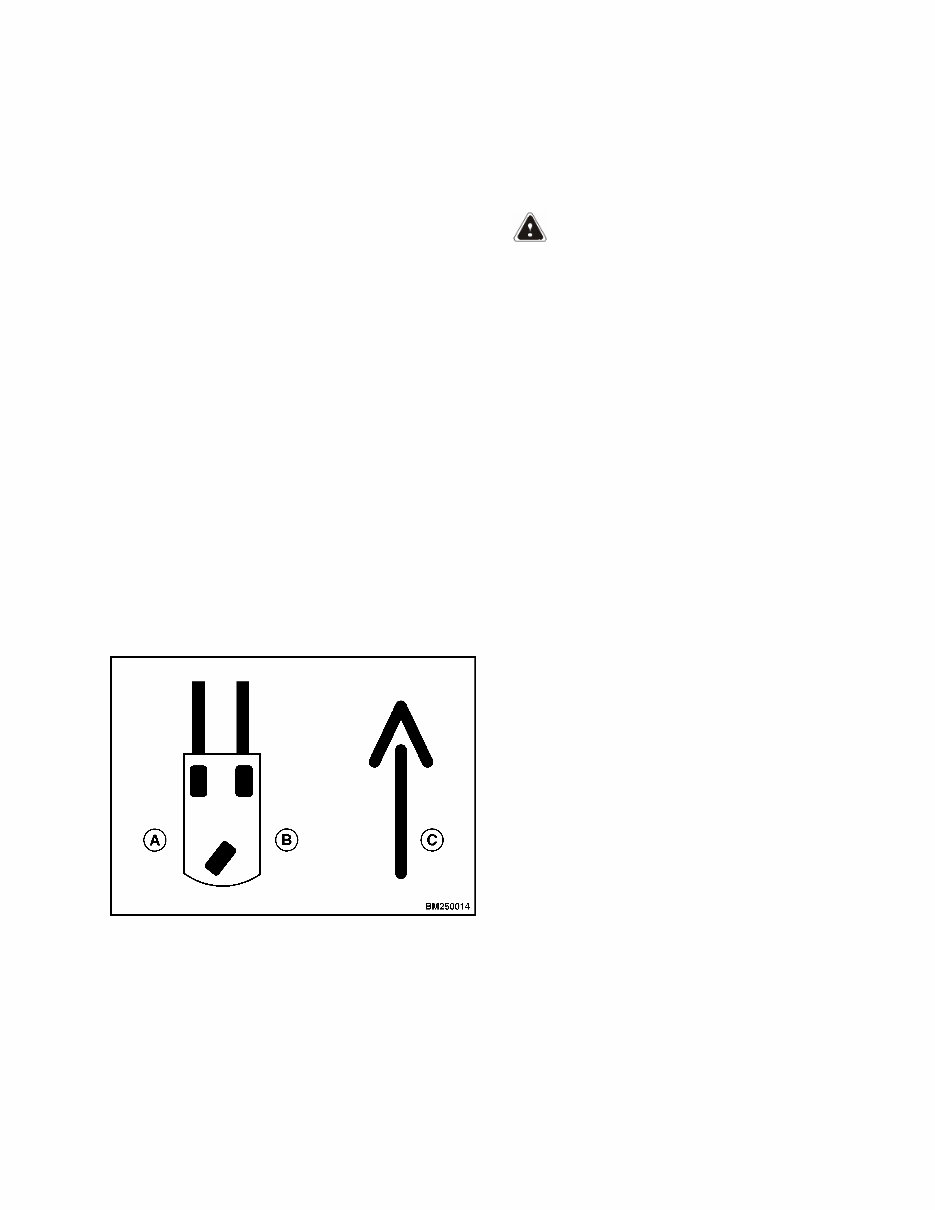
General INTRODUCTION This section contains the description and repair procedures for the steering system. Components covered are the steering wheel and column assembly, steering control unit, and steering actuator. Some parts associated with the steering system are not covered in this section because they are more closely associated with other systems. See the following for information not included in this section: See Electrical System 2200YRM1337 section for information on wiring and power supply for hydraulic pump and motor assembly. See Hydraulic System 1900YRM1333 section for information on hydraulic tank and system. See Periodic Maintenance 8000YRM1339 manual for information on regular schedule maintenance. Throughout this section, forward will refer to travel in the direction of the forks and left and right determined by an operator sitting in the seat facing forward. See Figure 1. A. LEFT SIDE B. RIGHT SIDE C. FORWARD TRAVEL Figure 1. Truck Orientation DISCHARGING THE CAPACITORS WARNING DO NOT make repairs or adjustments unless you have been properly trained and authorized to do so. Improper repairs and adjustments can create dangerous operating conditions. DO NOT operate a lift truck that needs repairs. Report the need for repairs to your supervisor immediately. If repair is necessary, attach a DO NOT OPERATE tag on the steering wheel and disconnect the battery. Disconnect the battery and allow the capacitors to discharge before opening an compartment covers or inspecting or repairing the electrical system. DO NOT place tool on top of the battery. If a tool causes a short circuit, the high current flow from the battery can cause personal injury and property damage. Some checks and adjustments are performed with the battery connected. DO NOT connect the battery until the procedure instructs you to do so. Never wear any metallic items on your fingers, arms, or neck. Metal items can accidentally make an electrical connection and cause injury Before performing any tests or adjustment, block the lift truck to prevent unexpected movement. The capacitor in the transistor controller(s) can hold an electrical charge for about 10 seconds after the battery is disconnected. To prevent an electrical shock and personal injury, discharge the capacitor(s) before inspecting or repairing any component in the drive unit compartment. Make certain that the battery has been disconnected. DO NOT short across the motor controller terminals with a screwdriver or jumper wire. Make certain the Emergency-Stop switch has not been activated. This will isolate the controller and prevent the capacitors from discharging properly. The proper way to disconnect the battery is by separating the battery connectors. 1600 YRM 1331 General 1
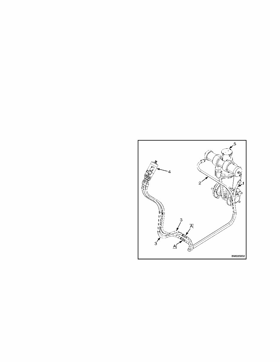
1. Ensure the capacitors are discharged by performing Step 2 through Step 6 below. 2. Turn key or keyless switch to OFF position. 3. Disconnect the battery by separating the connectors. 4. Block drive wheels to prevent lift truck from moving. 5. Make sure the Emergency-Stop switch HAS NOT been activated. If the Emergency-Stop switch is activated, rotate the switch to the right until it pops up. 6. Wait at least 30 seconds to be sure that the capacitors are fully discharged. Steering Pressure Check, Lift Trucks Equipped With Hydraulic Steering NOTE: The information in this section does not apply to lift truck models ERP15-20VT (G807) manufac- tured after November, 2014; these lift trucks are equipped with E-Steering (Electronic Steering) and do not use hydraulic fluid to control the steering axle. The steering system can be evaluated by checking the system pressure. Using a hydraulic pressure gauge, tee into the steering lines and check pressure between the steering control unit (on steering column) and steering actuator (steer axle). See Figure 2. 1. Remove floor mats and floor plates. 2. Turn key switch to the OFF position and discon- nect the battery connector. NOTE: Perform Step 3 through Step 14 for both right and left steer lines. 3. Insert a tee fitting at point A as shown in Figure 2, with gauge between steer line and hose assem- bly. 4. Connect battery connector and turn key switch to the ON position. 5. Ensure hydraulic oil in steer cylinder is between 49 to 60°C (120 to 140°F). NOTE: Step 6 through Step 8 apply to lift truck mod- els ERP030-040VT (G807) manufactured before No- vember, 2014 6. Turn steering wheel to full left or full right position to activate steering control unit and check pres- sure. Maximum pressure to be 7.5 ±0.25 MPa (1100 ± 36 psi). 7. If pressure is above 7.75 MPa (1136 psi) replace steering control unit. See Steering Control Unit (SCU) Repair, Lift Trucks Equipped With Hy- draulic Steering section. A. INSERT TEE FITTING WITH GAUGE 1. LEFT STEER LINE 2. RIGHT STEER LINE 3. HOSE ASSEMBLY 4. STEERING CONTROL UNIT 5. STEER AXLE Figure 2. Steering Pressure Check Steering Pressure Check, Lift Trucks Equipped With Hydraulic Steering 1600 YRM 1331 2
8. If pressure is below 7.25 bar (1064 psi) check the supply pressure from hydraulic pump: a. Turn key switch to OFF position and dis- connect battery connector. b. Install a gate valve (open) between steer line and tee fitting. c. Connect battery connector and turn key switch to ON position. d. Turn steering wheel to full left or full right position to activate steering control unit. e. SLOWLY close the gate valve to restrict flow of hy- draulic oil until gauge rises to 7.25 MPa (1064 psi), while steering wheel is in full left or full right position. f. If system pressure does not rise above 7.25 MPa (1064 psi), the hydraulic pump is not performing properly. Repair or replace hydraulic pump and motor assembly. See Hydraulic System 1900YRM1333. NOTE: Step 9 through Step 11 apply to lift truck models ERP030-040VT (G807) manufactured after November, 2014 9. Turn steering wheel to full left or full right position to activate steering control unit and check pres- sure. Maximum pressure to be 11.5 MPa (1667 psi). 10. If pressure is above 11.5 MPa (1667 psi) replace steering control unit. See Steering Control Unit (SCU) Repair, Lift Trucks Equipped With Hy- draulic Steering section. 11. If pressure is below 11.0 bar (1595 psi) check the supply pressure from hydraulic pump: a. Turn key switch to OFF position and dis- connect battery connector. b. Install a gate valve (open) between steer line and tee fitting. c. Connect battery connector and turn key switch to ON position. d. Turn steering wheel to full left or full right position to activate steering control unit. e. SLOWLY close the gate valve to restrict flow of hy- draulic oil until gauge rises to 11.0 MPa (1595 psi), while steering wheel is in full left or full right position. f. If system pressure does not rise above 11.0 MPa (1595 psi), the hydraulic pump is not performing properly. Repair or replace hydraulic pump and motor assembly. See Hydraulic System 1900YRM1333. 12. When pressure checks are complete, turn key switch to OFF position and disconnect the battery connector. 13. Remove tee fitting between steer line and hose assembly. 14. Reconnect steer line and hose assembly. 15. Reconnect the battery connector. 16. Install floor plates and floor mats. 17. Perform Operation Check. Operation Check The purpose of this check is to make sure steering trunnion turns the correct degrees of its rotation (ap- proximately 180 degrees). Put the lift truck on blocks so the weight of the lift truck is removed from the steering trunnion. See How to Put Lift Truck on Blocks in either Operating Manual or Periodic Maintenance 8000YRM1339. To operate steering system, rotate trunnion to its stop in one direction, then rotate trunnion to its stop in the other direction. Check that steering wheel turns trunnion smoothly. The face of the wheel should be approximately paral- lel to the frame plate at the back of the battery com- partment when the steering trunnion is rotated fully in each direction to its stops. Perform required repairs if steering system is not working correctly. 1600 YRM 1331 Operation Check 3
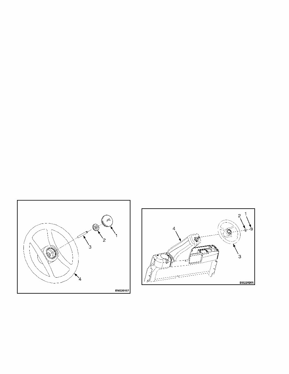
Steering Control Unit (SCU) Repair, Lift Trucks Equipped With Hydraulic Steering The information in this section does not apply to lift truck models ERP15-20VT (G807) manufactured after November, 2014; these lift trucks are equipped with E-Steering (Electronic Steering) and do not use hy- draulic fluid to control the steering axle. REMOVE NOTE: The following procedure to be used for fixed and telescopic steering columns. 1. Disconnect battery connector. 2. Discharge capacitors, for procedures see General section of this manual. NOTE: Tag all electrical connectors during removal to aid in installation. 3. Remove horn button, nut, and rod from steering wheel. See Figure 3. 4. Remove hex nut, washer (if equipped) and steer- ing wheel from steering column. If necessary, use puller tool to remove steering wheel. See Fig- ure 4. 1. HORN BUTTON 2. NUT 3. ROD 4. STEERING WHEEL Figure 3. Horn Button Assembly and Electrical Connections NOTE: Follow Step 5 through Step 9 for a fixed steering column. 5. Remove steering column upper cover by pressing from both sides and pulling up. Clips should re- main attached. See Figure 5. 6. Remove four capscrews and steering column lower cover. See Figure 5. 7. Remove four capscrews and steering column top cover. See Figure 5. NOTE: Tag wires prior to removal to aid in installa- tion. 8. Disconnect the horn wires from the horn switch. 9. Remove capscrews from dash panel and cowl plate. Lift dash panel over fixed steering column, maneuvering it past tilt adjust lever. NOTE: Follow Step 10 through Step 15 for a tele- scopic steering column. 10. Remove steering column top cover by pressing from both sides and pulling up. Clips should re- main attached. See Figure 6. 1. HEX NUT 2. WASHER 3. STEERING WHEEL 4. STEERING COLUMN Figure 4. Steering Wheel Steering Control Unit (SCU) Repair, Lift Trucks Equipped With Hydraulic Steering 1600 YRM 1331 4
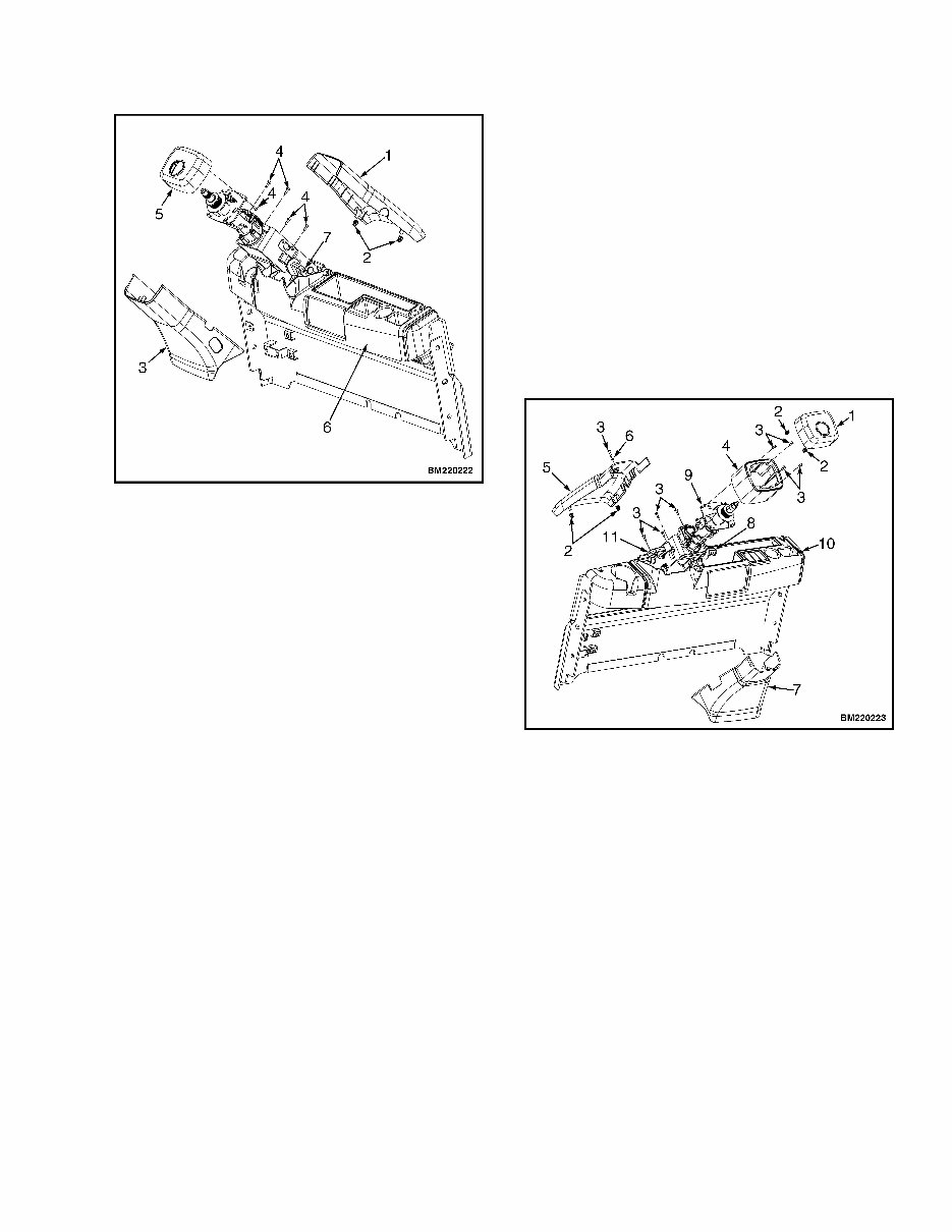
1. STEERING COLUMN UPPER COVER 2. CLIP 3. STEERING COLUMN LOWER COVER 4. CAPSCREW 5. STEERING COLUMN TOP COVER 6. DASH PANEL 7. TILT ADJUST LEVER Figure 5. Fixed Steering Column Covers 11. Remove four capscrews and steering column tel- escoping cover. See Figure 6. 12. Remove capscrew and washer; press steering column upper cover from both sides and pull up. Clips should remain attached. See Figure 6. 13. Remove four capscrews and steering column lower cover. Maneuver steering column lower cover around tilt memory lever. See Figure 6. NOTE: Tag wires prior to removal to aid in installa- tion. 14. Disconnect the horn wires from the horn switch. 15. Remove capscrews from dash panel and cowl plate. Lift dash panel over telescopic steering col- umn, maneuvering it past tilt memory lever, adjust lever, and column locking knob. NOTE: Tag all hoses and fittings during removal to aid in installation. NOTE: Install plugs at all hose ports and hose ends to prevent foreign material from entering hydraulic system. 16. Disconnect the hydraulic hoses from the steering control unit fittings. See Figure 7. Set the hy- draulic hoses aside to prevent possible damage. 1. STEERING COLUMN TOP COVER 2. CLIP 3. CAPSCREW 4. STEERING COLUMN TELESCOPING COVER 5. STEERING COLUMN UPPER COVER 6. WASHER 7. STEERING COLUMN LOWER COVER 8. TILT ADJUST LEVER 9. TELESCOPIC STEERING COLUMN 10. DASH PANEL 11. TILT MEMORY LEVER Figure 6. Telescopic Steering Column Covers 1600 YRM 1331 Steering Control Unit (SCU) Repair, Lift Trucks Equipped With Hydraulic Steering 5
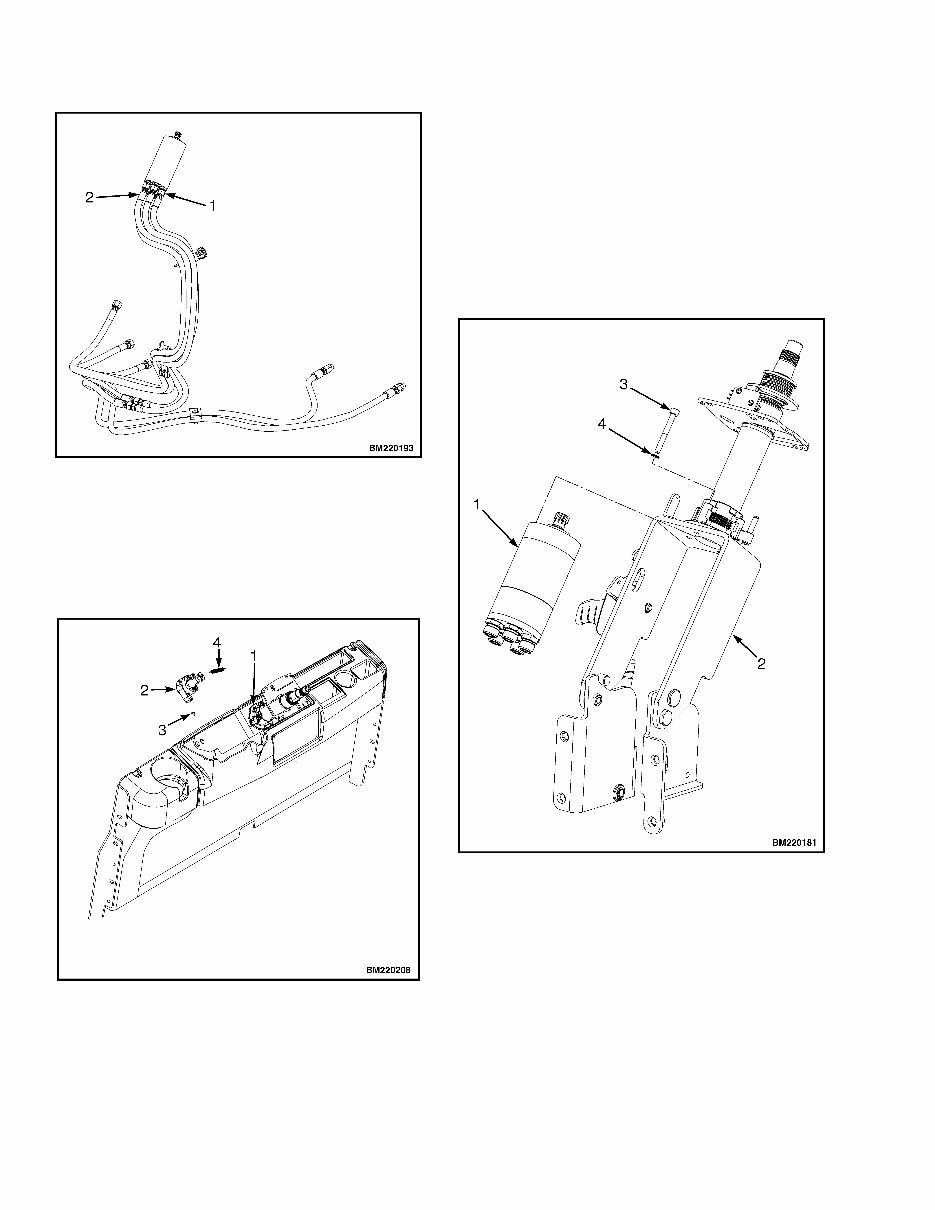
1. STEERING CONTROL UNIT FITTING 2. HYDRAULIC HOSE Figure 7. Hydraulic Hose Connections 17. Remove spring, e-ring, and steering direction sen- sor from steering column. See Figure 8. 1. STEERING COLUMN 2. STEERING DIRECTION SENSOR 3. E-RING 4. SPRING Figure 8. Steering Direction Sensor NOTE: Perform Step 18 for lift trucks equipped with synchronous steering. 18. Disconnect wiring harness from synchronous steering valve kit. See Figure 10. NOTE: Note placement and orientation of steering control unit prior to removal to aid in installation. 19. Remove capscrews, washers, and steering con- trol unit from tilt base bracket. See Figure 9. 1. STEERING CONTROL UNIT 2. TILT BASE BRACKET 3. CAPSCREW 4. WASHER Figure 9. Steering Control Unit Steering Control Unit (SCU) Repair, Lift Trucks Equipped With Hydraulic Steering 1600 YRM 1331 6
Are you facing issues with YALE G807 ERP030VT, ERP035VT, ERP040VT LIFT TRUCK maintenance? Do you need a reliable service repair manual for your YALE G807 ERP030VT, ERP035VT, ERP040VT LIFT TRUCK? Look no further! We have an electronic service repair manual that is rich in maintenance knowledge, making it a practical and convenient resource for both professional mechanics and DIY enthusiasts. This comprehensive manual covers various aspects including frame, operator's cab, AC motor repair, transaxle, steering system, brake system, hydraulic system, hydraulic cleanliness procedures, main control valves, cylinder repair, wire harness repair, user interface supervisor, user interface service technician, electrical system, industrial battery, mast repair, fasteners, periodic maintenance, capacities and specifications, diagrams, and diagnostic troubleshooting.
File Format: .PDF
Compatible: All Versions of Windows & Mac
Language: English
Requirements: Adobe Reader & Win
Having this manual at your disposal will ensure that your YALE G807 ERP030VT, ERP035VT, ERP040VT LIFT TRUCK receives the best service. The practical aspect of this electronic manual lies in its detailed explanations, accompanied by numerous pictures, words, and images, making it a comprehensive guide for repair. Its electronic format makes it practical, easy to carry, and readily accessible for on-site repairs. In today's digital age, electronic products have become an integral part of our lives. Embrace this trend with the electronic service repair manual, which not only meets the modern-day requirements but also adds a touch of fashion and sophistication to your maintenance endeavors. Whether you operate a repair shop or prefer DIY maintenance, the YALE G807 ERP030VT, ERP035VT, ERP040VT LIFT TRUCK service repair manual is your ultimate solution for tackling maintenance challenges.
Recently Viewed
5,521,897Happy Clients
2,594,462eManuals
1,120,453Trusted Sellers
15Years in Business
Price:
Actual Price:
YALE G807 ERP030VT, ERP035VT, ERP040VT Lift Truck Service Repair Manual