


Yale
IndustrialTrucks
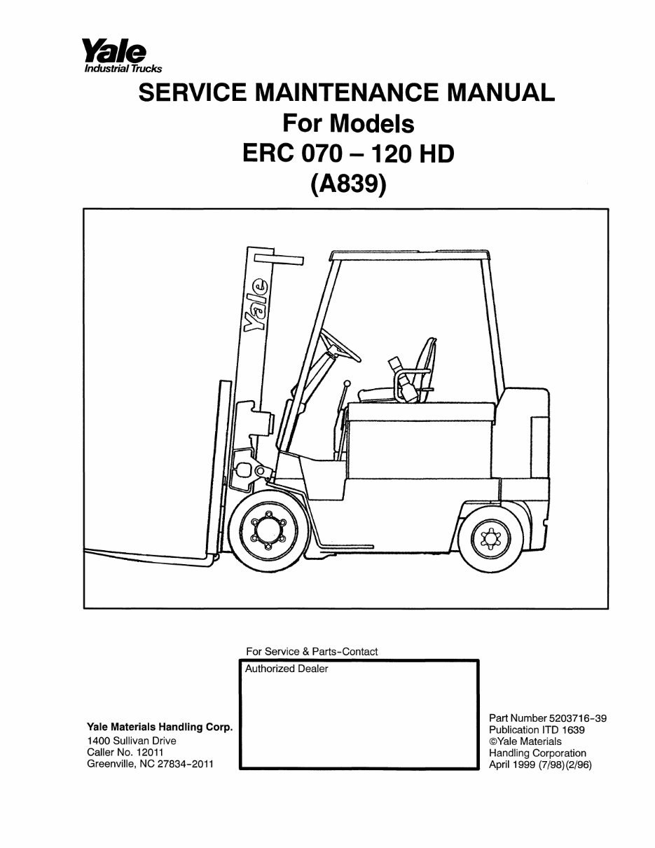
SERVICE MAINTENANCE MANUAL
For Models
ERC 070-120 HD
(A839)
S)
©
For Service & Parts-Contact
Yale Materials Handling Corp.
1400 Sullivan Drive
Caller No. 12011
Greenville, NC 27834-2011
Authorized Dea er
Part Number 5203716-39
Publication ITD 1639
©Yale Materials
Handling Corporation
April 1999 (7/98) (2/96)
Yale
IndustrialTrucks
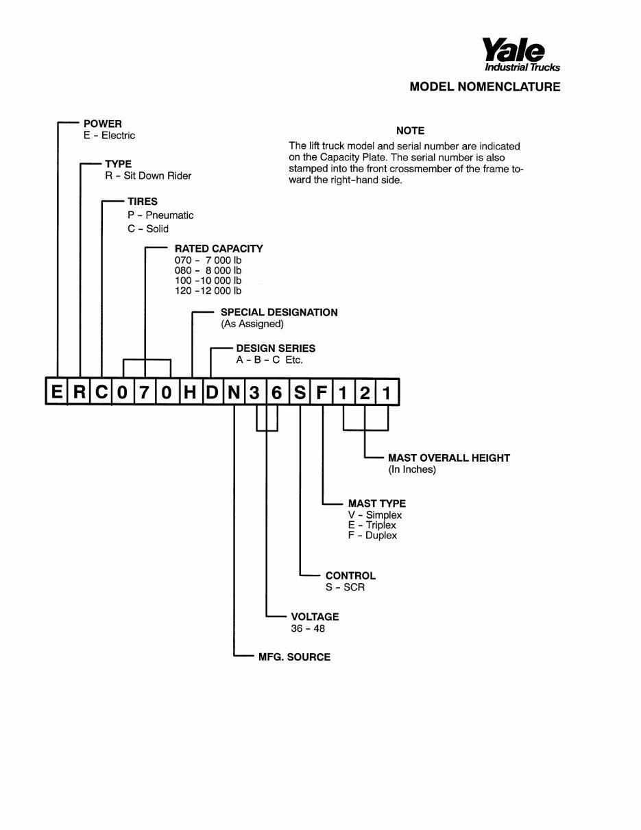
MODEL NOMENCLATURE
POWER
E - Electric
TYPE
R - Sit Down Rider
—
TIRES
P - Pneumatic
C - Solid
NOTE
The lift truck model and serial number are indicated
on the Capacity Plate. The serial number is also
stamped into the front crossmember of the frame to¬
ward the right-hand side.
RATED CAPACITY
070- 7 0001b
080- 8 0001b
100 -10 000 lb
120 -12 000 lb
H
SPECIAL DESIGNATION
(As Assigned)
-
DESIGN SERIES
A - B - C Etc.
D N 1 1
MAST OVERALL HEIGHT
(In Inches)
MAST TYPE
V - Simplex
E - Triplex
F - Duplex
CONTROL
S - SCR
VOLTAGE
36 - 48
MFG. SOURCE
Yale
Industrial Trucks
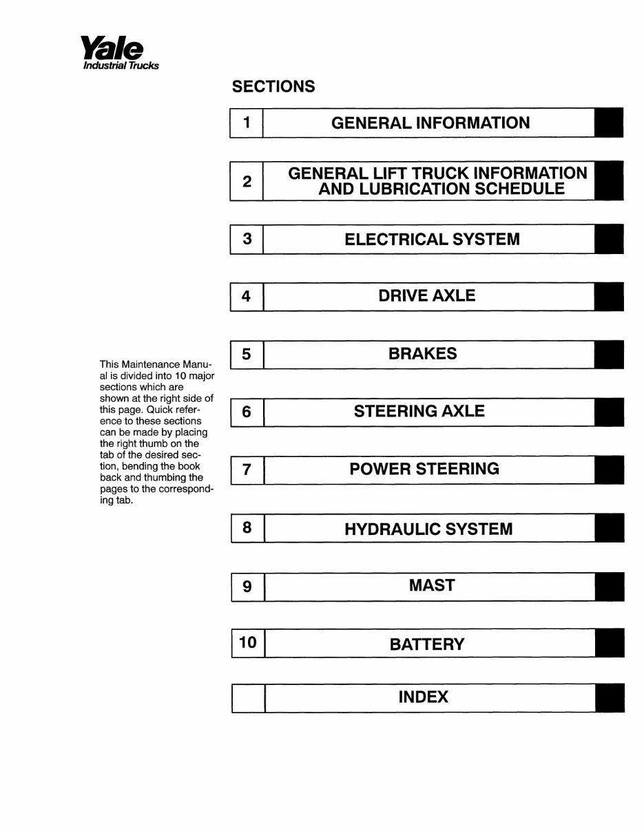
SECTIONS
GENERAL INFORMATION
GENERAL LIFT TRUCK INFORMATION
AND LUBRICATION SCHEDULE
ELECTRICAL SYSTEM
DRIVE AXLE
This Maintenance Manu¬
5 BRAKES
al is divided into 10 major
sections which are
shown at the right side of
this page. Quick refer¬
ence to these sections
6 STEERING AXLE
can be made by placing
the right thumb on the
tab of the desired sec¬
tion, bending the book
back and thumbing the
7 POWER STEERING
pages to the correspond¬
ing tab.
8
HYDRAULIC SYSTEM
MAST
10
BATTERY
INDEX
Yale
Industrial Trucks
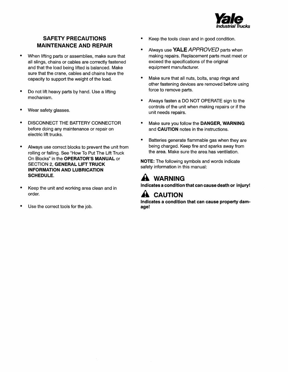
SAFETY PRECAUTIONS
MAINTENANCE AND REPAIR
• When lifting parts or assemblies, make sure that
ail slings, chains or cables are correctly fastened
and that the load being lifted is balanced. Make
sure that the crane, cables and chains have the
capacity to support the weight of the load.
• Do not lift heavy parts by hand. Use a lifting
mechanism.
• Wear safety glasses.
• DISCONNECT THE BATTERY CONNECTOR
before doing any maintenance or repair on
electric lift trucks.
• Always use correct blocks to prevent the unit from
rolling or falling. See "How To Put The Lift Truck
On Blocks" in the OPERATOR'S MANUAL or
SECTION 2, GENERAL LIFT TRUCK
INFORMATION AND LUBRICATION
SCHEDULE.
• Keep the unit and working area clean and in
order.
• Use the correct tools for the job.
• Keep the tools clean and in good condition.
• Always use YALE APPROVED parts when
making repairs. Replacement parts must meet or
exceed the specifications of the original
equipment manufacturer.
• Make sure that all nuts, bolts, snap rings and
other fastening devices are removed before using
force to remove parts.
• Always fasten a DO NOT OPERATE sign to the
controls of the unit when making repairs or if the
unit needs repairs.
• Make sure you follow the DANGER, WARNING
and CAUTION notes in the instructions.
• Batteries generate flammable gas when they are
being charged. Keep fire and sparks away from
the area. Make sure the area has ventilation.
NOTE: The following symbols and words indicate
safety information in this manual:
A WARNING
Indicates a condition that can cause death or injury!
A CAUTION
Indicates a condition that can cause property dam¬
age!
Yale
Industrial Trucks
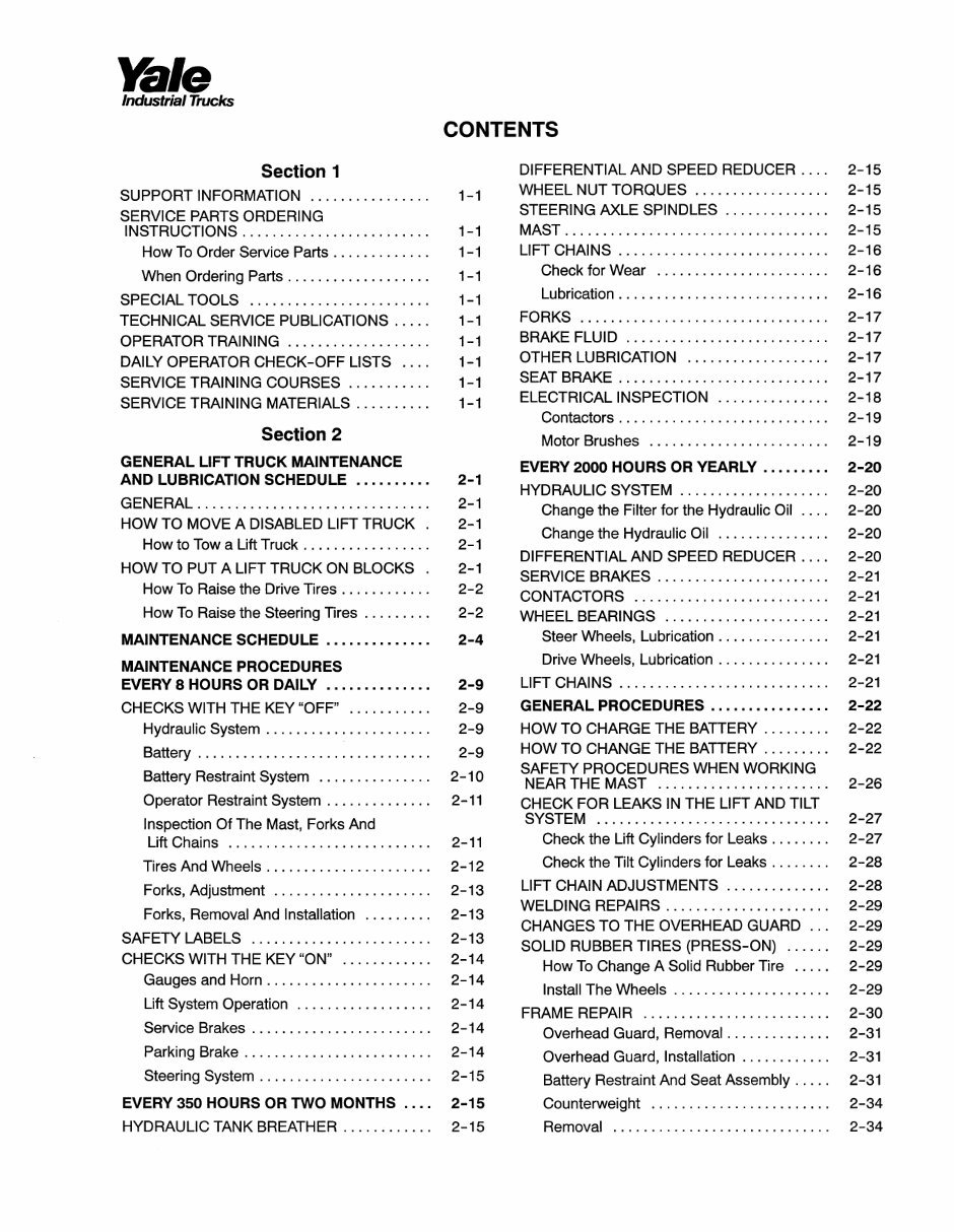
CONTENTS
Section 1
SUPPORT INFORMATION 1-1
SERVICE PARTS ORDERING
INSTRUCTIONS 1-1
How To Order Service Parts 1-1
When Ordering Parts 1-1
SPECIAL TOOLS 1-1
TECHNICAL SERVICE PUBLICATIONS ..... 1-1
OPERATOR TRAINING 1-1
DAILY OPERATOR CHECK-OFF LISTS .... 1-1
SERVICE TRAINING COURSES 1-1
SERVICE TRAINING MATERIALS 1-1
Section 2
GENERAL LIFT TRUCK MAINTENANCE
AND LUBRICATION SCHEDULE 2-1
GENERAL 2-1
HOW TO MOVE A DISABLED LIFT TRUCK . 2-1
How to Tow a Lift Truck 2-1
HOW TO PUT A LIFT TRUCK ON BLOCKS . 2-1
How To Raise the Drive Tires 2-2
How To Raise the Steering Tires 2-2
MAINTENANCE SCHEDULE 2-4
MAINTENANCE PROCEDURES
EVERY 8 HOURS OR DAILY 2-9
CHECKS WITH THE KEY "OFF" 2-9
Hydraulic System 2-9
Battery 2-9
Battery Restraint System 2-10
Operator Restraint System 2-11
Inspection Of The Mast, Forks And
Lift Chains 2-11
Tires And Wheels 2-12
Forks, Adjustment 2-13
Forks, Removal And Installation 2-13
SAFETY LABELS 2-13
CHECKS WITH THE KEY "ON" 2-14
Gauges and Horn 2-14
Lift System Operation 2-14
Service Brakes 2-14
Parking Brake 2-14
Steering System 2-15
EVERY 350 HOURS OR TWO MONTHS .... 2-15
HYDRAULIC TANK BREATHER 2-15
DIFFERENTIAL AND SPEED REDUCER .... 2-15
WHEEL NUT TORQUES 2-15
STEERING AXLE SPINDLES 2-15
MAST 2-15
LIFT CHAINS 2-16
Check for Wear 2-16
Lubrication 2-16
FORKS 2-17
BRAKE FLUID 2-17
OTHER LUBRICATION 2-17
SEAT BRAKE 2-17
ELECTRICAL INSPECTION 2-18
Contactors 2-19
Motor Brushes 2-19
EVERY 2000 HOURS OR YEARLY 2-20
HYDRAULIC SYSTEM 2-20
Change the Filter for the Hydraulic Oil
____
2-20
Change the Hydraulic Oil 2-20
DIFFERENTIAL AND SPEED REDUCER .... 2-20
SERVICE BRAKES 2-21
CONTACTORS 2-21
WHEEL BEARINGS 2-21
Steer Wheels, Lubrication 2-21
Drive Wheels, Lubrication 2-21
LIFT CHAINS 2-21
GENERAL PROCEDURES 2-22
HOW TO CHARGE THE BATTERY 2-22
HOW TO CHANGE THE BATTERY 2-22
SAFETY PROCEDURES WHEN WORKING
NEAR THE MAST 2-26
CHECK FOR LEAKS IN THE LIFT AND TILT
SYSTEM 2-27
Check the Lift Cylinders for Leaks 2-27
Check the Tilt Cylinders for Leaks 2-28
LIFT CHAIN ADJUSTMENTS 2-28
WELDING REPAIRS 2-29
CHANGES TO THE OVERHEAD GUARD ... 2-29
SOLID RUBBER TIRES (PRESS-ON) ...... 2-29
How To Change A Solid Rubber Tire ..... 2-29
Install The Wheels 2-29
FRAME REPAIR 2-30
Overhead Guard, Removal 2-31
Overhead Guard, Installation 2-31
Battery Restraint And Seat Assembly ..... 2-31
Counterweight 2-34
Removal 2-34
Yale
Industrial Trucks
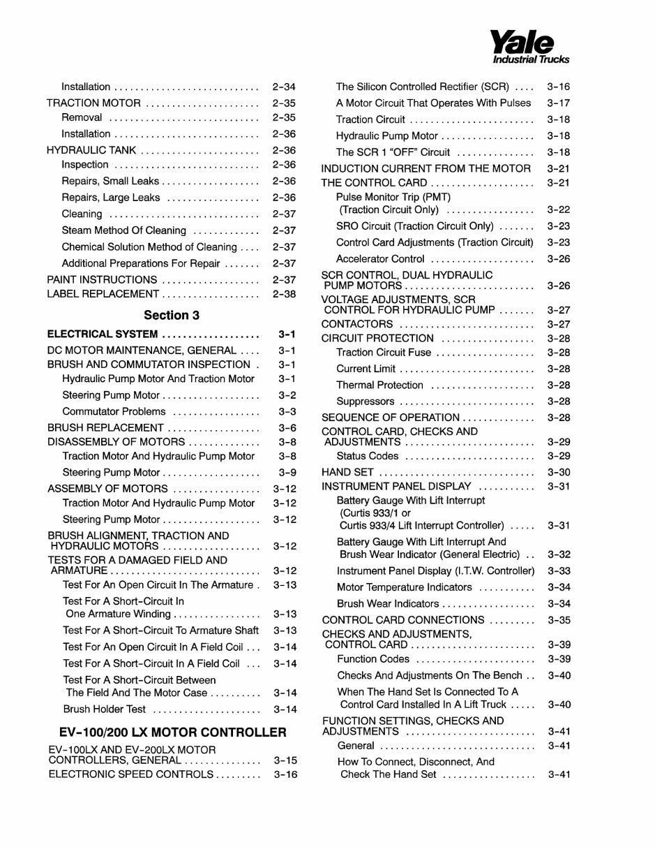
Installation 2-34
TRACTION MOTOR 2-35
Removal 2-35
Installation 2-36
HYDRAULIC TANK 2-36
Inspection 2-36
Repairs, Small Leaks 2-36
Repairs, Large Leaks 2-36
Cleaning 2-37
Steam Method Of Cleaning 2-37
Chemical Solution Method of Cleaning
____
2-37
Additional Preparations For Repair 2-37
PAINT INSTRUCTIONS 2-37
LABEL REPLACEMENT 2-38
Section 3
ELECTRICAL SYSTEM 3-1
DC MOTOR MAINTENANCE, GENERAI
_____
3-1
BRUSH AND COMMUTATOR INSPECTION . 3-1
Hydraulic Pump Motor And Traction Motor 3-1
Steering Pump Motor 3-2
Commutator Problems 3-3
BRUSH REPLACEMENT 3-6
DISASSEMBLY OF MOTORS 3-8
Traction Motor And Hydraulic Pump Motor 3-8
Steering Pump Motor 3-9
ASSEMBLY OF MOTORS 3-12
Traction Motor And Hydraulic Pump Motor 3-12
Steering Pump Motor 3-12
BRUSH ALIGNMENT, TRACTION AND
HYDRAULIC MOTORS 3-12
TESTS FOR A DAMAGED FIELD AND
ARMATURE 3-12
Test For An Open Circuit In The Armature . 3-13
Test For A Short-Circuit In
One Armature Winding 3-13
Test For A Short-Circuit To Armature Shaft 3-13
Test For An Open Circuit In A Field Coil ... 3-14
Test For A Short-Circuit In A Field Coil ... 3-14
Test For A Short-Circuit Between
The Field And The Motor Case 3-14
Brush Holder Test 3-14
EV-1
00/200
LX MOTOR CONTROLLER
EV-100LX AND EV-200LX MOTOR
CONTROLLERS, GENERAL 3-15
ELECTRONIC SPEED CONTROLS 3-16
The Silicon Controlled Rectifier (SCR) .... 3-16
A Motor Circuit That Operates With Pulses 3-17
Traction Circuit 3-18
Hydraulic Pump Motor 3-18
The SCR 1 "OFF" Circuit 3-18
INDUCTION CURRENT FROM THE MOTOR 3-21
THE CONTROL CARD 3-21
Pulse Monitor Trip (PMT)
(Traction Circuit Only) 3-22
SRO Circuit (Traction Circuit Only) 3-23
Control Card Adjustments (Traction Circuit) 3-23
Accelerator Control 3-26
SCR CONTROL, DUAL HYDRAULIC
PUMP MOTORS 3-26
VOLTAGE ADJUSTMENTS, SCR
CONTROL FOR HYDRAULIC PUMP 3-27
CONTACTORS 3-27
CIRCUIT PROTECTION 3-28
Traction Circuit Fuse 3-28
Current Limit 3-28
Thermal Protection 3-28
Suppressors 3-28
SEQUENCE OF OPERATION 3-28
CONTROL CARD, CHECKS AND
ADJUSTMENTS 3-29
Status Codes 3-29
HAND SET 3-30
INSTRUMENT PANEL DISPLAY 3-31
Battery Gauge With Lift Interrupt
(Curtis 933/1 or
Curtis 933/4 Lift Interrupt Controller) ..... 3-31
Battery Gauge With Lift Interrupt And
Brush Wear Indicator (General Electric) .. 3-32
Instrument Panel Display (I.T.W. Controller) 3-33
Motor Temperature Indicators 3-34
Brush Wear Indicators 3-34
CONTROL CARD CONNECTIONS 3-35
CHECKS AND ADJUSTMENTS,
CONTROL CARD 3-39
Function Codes 3-39
Checks And Adjustments On The Bench . . 3-40
When The Hand Set Is Connected To A
Control Card Installed In A Lift Truck ..... 3-40
FUNCTION SETTINGS, CHECKS AND
ADJUSTMENTS 3-41
General 3-41
How To Connect, Disconnect, And
Check The Hand Set 3-41
Yale
Industrial Trucks
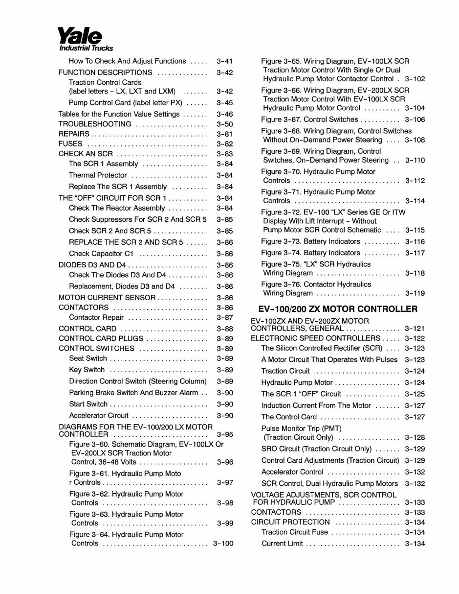
How To Check And Adjust Functions ..... 3-41
FUNCTION DESCRIPTIONS 3-42
Traction Control Cards
(label letters - LX, LXT and LXM) 3-42
Pump Control Card (label letter PX) ...... 3-45
Tables for the Function Value Settings 3-46
TROUBLESHOOTING 3-50
REPAIRS 3-81
FUSES 3-82
CHECK AN SCR 3-83
The SCR 1 Assembly 3-84
Thermal Protector 3-84
Replace The SCR 1 Assembly 3-84
THE "OFF" CIRCUIT FOR SCR 1 3-84
Check The Reactor Assembly 3-84
Check Suppressors For SCR 2 And SCR 5 3-85
Check SCR 2 And SCR 5 3-85
REPLACE THE SCR 2 AND SCR 5 ...... 3-86
Check Capacitor C1 3-86
DIODES D3 AND D4 3-86
Check The Diodes D3 And D4 3-86
Replacement, Diodes D3 and D4 3-86
MOTOR CURRENT SENSOR 3-86
CONTACTORS 3-86
Contactor Repair 3-87
CONTROL CARD 3-88
CONTROL CARD PLUGS 3-89
CONTROL SWITCHES 3-89
Seat Switch 3-89
Key Switch 3-89
Direction Control Switch (Steering Column) 3-89
Parking Brake Switch And Buzzer Alarm . . 3-90
Start Switch 3-90
Accelerator Circuit 3-90
DIAGRAMS FOR THE EV-1
00/200
LX MOTOR
CONTROLLER 3-95
Figure 3-60. Schematic Diagram, EV-100LX Or
EV-200LX SCR Traction Motor
Control, 36-48 Volts 3-96
Figure 3-61. Hydraulic Pump Moto
r Controls 3-97
Figure 3-62. Hydraulic Pump Motor
Controls 3-98
Figure 3-63. Hydraulic Pump Motor
Controls 3-99
Figure 3-64. Hydraulic Pump Motor
Controls 3-100
Figure 3-65. Wiring Diagram, EV-100LX SCR
Traction Motor Control With Single Or Dual
Hydraulic Pump Motor Contactor Control . 3-102
Figure 3-66. Wiring Diagram, EV-200LX SCR
Traction Motor Control With EV-100LX SCR
Hydraulic Pump Motor Control 3-104
Figure 3-67. Control Switches 3-106
Figure 3-68. Wiring Diagram, Control Switches
Without On-Demand Power Steering
____
3-108
Figure 3-69. Wiring Diagram, Control
Switches, On-Demand Power Steering .. 3-110
Figure 3-70. Hydraulic Pump Motor
Controls 3-112
Figure 3-71. Hydraulic Pump Motor
Controls 3-114
Figure 3-72. EV-1 00 "LX" Series GE Or ITW
Display With Lift Interrupt - Without
Pump Motor SCR Control Schematic .... 3-115
Figure 3-73. Battery Indicators 3-116
Figure 3-74. Battery Indicators 3-117
Figure 3-75. "LX" SCR Hydraulics
Wiring Diagram 3-118
Figure 3-76. Contactor Hydraulics
Wiring Diagram 3-119
EV-1
00/200
ZX MOTOR CONTROLLER
EV-100ZX AND EV-200ZX MOTOR
CONTROLLERS, GENERAL 3-121
ELECTRONIC SPEED CONTROLLERS ..... 3-122
The Silicon Controlled Rectifier (SCR) .... 3-123
A Motor Circuit That Operates With Pulses 3-123
Traction Circuit 3-124
Hydraulic Pump Motor 3-124
The SCR 1 "OFF" Circuit 3-125
Induction Current From The Motor ....... 3-127
The Control Card 3-127
Pulse Monitor Trip (PMT)
(Traction Circuit Only) 3-128
SRO Circuit (Traction Circuit Only) ....... 3-129
Control Card Adjustments (Traction Circuit) 3-129
Accelerator Control 3-132
SCR Control, Dual Hydraulic Pump Motors 3-132
VOLTAGE ADJUSTMENTS, SCR CONTROL
FOR HYDRAULIC PUMP 3-133
CONTACTORS 3-133
CIRCUIT PROTECTION 3-134
Traction Circuit Fuse 3-134
Current Limit 3-134
Yale
Industrial Trucks
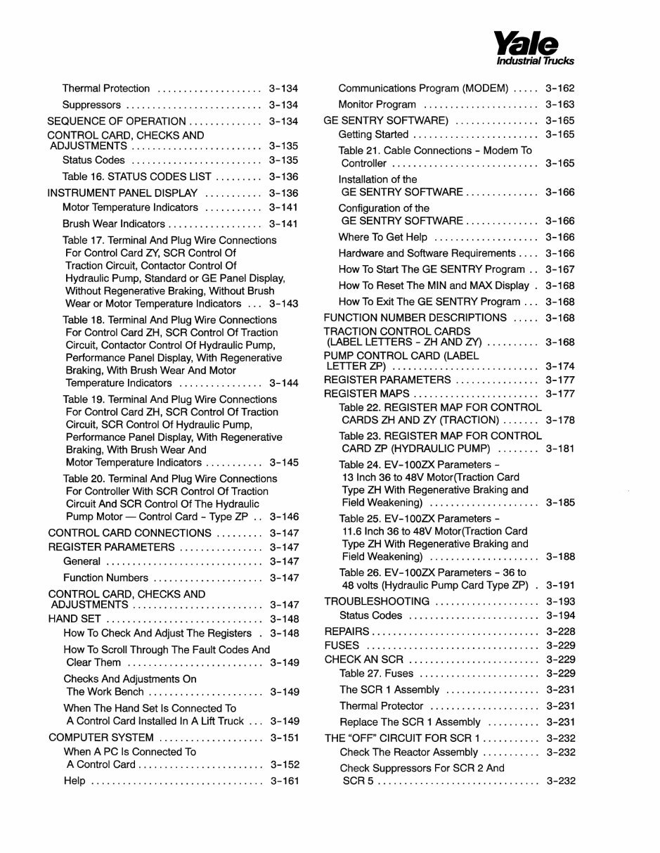
Thermal Protection 3-134
Suppressors 3-134
SEQUENCE OF OPERATION 3-134
CONTROL CARD, CHECKS AND
ADJUSTMENTS 3-135
Status Codes 3-135
Table 16. STATUS CODES LIST 3-136
INSTRUMENT PANEL DISPLAY 3-136
Motor Temperature Indicators 3-141
Brush Wear Indicators 3-141
Table 17. Terminal And Plug Wire Connections
For Control Card ZY, SCR Control Of
Traction Circuit, Contactor Control Of
Hydraulic Pump, Standard or GE Panel Display,
Without Regenerative Braking, Without Brush
Wear or Motor Temperature Indicators ... 3-143
Table 18. Terminal And Plug Wire Connections
For Control Card ZH, SCR Control Of Traction
Circuit, Contactor Control Of Hydraulic Pump,
Performance Panel Display, With Regenerative
Braking, With Brush Wear And Motor
Temperature Indicators 3-144
Table 19. Terminal And Plug Wire Connections
For Control Card ZH, SCR Control Of Traction
Circuit, SCR Control Of Hydraulic Pump,
Performance Panel Display, With Regenerative
Braking, With Brush Wear And
Motor Temperature Indicators 3-145
Table 20. Terminal And Plug Wire Connections
For Controller With SCR Control Of Traction
Circuit And SCR Control Of The Hydraulic
Pump Motor — Control Card - Type ZP .. 3-146
CONTROL CARD CONNECTIONS 3-147
REGISTER PARAMETERS 3-147
General 3-147
Function Numbers 3-147
CONTROL CARD, CHECKS AND
ADJUSTMENTS 3-147
HANDSET 3-148
How To Check And Adjust The Registers . 3-148
How To Scroll Through The Fault Codes And
Clear Them 3-149
Checks And Adjustments On
The Work Bench 3-149
When The Hand Set Is Connected To
A Control Card Installed In A Lift Truck . . . 3-149
COMPUTER SYSTEM 3-151
When A PC Is Connected To
A Control Card 3-152
Help 3-161
Communications Program (MODEM) ..... 3-162
Monitor Program 3-163
GE SENTRY SOFTWARE) 3-165
Getting Started 3-165
Table 21. Cable Connections - Modem To
Controller 3-165
Installation of the
GE SENTRY SOFTWARE 3-166
Configuration of the
GE SENTRY SOFTWARE 3-166
Where To Get Help 3-166
Hardware and Software Requirements
____
3-166
How To Start The GE SENTRY Program . . 3-167
How To Reset The MIN and MAX Display . 3-168
How To Exit The GE SENTRY Program ... 3-168
FUNCTION NUMBER DESCRIPTIONS ..... 3-168
TRACTION CONTROL CARDS
(LABEL LETTERS - ZH AND ZY) 3-168
PUMP CONTROL CARD (LABEL
LETTER ZP) 3-174
REGISTER PARAMETERS 3-177
REGISTER MAPS 3-177
Table 22. REGISTER MAP FOR CONTROL
CARDS ZH AND ZY (TRACTION) ....... 3-178
Table 23. REGISTER MAP FOR CONTROL
CARD ZP (HYDRAULIC PUMP) 3-181
Table 24. EV-100ZX Parameters -
13 Inch 36 to 48V Motor(Traction Card
Type ZH With Regenerative Braking and
Field Weakening) 3-185
Table 25. EV-100ZX Parameters -
11.6 Inch 36 to 48V Motor(Traction Card
Type ZH With Regenerative Braking and
Field Weakening) 3-188
Table 26. EV-100ZX Parameters - 36 to
48 volts (Hydraulic Pump Card Type ZP) . 3-191
TROUBLESHOOTING 3-193
Status Codes 3-194
REPAIRS 3-228
FUSES 3-229
CHECK AN SCR 3-229
Table 27. Fuses 3-229
The SCR 1 Assembly 3-231
Thermal Protector 3-231
Replace The SCR 1 Assembly 3-231
THE "OFF" CIRCUIT FOR SCR 1 3-232
Check The Reactor Assembly 3-232
Check Suppressors For SCR 2 And
SCR 5 3-232
Yale
Industrial Trucks
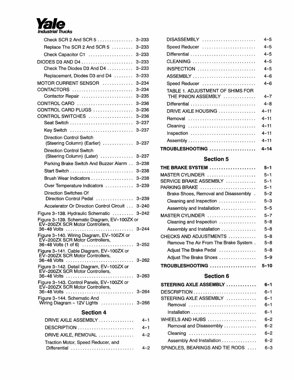
Check SCR 2 And SCR 5 3-233
Replace The SCR 2 And SCR 5 3-233
Check Capacitor C1 3-233
DIODES D3 AND D4 3-233
Check The Diodes D3 And D4 3-233
Replacement, Diodes D3 and D4 3-233
MOTOR CURRENT SENSOR 3-234
CONTACTORS 3-234
Contactor Repair 3-235
CONTROL CARD 3-236
CONTROL CARD PLUGS 3-236
CONTROL SWITCHES 3-236
Seat Switch 3-237
Key Switch 3-237
Direction Control Switch
(Steering Column) (Earlier) 3-237
Direction Control Switch
(Steering Column) (Later) 3-237
Parking Brake Switch And Buzzer Alarm . . 3-238
Start Switch 3-238
Brush Wear Indicators 3-238
Over Temperature Indicators 3-239
Direction Switches Of
Direction Control Pedal 3-239
Accelerator Or Direction Control Circuit . . . 3-240
Figure 3-138. Hydraulic Schematic 3-242
Figure 3-139. Schematic Diagram, EV-100ZX or
EV-200ZX SCR Motor Controllers,
36-48 Volts 3-244
Figure 3-140. Wiring Diagram, EV-100ZX or
EV-200ZX SCR Motor Controllers,
36-48 Volts (1 of 6) 3-252
Figure 3-141. Cable Diagram, EV-100ZX or
EV-200ZX SCR Motor Controllers,
36-48 Volts 3-262
Figure 3-142. Detail Diagram, EV-100ZX or
EV-200ZX SCR Motor Controllers,
36-48 Volts 3-263
Figure 3-143. Control Panels, EV-100ZXor
EV-200ZX SCR Motor Controllers,
36-48 Volts 3-264
Figure 3-144. Schematic And
Wiring Diagram - 12V Lights 3-266
Section 4
DRIVE AXLE ASSEMBLY 4-1
DESCRIPTION 4-1
DRIVE AXLE, REMOVAL 4-2
Traction Motor, Speed Reducer, and
Differential 4-2
DISASSEMBLY 4-5
Speed Reducer 4-5
Differential 4-5
CLEANING 4-5
INSPECTION 4-5
ASSEMBLY 4-6
Speed Reducer 4-6
TABLE 1. ADJUSTMENT OF SHIMS FOR
THE PINION ASSEMBLY 4-7
Differential 4-8
DRIVE AXLE HOUSING 4-11
Removal 4-11
Cleaning 4-11
Inspection 4-11
Assembly 4-11
TROUBLESHOOTING 4-14
Section 5
THE BRAKE SYSTEM 5-1
MASTER CYLINDER 5-1
SERVICE BRAKE ASSEMBLY 5-1
PARKING BRAKE 5-1
Brake Shoes, Removal and Disassembly . 5-2
Cleaning and Inspection 5-3
Assembly and Installation 5-5
MASTER CYLINDER 5-7
Cleaning and Inspection 5-8
Assembly and Installation 5-8
CHECKS AND ADJUSTMENTS 5-8
Remove The Air From The Brake System . 5-8
Adjust The Brake Pedal 5-8
Adjust The Brake Shoes 5-9
TROUBLESHOOTING 5-10
Section 6
STEERING AXLE ASSEMBLY 6-1
DESCRIPTION 6-1
STEERING AXLE ASSEMBLY 6-1
Removal 6-1
Installation 6-1
WHEELS AND HUBS 6-2
Removal and Disassembly 6-2
Cleaning 6-2
Assembly And Installation 6-2
SPINDLES, BEARINGS AND TIE RODS .... 6-3
Yale
Industrial Trucks
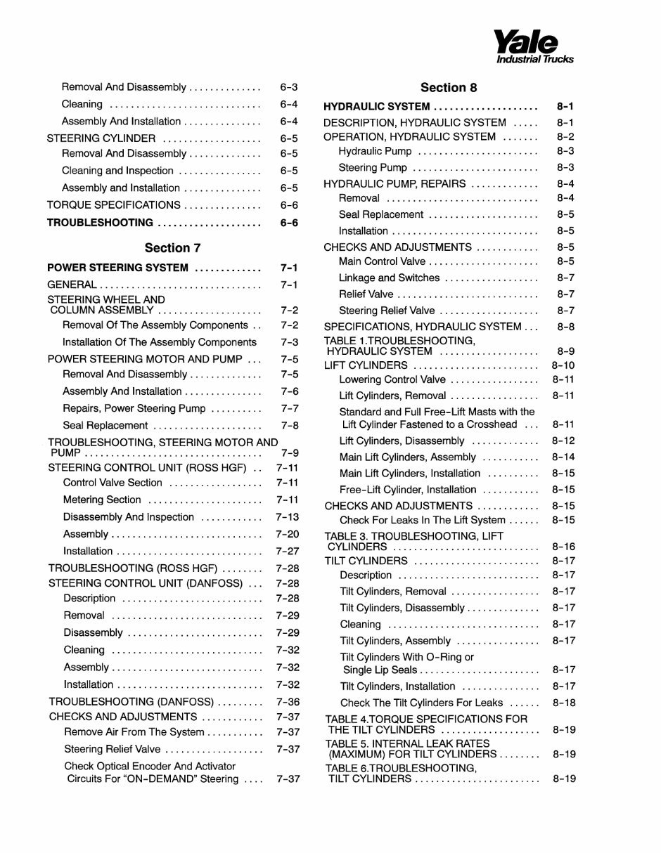
Removal And Disassembly 6-3
Cleaning 6-4
Assembly And Installation 6-4
STEERING CYLINDER 6-5
Removal And Disassembly 6-5
Cleaning and Inspection 6-5
Assembly and Installation 6-5
TORQUE SPECIFICATIONS 6-6
TROUBLESHOOTING 6-6
Section 7
POWER STEERING SYSTEM 7-1
GENERAL 7-1
STEERING WHEEL AND
COLUMN ASSEMBLY 7-2
Removal Of The Assembly Components . . 7-2
Installation Of The Assembly Components 7-3
POWER STEERING MOTOR AND PUMP ... 7-5
Removal And Disassembly 7-5
Assembly And Installation 7-6
Repairs, Power Steering Pump 7-7
Seal Replacement 7-8
TROUBLESHOOTING, STEERING MOTOR AND
PUMP 7-9
STEERING CONTROL UNIT (ROSS HGF) .. 7-11
Control Valve Section 7-11
Metering Section 7-11
Disassembly And Inspection 7-13
Assembly 7-20
Installation 7-27
TROUBLESHOOTING (ROSS HGF) 7-28
STEERING CONTROL UNIT (DANFOSS) ... 7-28
Description 7-28
Removal 7-29
Disassembly 7-29
Cleaning 7-32
Assembly 7-32
Installation 7-32
TROUBLESHOOTING (DANFOSS) 7-36
CHECKS AND ADJUSTMENTS 7-37
Remove Air From The System 7-37
Steering Relief Valve 7-37
Check Optical Encoder And Activator
Circuits For "ON-DEMAND" Steering .... 7-37
Section 8
HYDRAULIC SYSTEM 8-1
DESCRIPTION, HYDRAULIC SYSTEM ..... 8-1
OPERATION, HYDRAULIC SYSTEM 8-2
Hydraulic Pump 8-3
Steering Pump 8-3
HYDRAULIC PUMP, REPAIRS 8-4
Removal 8-4
Seal Replacement 8-5
Installation 8-5
CHECKS AND ADJUSTMENTS 8-5
Main Control Valve 8-5
Linkage and Switches 8-7
Relief Valve 8-7
Steering Relief Valve 8-7
SPECIFICATIONS, HYDRAULIC SYSTEM ... 8-8
TABLE 1. TROUBLESHOOTING,
HYDRAULIC SYSTEM 8-9
LIFT CYLINDERS 8-10
Lowering Control Valve 8-11
Lift Cylinders, Removal 8-11
Standard and Full Free-Lift Masts with the
Lift Cylinder Fastened to a Crosshead ... 8-11
Lift Cylinders, Disassembly 8-12
Main Lift Cylinders, Assembly 8-14
Main Lift Cylinders, Installation 8-15
Free-Lift Cylinder, Installation 8-15
CHECKS AND ADJUSTMENTS 8-15
Check For Leaks In The Lift System ...... 8-15
TABLE 3. TROUBLESHOOTING, LIFT
CYLINDERS 8-16
TILT CYLINDERS 8-17
Description 8-17
Tilt Cylinders, Removal 8-17
Tilt Cylinders, Disassembly 8-17
Cleaning 8-17
Tilt Cylinders, Assembly 8-17
Tilt Cylinders With O-Ring or
Single Lip Seals 8-17
Tilt Cylinders, Installation 8-17
Check The Tilt Cylinders For Leaks ...... 8-18
TABLE 4.TORQUE SPECIFICATIONS FOR
THE TILT CYLINDERS 8-19
TABLE 5. INTERNAL LEAK RATES
(MAXIMUM) FOR TILT CYLINDERS 8-19
TABLE 6.TROUBLESHOOTING,
TILT CYLINDERS 8-19
You're Reading a Preview
What's Included?
 Lifetime Access
Fast Download Speeds
Online & Offline Access
Access PDF Contents & Bookmarks
Full Search Facility
Print one or all pages of your manual
$35.99
$46.99
Yale Forklift Truck A839 Series: ERC070HD, ERC080HD, ERC100HD, ERC120HD Workshop Manual
Viewed 53 Times Today

What's Included?
Lifetime Access
Fast Download Speeds
Online & Offline Access
Access PDF Contents & Bookmarks
Full Search Facility
Print one or all pages of your manual
$35.99
$46.99

Secure transaction
What's Included?
Lifetime Access
Fast Download Speeds
Online & Offline Access
Access PDF Contents & Bookmarks
Full Search Facility
Print one or all pages of your manual
Original Illustrated Factory Workshop Manual for Yale Forklift Truck HD (A839) Series.
This original factory manual for Yale Forklift Trucks contains high-quality images, circuit diagrams, and instructions to help you operate and repair your truck. The manual is printable and contains searchable text.
Covered models:
- ERC070HD
- ERC080HD
- ERC100HD
- ERC120HD
Format: 507 Pages
Language: English
Contents:
- Section 1
- SUPPORT INFORMATION
- SERVICE PARTS ORDERING
- INSTRUCTIONS
- How To Order Service Parts
- When Ordering Parts
- SPECIAL TOOLS
- TECHNICAL SERVICE PUBLICATIONS
- OPERATOR TRAINING
- DAILY OPERATOR CHECK-OFF LISTS
- SERVICE TRAINING COURSES
- SERVICE TRAINING MATERIALS
- Section 2
- GENERAL LIFT TRUCK MAINTENANCE AND LUBRICATION SCHEDULE
- MAINTENANCE SCHEDULE
- MAINTENANCE PROCEDURES
- EVERY 8 HOURS OR DAILY
- CHECKS WITH THE KEY "OFF"
- CHECKS WITH THE KEY "ON"
- EVERY 350 HOURS OR TWO MONTHS
- EVERY 2000 HOURS OR YEARLY
- GENERAL PROCEDURES
- SAFETY PROCEDURES WHEN WORKING NEAR THE MAST
- WELDING REPAIRS
- FRAME REPAIR
- Section 3
- ELECTRICAL SYSTEM
- DC MOTOR MAINTENANCE, GENERAL
- BRUSH AND COMMUTATOR INSPECTION
- BRUSH REPLACEMENT
- DISASSEMBLY OF MOTORS
- ASSEMBLY OF MOTORS
- TESTS FOR A DAMAGED FIELD AND ARMATURE
- EV-100/200 LX MOTOR CONTROLLER
- EV-100LX AND EV-200LX MOTOR CONTROLLERS, GENERAL
- ELECTRONIC SPEED CONTROLS
- SCR CONTROL, DUAL HYDRAULIC PUMP MOTORS
- CONTACTORS
- CIRCUIT PROTECTION
- SEQUENCE OF OPERATION
- INSTRUMENT PANEL DISPLAY
- CONTROL CARD CONNECTIONS
- FUNCTION SETTINGS, CHECKS AND ADJUSTMENTS
- FUNCTION DESCRIPTIONS
- TROUBLESHOOTING
- REPAIRS
- Section 8
- HYDRAULIC SYSTEM
- DESCRIPTION, HYDRAULIC SYSTEM
- OPERATION, HYDRAULIC SYSTEM
- HYDRAULIC PUMP, REPAIRS
- CHECKS AND ADJUSTMENTS
- SPECIFICATIONS, HYDRAULIC SYSTEM
- LIFT CYLINDERS
- TILT CYLINDERS
- MAIN CONTROL VALVE
- SOLENOID VALVE FOR AUXILIARY FUNCTION
- REPAIRS
- CHECKS AND ADJUSTMENTS
- CONTROL LEVER ARRANGEMENT
- TROUBLESHOOTING, HYDRAULIC SYSTEM
- Section 9
- MAST
- DESCRIPTION AND OPERATION
- REPAIRS
- CHECKS AND ADJUSTMENTS
- TROUBLESHOOTING, MAST
- Section 10
- THE INDUSTRIAL BATTERY
- GENERAL
- LEAD-ACID BATTERIES
- BATTERY MAINTENANCE
- CHARGING THE BATTERY
- BATTERY CARE
- BATTERY INDICATORS
- CHECKS AND ADJUSTMENTS


