

Toyota LPG Forklift Truck: 7FG35, 7FG40, 7FG45, 7FGK40, 7FGA50 Workshop Service Manual
What's Included?
Fast Download Speeds
Online & Offline Access
Access PDF Contents & Bookmarks
Full Search Facility
Print one or all pages of your manual
SECTION INDEX
NAME SECTION
GENERAL 0
ENGINE 1
CLUTCH 2
TORQUE CONVERTER &
TRANSMISSION
3
MANUAL TRANSMISSION 4
PROPELLER SHAFT 5
DIFFERENTIAL 6
FRONT AXLE 7
REAR AXLE 8
STEERING 9
BRAKE 10
BODY 11
MATERIAL HANDLING SYSTEM 12
MAST 13
CYLINDER 14
OIL PUMP 15
OIL CONTROL VALVE 16
SAS 17
APPENDIX 18
7FD/FG 35-50
< Tillbaka till Index
BT Svenska AB
FOREWORD
This manual covers the service procedures of the TOYOTA FORKLIFT
7FG/7FD35 ~ 45 series. Please use this manual for providing quick, correct
servicing of the corresponding forklift models.
This manual deals with the above models as of January 1999. Please under-
stand that disagreement can take place between the descriptions in the manual
and actual vehicles due to change in design and specifications. Any change
or modifications thereafter will be informed by Toyota Industrial Equipment
Parts & Service News.
For the service procedures of the mounted engine, read the repair manuals
listed below as reference together with this manual.
(Reference)
Repair manuals related to this manual are as follows:
TOYOTA G4(GM6-262)ENGINE REPAIR MANUAL
(No.C4630)
TOYOTA 11Z,12Z,13Z,14Z ENGINE REPAIR MANUAL
(No.C4615)

0-1
0
GENERAL
Page
EXTERIOR VIEWS ......................................................... 0-2
VEHICLE MODEL .......................................................... 0-3
FRAME NUMBER ........................................................... 0-4
HOW TO USE THIS MANUAL .................................... 0-5
EXPLANATION METHOD ................................................. 0-5
TERMINOLOGY ................................................................ 0-6
ABBREVIATIONS ............................................................. 0-6
OPERATIONAL TIPS .................................................... 0-7
HOISTING THE VEHICLE ............................................ 0-7
CIRCUIT TESTER .................................................. 0-8
STANDARD BOLT & NUT TIGHTENING
TORQUE ....................................................................... 0-10
BOLT STRENGTH TYPE IDENTIFICATION METHOD ...... 0-10
TIGHTENING TORQUE TABLE ........................................ 0-11
PRECOAT BOLTS ......................................................... 0-12
HIGH PRESSURE HOSE FITTING
TIGHTENING TORQUE ............................................ 0-12
WIRE ROPE SUSPENSION ANGLE LIST ............... 0-13
SAFE LOAD FOR EACH WIRE ROPE
SUSPENSION ANGLE ............................................... 0-13
COMPONENTS WEIGHT ............................................. 0-14
RECOMMENDED LUBRICANT
QUANTITY & TYPES ................................................. 0-15
LUBRICATION CHART ................................................. 0-16
PERIODIC MAINTENANCE .......................................... 0-18
PERIODIC REPLACEMENT OF PARTS AND
LUBRICANTS ............................................................... 0-24
0
0-2
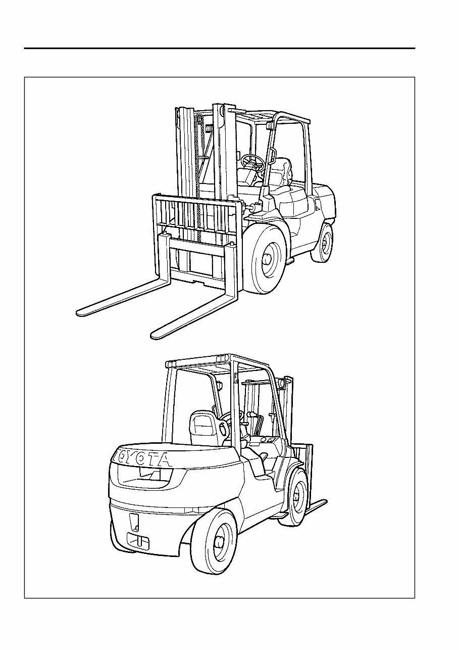
EXTERIOR VIEWS

0-3
VEHICLE MODEL
7FG35
02-7FG35
7FD35
02-7FD35
7FGK40
02-7FGK40
7FDK40
02-7FDK40
7FG40
02-7FG40
7FD40
02-7FD40
7FG45
02-7FG45
7FD45
02-7FD45
02-7FGA50
02-7FDA50
3.5 ton model
K4.0 ton model
4.0 ton model
4.5 ton model
5.0 ton model
3.5 ton series
4.0 ton series
4.5 ton series
5.0 ton series
M/T
T/C
M/T
T/C
M/T
T/C
M/T
T/C
M/T
T/C
M/T
T/C
M/T
T/C
M/T
T/C
T/C
T/C
Transmission Type Vehicle Model Engine
Model Series
Classification
Note:
The G4 engine is the same as the GM6-262 engine except for the nomenclature.
G4
(GM6-262)
G4
(GM6-262)
G4
(GM6-262)
G4
(GM6-262)
13Z
G4
(GM6-262)
13Z
13Z
13Z
13Z
Gasoline
Gasoline
Gasoline
Gasoline
Diesel
Gasoline
Diesel
Diesel
Diesel
Diesel
0-4
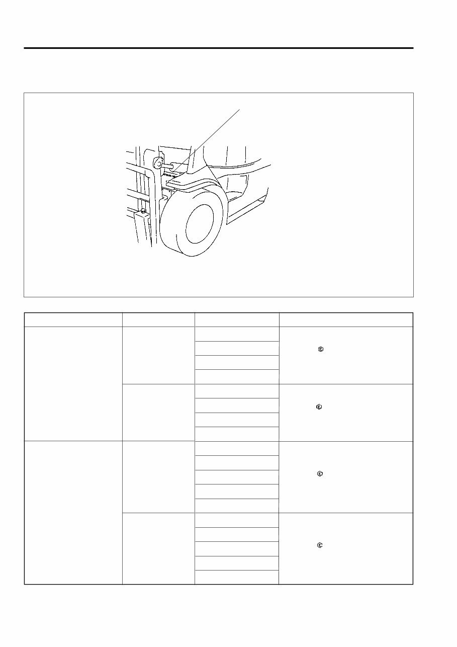
FRAME NUMBER
Frame No. Punching Position
Series Engine
G4(GM6-262)
13Z
G4(GM6-262)
13Z
Vehicle model
7FG35
02-7FG35
7FGK40
02-7FGK40
7FD35
02-7FD35
7FDK40
02-7FDK40
7FG40
02-7FG40
7FG45
02-7FG45
02-7FGA50
7FD40
02-7FD40
7FD45
02-7FD45
02-7FDA50
Punching format
EEC spec. models
7FGK40 10011
Other models
7FGK40-10011
EEC spec. models
7FDK40 10011
Other models
7FDK40-10011
EEC spec. models
7FGA50 10011
Other mod ls
7FGA50-10011
EEC spec. models
7FDA50 10011
Other models
7FDA50-10011
Punching position
Punching format
3.5
•
K4.0 ton model
4.0 ~ 5.0 ton model
0-5
HOW TO USE THIS MANUAL
EXPLANATION METHOD
1. Operation procedure
(1) The operation procedure is described in either pattern A or pattern B below.
Pattern A: Explanation of each operation step with illustration.
Pattern B: Explanation of operation procedure by indicating step numbers in one illustration, fol-
lowed by explanation of cautions and notes summarized as point operations.
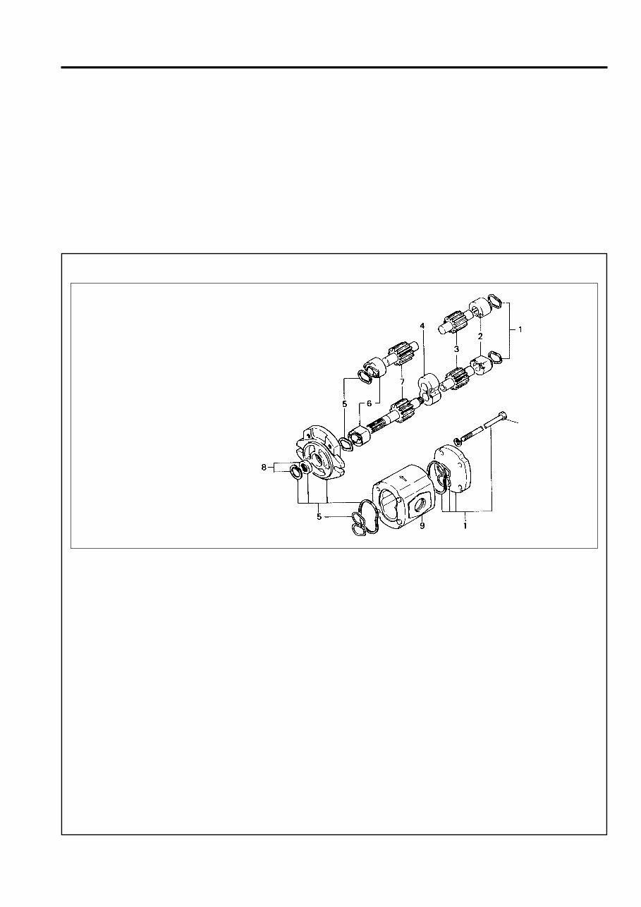
Example of description in pattern B
DISASSEMBLY·INSPECTION·REASSEMBLY Tightening torque unit T = N·m (kgf-cm) [ft-lbf]
Disassembly Procedure
1 Remove the cover. [Point 1]
2 Remove the bushing [Point 2] Operation explained later
3 Remove the gear.
Point Operations Explanation of key point for operation with an illustration
[Point 1]
Disassembly: Put a match mark when removing the pump cover.
[Point 2]
Inspection: Measure the bush inside diameter.
Limit: 19.12 mm (0.7528 in)
• Step Nos. are partially sometimes
omitted in illustrations.
• When a part requiring tightening
torque instruction is not indicated in
the illustration, the part name is de-
scribed in the illustration frame.
T = 46.1 ~ 48.1
(470 ~ 490)
[34.0 ~ 35.5]
0-6
Abbreviation (code)
ASSY
LH
LLC
M/T
OPT
O/S
PS
RH
SAE
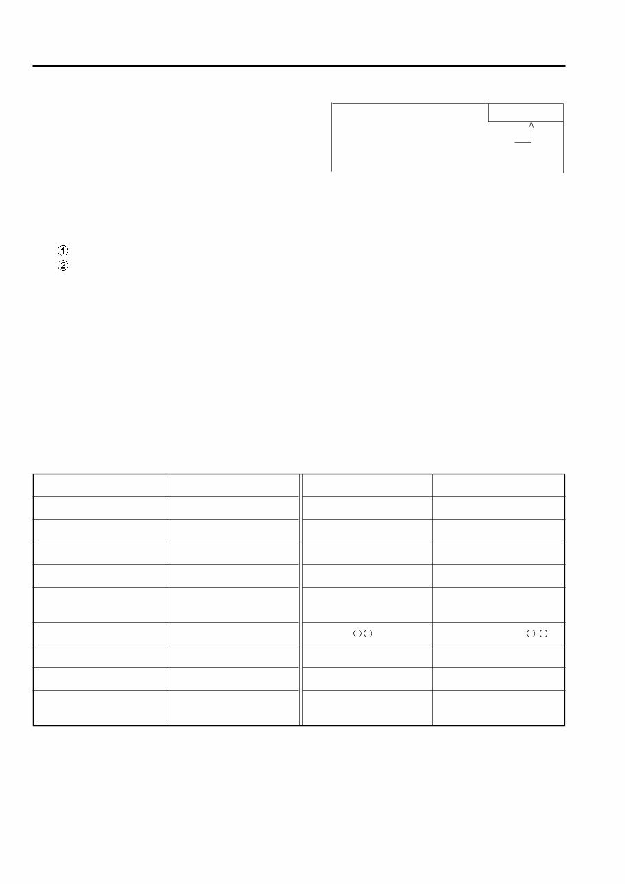
2. How to read components figures (Example)
(1) The components figure uses the illustration
in the parts catalog for the vehicle model.
Please refer to the catalog for checking the
part name.
The number at the right shoulder of each
components figure indicates the Fig. num-
ber in the parts catalog.
3. Matters omitted in this manual
(1) This manual omits description of the following jobs, but perform them in actual operation:
Cleaning and washing of removed parts as required
Visual inspection (partially described)
TERMINOLOGY
Caution:
Important matters of which negligence may cause accidents. Be sure to abserve them.
Note:
Important items of which negligence may cause accidents, or matters in operation procedure
requiring special attention.
Standard: Values showing allowable range in inspection and adjustment.
Limit: Maximum or minimum allowable value in inspection or adjustment.
ABBREVIATIONS
Meaning
System of active stability
Special service tool
Standard
Tightening torque
Torque converter &
transmission
Number of teeth ( )
Undersize
With
Less
Meaning
Assembly
Left hand
Long life coolant
Manual transmission
Option
Oversize
Power steering
Right hand
Society of Automotive
Engineers (USA)
Abbreviation (code)
SAS
SST
STD
T =
T/C
T
U/S
W/
L/
-
FIG number in parts catalog
3201
0-7
OPERATIONAL TIPS
1. Safe operation
(1) After jacking up, always support with wooden blocks or rigid stands.
(2) When hoisting the vehicle or its heavy component, use wire rope(s) with a sufficient reserve in load
capacity.
(3) Always disconnect the battery terminal before the inspection or servicing of electrical parts.
2. Tactful operation
(1) Prepare the mechanic tools, necessary measuring instruments (circuit tester, megger, oil pressure
gauge, etc.) and SSTs before starting operation.
(2) Before disconnecting wiring, always check the cable color and wiring state.
(3) When overhauling functional parts, complicated portions or related mechanisms, arrange the parts
neatly to prevent confusion.
(4) When disassembling and inspecting such a precision part as the control valve, use clean tools and
operate in a clean location.
(5) Follow the described procedures for disassembly, inspection and reassembly.
(6) Replace, gaskets, packings and O-rings with new ones each time they are disassembled.
(7) Use genuine Toyota parts for replacement.
(8) Use specified bolts and nuts. Observe the specified tightening torque at the time of reassembly.
Tighten to the center of the specified tightening torque range.
If no tightening torque is specified, tighten the bolt or nut according to the standard tightening torque
table.
3. Grasping the trouble state
When a trouble occurs, do not attempt immediate disassembly or replacement but first check if the
trouble requires disassembly or replacement for remedying.
4. Disposal of waste fluid, etc.
When draining waste fluid from the vehicle, receive it in a container.
If any oil, fuel, coolant, oil filter, battery or other harmful substance is directly discharged or scrapped
without permission, it will either adversely affect human health or destroy the environment. Always
sort waste fluids, etc. and treat them properly by requesting disposal by specialized companies.
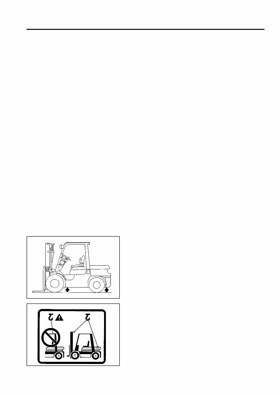
5. Jack up points
Front side:
Jack up at the bottom surface of the frame.
Rear side:
Jack up at the under the counterweight.
HOISTING THE VEHICLE
When hoisting the vehicle, sling with wire rope(s) at the mast
hook holes and the counterweight hook holes.
0-8
CIRCUIT TESTER
Circuit testers are available in both the analog and digital types. They should be used selectively according
to the purpose of measurement.
Analog type: This type is convenient for observing movement during operation, but the measured value
should only be used for reference or rough judgement.
Digital type: Fairly accurate reading is possible, but it is difficult to observe the variation or movement.
1. Difference in measurement results with the digital type and analog type
* The result may be different between measurements with the analog type and digital type.
Always use a circuit tester according to its operation manual.
Cautions when the polarities are different between the analog type and digital type are described
below.
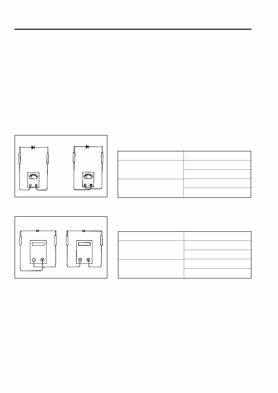
(1) Analog circuit tester
(2) Digital circuit tester
Measurement result example
Tester range: kΩ range
Analog type
Continuity exists
11 kΩ
No continuity
Forward
Reverse
Measurement result example
Tester range: MΩ range
Digital type
No continuity
1
Continuity exists
2 MΩ
Forward
Reverse
∞
Forward direction
Forward direction
Reverse direction
Reverse direction
You're Reading a Preview
What's Included?
Fast Download Speeds
Online & Offline Access
Access PDF Contents & Bookmarks
Full Search Facility
Print one or all pages of your manual
$37.99
Viewed 65 Times Today


Secure transaction
What's Included?
Fast Download Speeds
Online & Offline Access
Access PDF Contents & Bookmarks
Full Search Facility
Print one or all pages of your manual
$37.99
Get access to the comprehensive Original Illustrated Factory Workshop Service Manual for Toyota LPG Forklift Truck Type 7FG. This manual is a valuable resource for both professional mechanics and DIY enthusiasts, providing high-quality images, circuit diagrams, and detailed instructions for the operation, maintenance, and repair of your forklift truck.
Language: English
Manuals included:
- Main Service manual, 733 Pages
- GENERAL
- ENGINE
- CLUTCH
- TORQUE CONVERTER & TRANSMISSION
- MANUAL TRANSMISSION
- PROPELLER SHAFT
- DIFFERENTIAL
- FRONT AXLE
- REAR AXLE
- STEERING
- BRAKE
- BODY
- MATERIAL HANDLING SYSTEM
- MAST
- CYLINDER
- OIL PUMP
- OIL CONTROL VALVE
- SAS
- APPENDIX
- Operator Presence Sensing (OPS) Service manual, 145 Pages
- GENERAL
- OIL CONTROL VALVE
- MINI LEVER
- SAS
- APPENDIX
- Mini Lever Service manual, 106 Pages
- GENERAL
- OIL CONTROL VALVE
- MINI LEVER (OPT)
- SAS


