Toyota Electric Forklift Truck 5FBC13, 5FBC15, 5FBC18, 5FBC20, 5FBC25, 5FBC28, 5FBC30 Workshop Service Manual
What's Included?
Lifetime Access
Fast Download Speeds
Online & Offline Access
Access PDF Contents & Bookmarks
Full Search Facility
Print one or all pages of your manual
RETURN TO: MAIN INDEX RETURN TO: SERVICE MANUAL INDEX GENERAL BATTERY CONTROL CIRCUIT MULTIDISPLAY FUNCTIONS ELECTRICAL SYSTEM TROUBLESHOOTING MOTOR DRIVE UNIT FRONT AXLE REAR AXLE STEERING BRAKE BODY AND FRAME MATERIAL HANDLING SYSTEM MAST CYLINDER OIL PUMP OIL CONTROL VALVE APPENDIX 5FBC13-30
FOREWORD This manual covers the service procedures of the TOYOTA BATTERY FORKLIFT 5FBC13 - 30 Series. Please use this manual for providing quick, correct servicing of the corresponding forklift models. This manual deals with the above models as of November 1991. Please understand that disagreement can take place between the descriptions in the manual and actual vehicles due to change in design and specifi - cations. Any change or modifications thereafter will be informed by Toyota Industrial Vehicles' Parts & Service News. TOYOTA MOTOR CORPORATION
SECTION INDEX 1 NAME 1 SECTION 0 8 BATTERY CONTROL CIRCUIT MULTIDISPLAY FUNCTIONS ELECTRICAL SYSTEM TROUBLESHOOTING A DRIVE UNIT FRONT AXLE REAR AXLE STEERING BRAKE 8 BODY & FRAME MATERIAL HANDLING SYSTEM MAST CYLINDER OIL PUMP OIL CONTROL VALVE APPENDIX
GENERAL Page .............................................. EXTERIOR VIEWS 0-2 VEHICLE MODEL ................................................ 0-3 FRAME NUMBER ................................................ 0-4 ......................... HOW TO READ THIS MANUAL 0-5 EXPLANATION METHOD ..................................... 0-5 TERMINOLOGY .................................................. 0-6 ABBREVIATIONS ............................................... 0-6 LIST OF ABBREVIATIONS AND SYMBOLS ............. 0-7 OPERATIONAL TIPS ........................................ 0-8 CIRCUIT TESTER ............................................... 0-9 STANDARD BOLT & NUT TIGHTENING .......................................................... TORQUE 0-11 BOLT STRENGTH TYPE IDENTIFICATION METHOD ........................................................ 0 -11 TIGHTENING TORQUE TABLE ............................... 0-12 PRECOAT BOLTS ............................................... 0-13 HIGH PRESSURE HOSE FITTING .................................... TIGHTENING TORQUE 0-13 WIRE ROPE SUSPENSION ANGLE LIST ............. 0-14 SAFE LOAD FOR EACH WlRE ROPE ...................................... SUSPENSION ANGLE 0-14 COMPONENTS WEIGHT .................................... 0-15 RECOMMENDED LUBRICANTS ........................................... AND CAPACITIES 0 -16 ....................................... LUBRICATION CHART 0 -17 ................................. PERIODIC MAINTENANCE 0-18 PERIODIC REPLACEMENT OF PARTS AND LUBRICANTS .......................................... 0-23
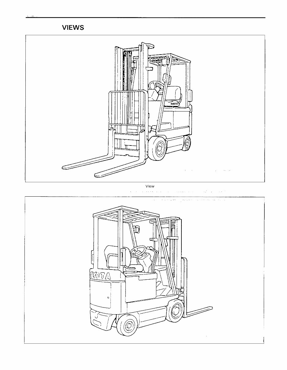
EXTERIOR VIEWS 1 1 I Front V~ew I I Rear View
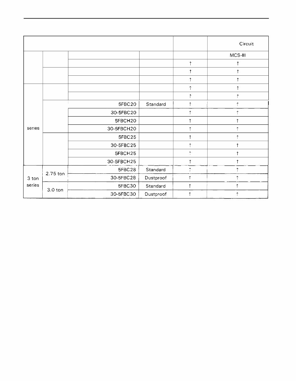
0 - 3 VEHICLE MODEL Model Voltage v 36 or 48 t T t T t Control Circu~t MCS-Ill t t T t t 2 ton series I ton series 1.25 ton 1.5 ton 1.75 ton 5FBC 1 3 . 30-5FBC 1 3 5FBC 1 5 30-5FBC 1 5 5FBC 1 8 30-5FBC 18 Standard Dustproof Standard Dustproof Standard Dustproof 2.0 ton 2.5 ton 30-5FBC20 5FBCH20 30-5FBCH20 5FBC25 30-5FBC25 5FBCH25 30-5FBCH25 Dustproof Standard Dustproof Standard Dustproof Standard Dustproof t t t t t t t t 7 t t t t t
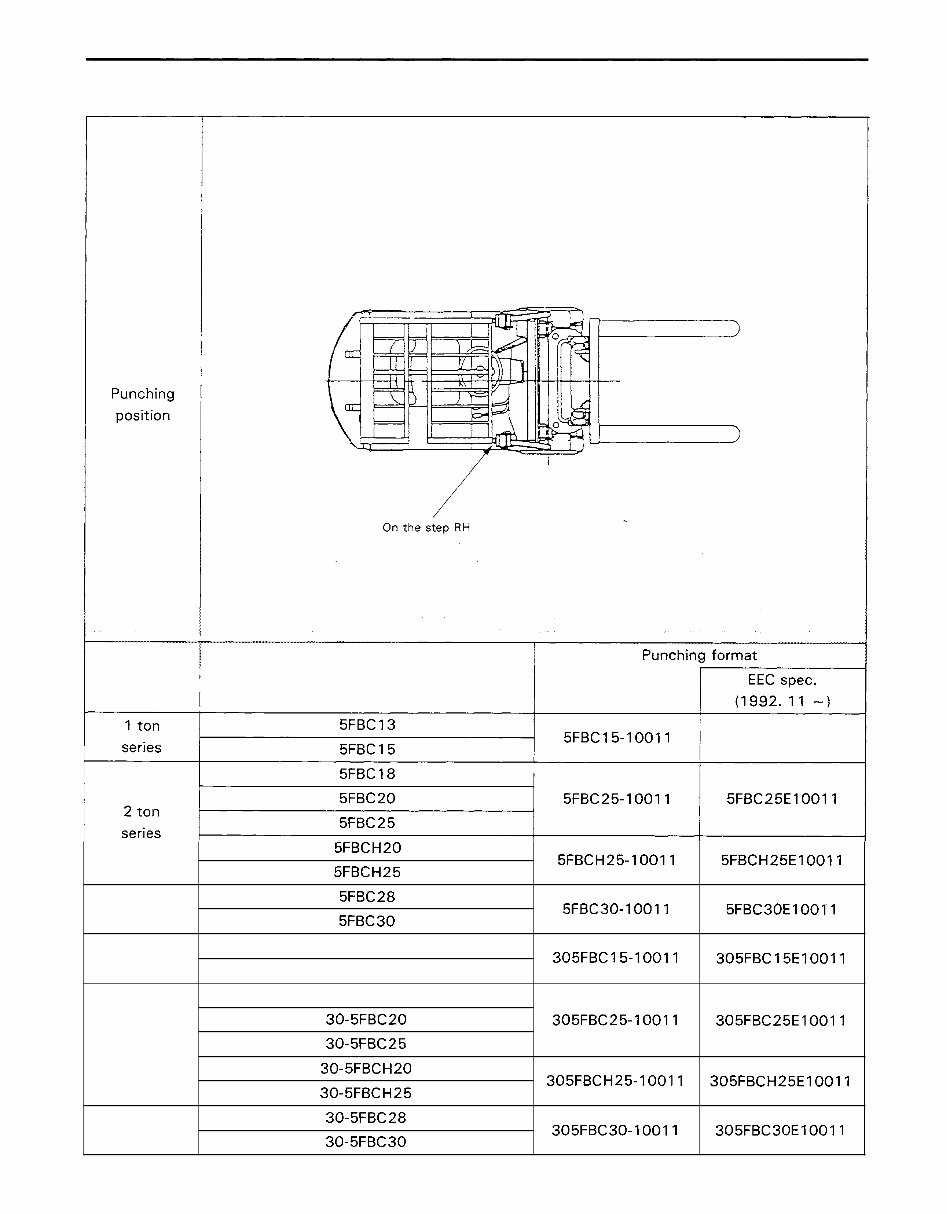
FRAME NUMBER Vehicle model 5FBC15-10011 5FBC 1 5E 1001 1 5FBC25-10011 5FBC25E10011 3 ton series 1 ton series 2 ton series 3 ton series 5FBCH20 5FBCH25 5FBC28 5FBC30 30- 5FBC 1 3 30- 5FBC 1 5 30- 5FBC I 8 30-5FBC20 30-5FBC25 30-5FBCH20 30-5FBCH25 30-5FBC28 30-5FBC30 5FBCH25-10011 5FBC30-10011 305FBC15-10011 305FBC25-10011 305FBCH25-10011 305FBC30-10011 5FBCH25E10011 5FBC30E10011 305FBC15E10011 305FBC25E10011 305FBCH25E10011 305FBC30E10011
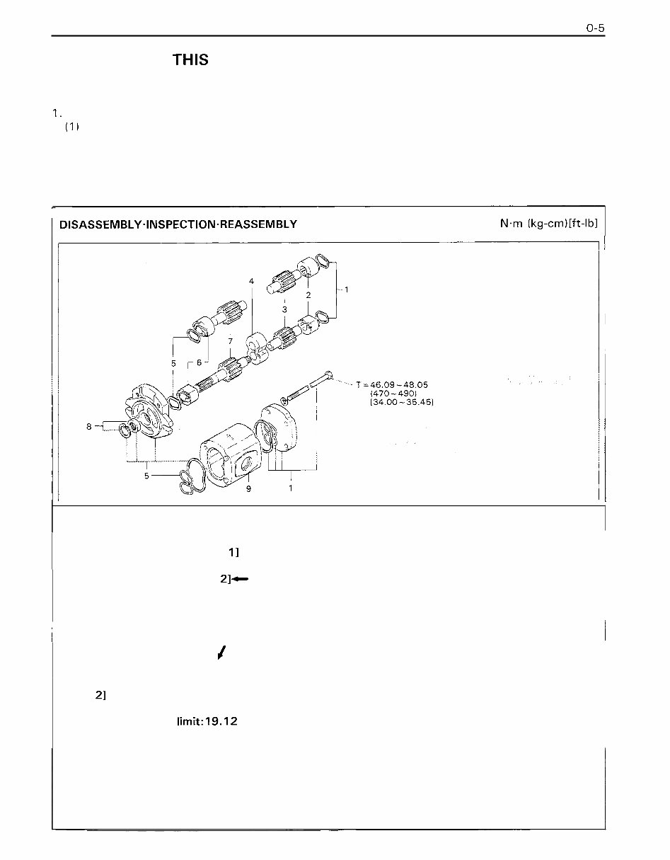
HOW TO READ THIS MANUAL EXPLANATION METHOD 1. Operation procedure (1 ) The operation procedure is described in either pattern A or pattern B below. Pattern A: Explanation of each operation step with a photo or illustration. Pattern B: Explanation of operation procedure by indicating step numbers in one illustration, fol - lowed by explanation of cautions and notes summarized as point operations. Example of description in pattern B / DISASSEMBLY-INSPECTION.REASSEMBLY Tightening torque unit T = N.m (kg-cm)[ft-lbl If a place or part cannot be indi - cated directly, the part name is described on the either side of the illustration. Example: 1 Piping I I Oil Pump Disassembly Procedure Disassembly Procedure 1 Remove the cover. [Point 11 2 Remove the bush [Point 21- Operation explained on a laterpage 3 Remove the gear. / Point operations Explanation of key point for operation with an illustration I [Point I I 4 Disassembly: Put a match mark when removing the pump cover. [Point 21 Inspection: Measure the bush inside diameter. Bush inside diameter limit:19.12 mm (0.7528 in)
2. How to read components figures (Example) (1) The components figure use the illustra- tion in the parts catalog for the vehicle model. Please refer to the catalog for checking the part name. The number at the right shoulder of each components figure indicates the Fig. number in the parts catalog. FIG number in parts catalog I 3. Matters omitted in this manual (1) This manual omits description of the following jobs, but perform them in actual operation: @ Cleaning and washing of removed parts as required @ visual inspection (Partially described) TERMINOLOGY Caution: lmportant matters of which negligence may cause accidents. Be sure to observe them. Note: lmportant items of which negligence may cause accidents or matters in operation procedure re- quiring special attention. Standard: Values showing allowable range in inspection and adjustment. Limit: Maximum or minimum allowable value in inspection or adjustment.
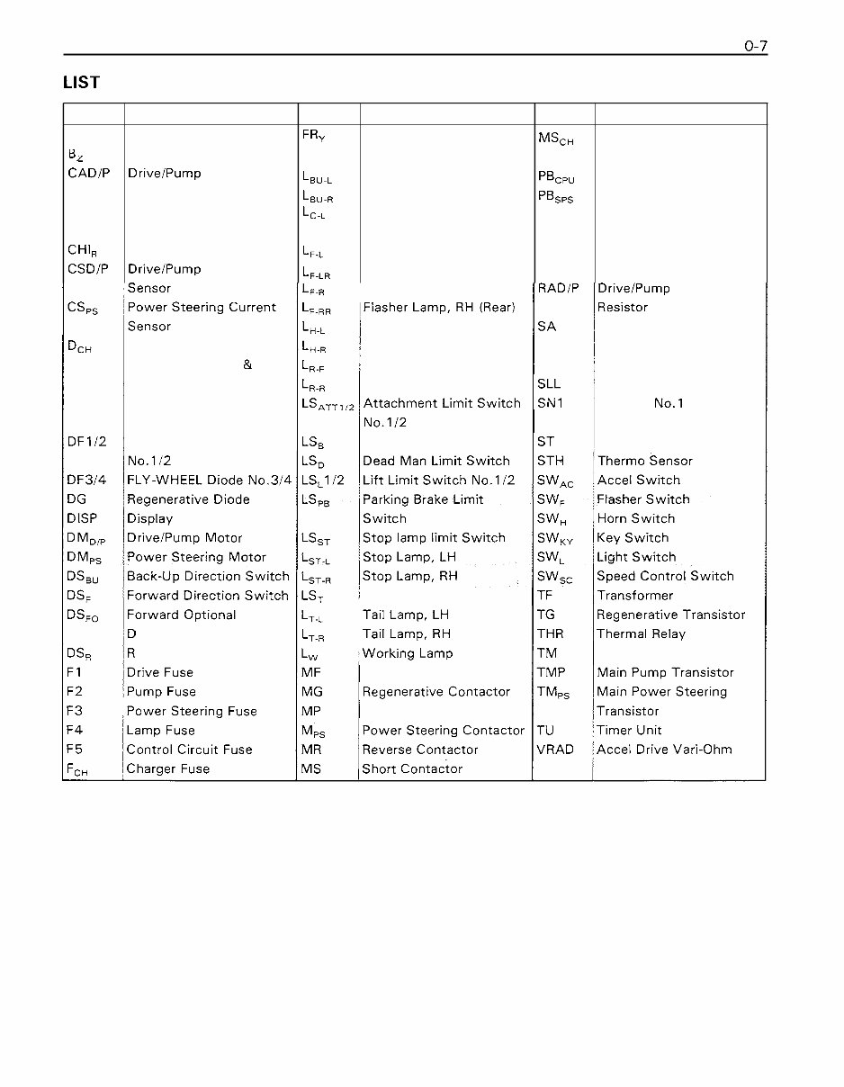
LIST OF ABBREVIATIONS AND SYMBOLS Symbol BATT B z CADIP CH CHI, CHIR CSDIP Flasher Lamp, RH RADIP Drivelpump Absorber Head Lamp, LH Surge Absorber DcH Charger Diode Head Lamp, RH SDD Drive SIT Driver DC-SDD DC-DC Converter & Rotaly Forward Lamp SDP Pump SIT Driver Source Drive (Drive) Rotaly Reverse Lamp Lequid Level Sensor DC-SDP DC-DC Converter & Snubber No.1 Source Drive (Pump) SSP Speed Sensor DF112 FLY-WHEEL Diode, Brake Limit Switch Steering Torque Sensor Tilt Limit Switch irection Switch everse Direction Switch Main Transistor Forward Contactor Pump Contactor Name Battery Buzzer Drivelpump Absorber Capacitor Charger Forward Chime Reverse Chime Drivelpump Current Name Charger Magnet Switch Field Weakning Contactor Computer Print Board SPS Print Board Working Pilot Lamp Fan Resistor Field Weakning Resistor Regenerative Resistor Symbol FRY H L , , . , L , , . , LC-L LF-L L , , , Name Flasher Relay Horn Back- up Lamp, LH Back- up Lamp, RH Clearance Lamp, LH Clearance Lamp, RH Flasher Lamp, LH Flasher Lamp, LH (Rear) Symbol MScH MW PBcpu PBsps PL , RF RFW RG
Get your hands on the Original Illustrated Factory Workshop Service Manual for Toyota Electric Forklift Truck 5FBC Series. This manual is a comprehensive resource for operating, maintaining, and repairing your forklift truck. It contains high-quality images, circuit diagrams, and detailed instructions to assist you in your endeavors.
Whether you are a professional mechanic or a DIY enthusiast, this manual is an invaluable tool. It covers a range of models including 5FBC13, 5FBC15, 5FBC18, 5FBC20, 5FBC25, 5FBC28, and 5FBC30. The manual is in English and spans 485 pages, providing extensive coverage of the subject matter.
The contents of the manual include:
General information such as exterior views, vehicle model, frame number, and terminology
Battery service standards, display indications, and troubleshooting
Control circuit details, including specifications, components, and adjustments
Multi-display functions, diagnosis, and analyzer usage
Electrical system troubleshooting and drive system/material handling system troubles
Drive unit, front axle, and rear axle specifications and components
Steering, brake, body & frame, and material handling system components and tests
Mast, cylinder, oil pump, oil control valve, and appendix with various lists and diagrams
This manual is an essential resource for anyone working with Toyota Electric Forklift Truck 5FBC Series. It provides detailed insights and instructions to ensure the smooth operation, maintenance, and repair of your forklift truck.
Recently Viewed
5,521,897Happy Clients
2,594,462eManuals
1,120,453Trusted Sellers
15Years in Business
Price:
Actual Price:
Toyota Electric Forklift Truck 5FBC13, 5FBC15, 5FBC18, 5FBC20, 5FBC25, 5FBC28, 5FBC30 Workshop Service Manual