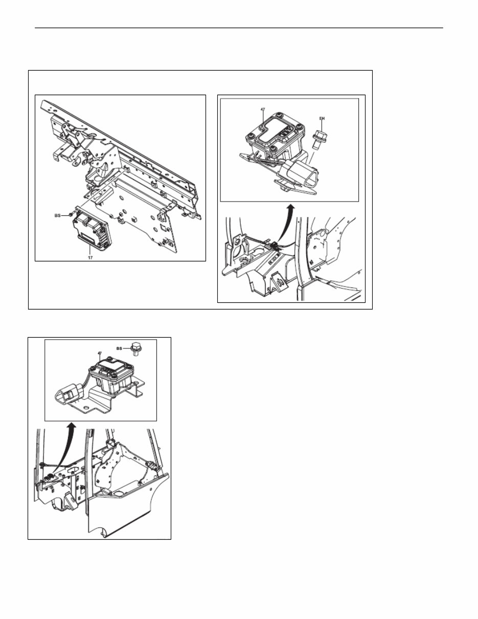
16-1 0 1 2 3 4 5 6 7 8 9 10 11 12 13 14 15 16 17 18 19 20 21 E SAS/OPS Page Page GENERAL .............................. 16-2 SAS FUNCTION .................... 16-4 COMPONENTS ....................... 16-4 PRECAUTIONS FOR REPAIR .............................. 16-10 SAS/OPS CONTROLLER REMOVAL·INSTALLATION...16-13 YAW RATE SENSOR REMOVAL·INSTALLATION...16-14 TIRE ANGLE SENSOR (OPT) REMOVAL·INSTALLATION...16-15 SWING LOCK CYLINDER REMOVAL·INSTALLATION...16-17 STEERING KNOB POSITION CORRECTING VALVE (OPT) REMOVAL·INSTALLATION...16-19 TILT ANGLE SENSOR REMOVAL·INSTALLATION...16-20 LOAD SENSOR REMOVAL·INSTALLATION...16-21 SPEED SENSOR REMOVAL·INSTALLATION...16-22 FORK HEIGHT SWITCH REMOVAL·INSTALLATION...16-23 FUNCTIONAL PARTS ............ 16-24 OPS FUNCTIONS ............... 16-25 GENERAL ............................ 16-25 CONTROL SPECIFICATION... 16-25 MATCHING .......................... 16-26 GENERAL ............................ 16-26 BEFORE STARTING MATCHING ........................ 16-27 OPTION SET ....................... 16-31 DIAGNOSIS MEMORY ........ 16-33 REAR WHEEL SWING CONTROL CHECK............ 16-34 SAS/OPS PLUG-IN ANALYZER ........................ 16-35
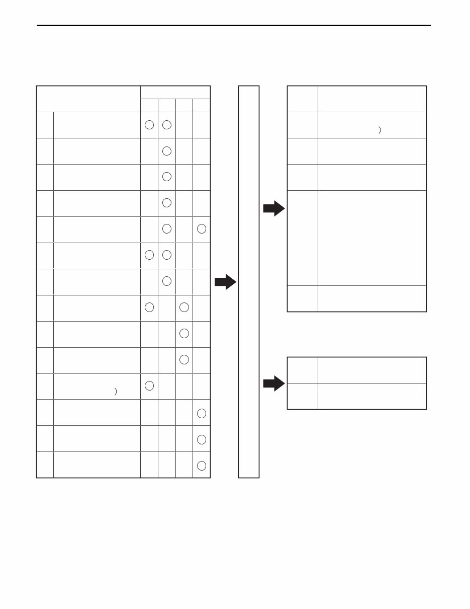
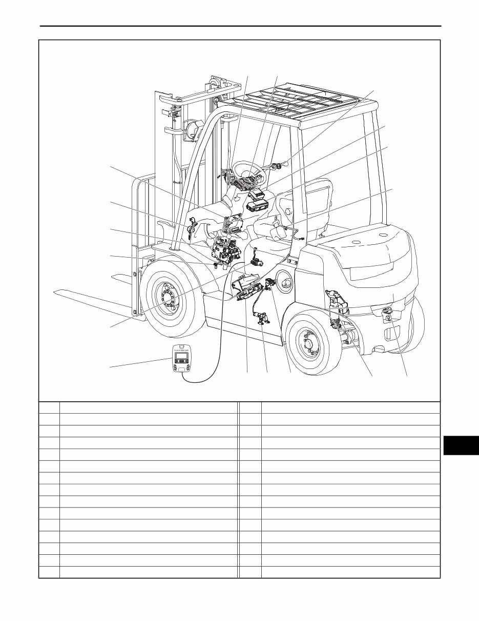
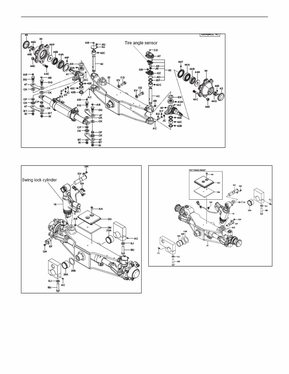
16-2 16-2 GENERAL SAS (System of Active Stability) /OPS (Operator Presence Sensing) system configuration Sensors are installed at each point of the vehicle to detect the vehicle movement and send signals to the controllers. These signals are controlled by the controllers, and sent to each actuator to be operated. (1) S T K Control Control S T K O S,T K,O Actuator Sensor O (2) (3) (4) (5) (6) (7) (8) (9) (10) (11) (12) (13) (14) Fork height switch Swing lock cylinder (Single tire only Tilt control valve Lift lock valve Knob position correcting valve Error lamp Error code display S :Rear wheel swing control T :Mast tilting control K :Steering knob position control (OPT) O:OPS control Forward interrupt relay Backward interrupt relay Unload valve Lift lock valve Backward tilt lock valve (Standard lever vehicle only) OPS lamp Buzzer* Tilt control valve Tilt angle sensor Forward tilt switch Backward tilt switch Lower switch Load sensor Fork automatic leveling switch Speed sensor Steering wheel angle sensor Tire angle sensor Yaw rate sensor (Single tire only Seat switch Forward switch Backward switch Controller Input Output S,T K,O S,T K,O Plug-in anallyzer (SST) Multifunction display DX (OPT) (Bilt-in analyzer) Output *: The OPS buzzer sounds only on the export model except "WITHOUT OPS BUZZER" specification. SAS / OPSS Section 16
Introducing the Toyota 8FDU Diesel Forklifts Service & Repair Manual – an original illustrated factory workshop manual designed specifically for Toyota Diesel Forklifts in the 8-Series, covering models 8FDU15, 8FDU18, 8FDU20, 8FDU25, 8FDU30, and 8FDU32. This manual features high-quality images, detailed circuit diagrams, and step-by-step instructions for operating, maintaining, and repairing your forklift.
All manuals are fully printable, contain searchable text, and include navigation bookmarks for ease of use. The content is in English.
Covered Models:
8FDU15
8FDU18
8FDU20
8FDU25
8FDU30
8FDU32
Included Files & Sections:
Sections 0-1.3, 620 pages
Sections 2-3, 190 pages
Sections 4-9, 224 pages
Sections 10-15, 176 pages
Sections 16-19-E, 690 pages
Repair Manual Supplement, 227 Pages (April 2010)
Contents Overview:
GENERAL 0
EXTERIOR VIEWS
VEHICLE MODEL
FRAME NUMBER
HOW TO USE THIS MANUAL
EXPLANATION METHOD
TERMINOLOGY
ABBREVIATIONS
OPERATIONAL TIPS
HOISTING THE VEHICLE
This comprehensive service and repair manual provides essential technical and practical information, specifically tailored for Toyota 8FDU Diesel Forklifts, ensuring accurate and efficient maintenance and repair for your equipment.
Reviews
Q&A
Recently Viewed
5,521,897Happy Clients
2,594,462eManuals
1,120,453Trusted Sellers
15Years in Business
Price:
Actual Price:
Toyota 8FDU Diesel Forklifts (8FDU15/8FDU18/8FDU20/8FDU25/8FDU30/8FDU32) Service & Repair Manual



 Lifetime Access




