

Toyota 5FB10, 5FB14, 5FB15, 5FB18, 5FB20. 5FB25, Full Service & Repair Manual
What's Included?
Fast Download Speeds
Online & Offline Access
Access PDF Contents & Bookmarks
Full Search Facility
Print one or all pages of your manual

RETURN TO: MAIN INDEX
RETURN TO: SERVICE MANUAL INDEX
GENERAL
CONTROL CIRCUIT
MULTIDISPLAY FUNCTIONS
ELECTRICAL SYSTEM TROUBLESHOOTING
MATERIAL HANDLING SYSTEM
MAST
CYLINDERS
APPENDIX
5FB10-30
FOREWORD
TOYOTA MOTOR CORPORATION
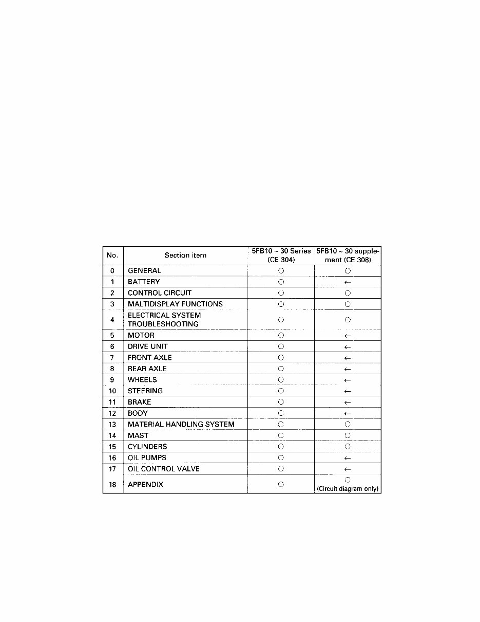
This manual covers the service procedures of the TOYOTA FORKLIFT
5FB10 ~ 30 series.
Since this manual describes alterations made in the vehicles being pro-
duced in January 1994, it is supplement to the existing repair manuals
for the 5FB10 ~ 30 series.
Any alterations after January 1994 will be announced in the Toyota
Parts & Service News.
Section Index
0-2
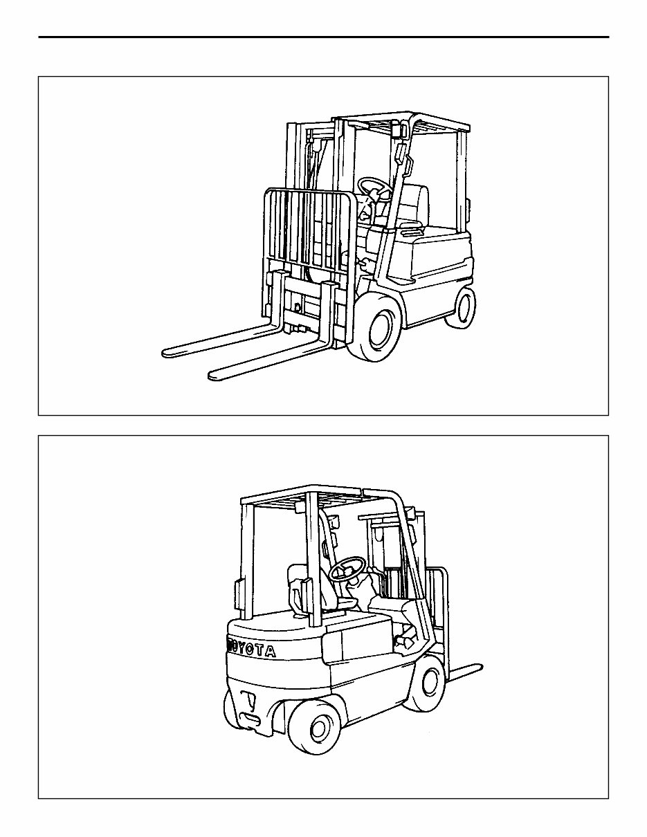
EXTERIOR VIEWS
0-3
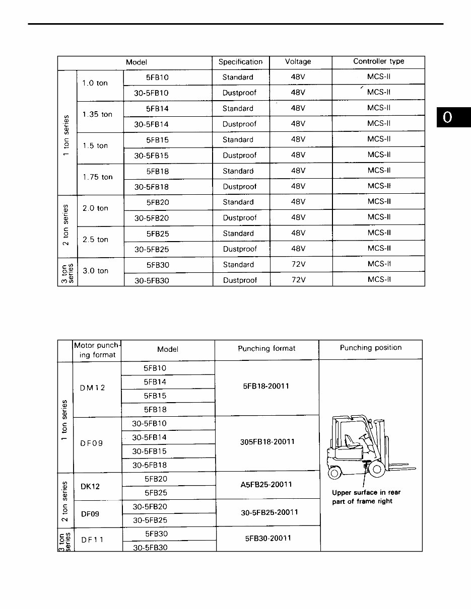
VEHICLE MODELS
FRAME NUMBER
0-4
HOW TO READ THIS MANUAL
EXPLANATION METHOD
Operation procedure
The operation procedure is described in either pattern A or pattern B below.
Pattern A: Explanation of each operation step with a photo or illustration.
Pattern B: Explanation of operation procedure by indicating step numbers in one illustration,
followed by explanation of cautions and notes summarized as point operations.
Example of description in pattern B
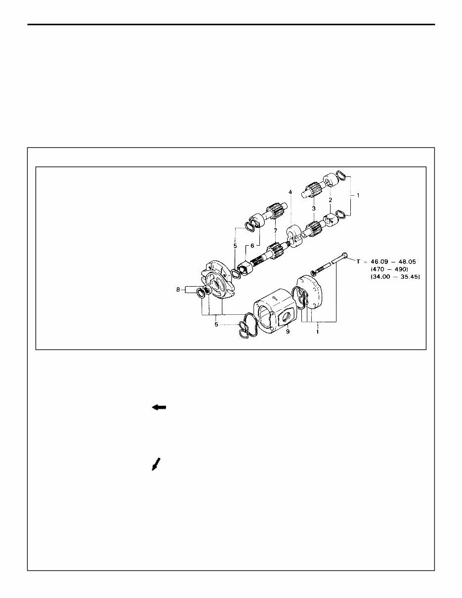
DISASSEMBLY·INSPECTION·REASSEMBLY Tightening torque unit T = N·m (kg-cm) [ft-lb]
If a place or part cannot be indicated
directly, the part name is described on
the either side of the illustration.
Example: 1 Piping
Disassembly Procedure
Remove the cover. [Point 1]
Remove the bush [Point 2] Operation explained later
Remove the gear.
Point operations Explanation of key point for operation with an illustration
[Point 1]
Disassembly: Put a match mark when removing the pump cover.
[Point 2]
Inspection: Measure the bush inside diameter.
Bush inside diameter limit: 19.12 mm (0.7528 in)
1.
(1)
1
2
3
0-5
How to read components figures (Example)
Matters omitted in this manual
This manual omits description of the following jobs, but perform them in actual operation:
Cleaning and washing of removed parts as required
Visual inspection (partially described)
TERMINOLOGY
Caution:
Important matters of which negligence may cause accidents. Be sure to observe them.
Note:
Important items of which negligence may cause accidents, or matters in operation procedure re-
quiring special attention.
Standard: Values showing allowable range in inspection and adjustment.
Limit: Maximum or minimum allowable value in inspection or adjustment.
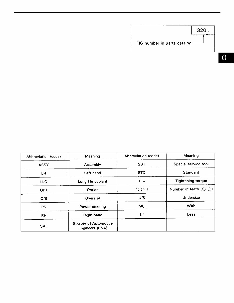
ABBREVIATIONS
The components figure uses the illustra-
tion in the parts catalog for the vehicle
model. Please refer to the catalog for
checking the part name.
The number at the right shoulder of each
components figure indicates the Fig. num-
ber in the parts catalog.
2.
3.
(1)
(1)
0-6
CIRCUIT TESTER
Circuit testers are available in both the analog and digital types. They should be used selectively ac-
cording to the purpose of measurement.
Analog type: This type is convenient for observing movement during operation, but the measured
value should only be used for reference or rough judgment.
Digital type: Fairly accurate reading is possible, but it is difficult to observe the variation or move-
ment.
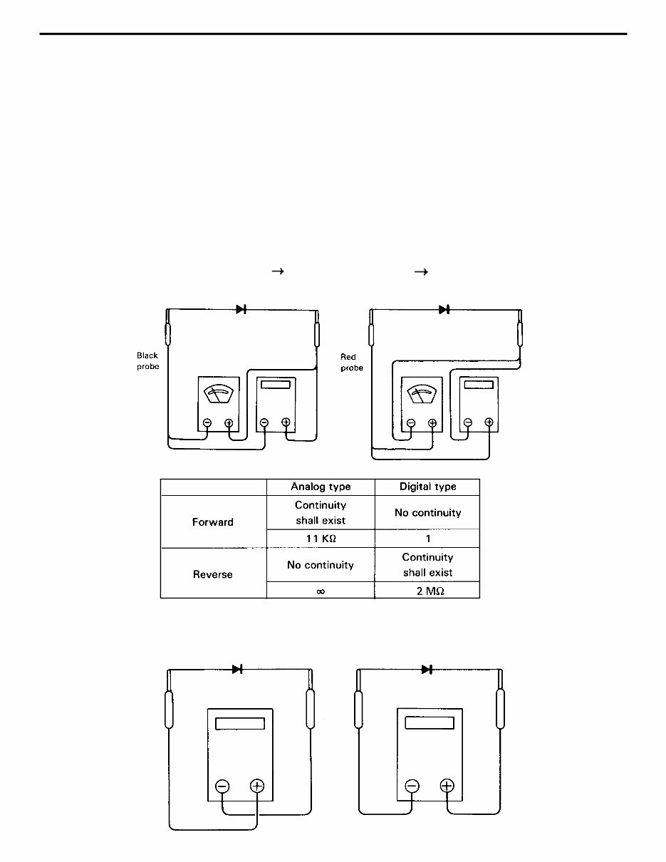
Difference in measurement results with the digital type and analog type
The result may be different between measurements with the analog type and digital type. Al-
ways use a circuit tester according to its operation manual. Cautions when the polarities are dif-
ferent between the analog type and digital type are described below.
Circuit tester range: Analog type kohm range Digital type 2 Mohm range
Forward direction Reverse direction
Measurement result example
As seen from the example above, the measurement results with the analog and digital types are re-
verse. In measurement with a digital type circuit tester, therefore, use the tester probes as shown be-
low.
Forward direction Reverse direction
1.
*
0-7
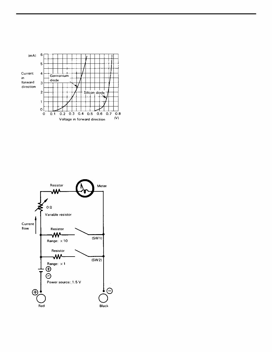
Difference in result of measurement with circuit tester
The circuit tester power supply voltage depends on the tester type. 1.5V, 3.0V or 6.0V is used.
The resistance of a semiconductor such as a diode varies with the circuit tester power supply
voltage.
The diode characteristics are shown in the figure below.
Difference in measurement result by measurement range (analog type)
In the analog type circuit tester, changing the measurement
range switches over the internal circuit to vary the circuit
resistance. Even when the same diode is measured, the
measurement result varies with the measurement range.
Always use the range described in the repair manual
for measurement.
2.
The resistance values of the same semiconductor mea-
sured with two types of circuit testers having different
power supply voltages are different.
This manual describes the results of measurement
with a circuit tester whose power supply voltage is
3.0 V.
0-8
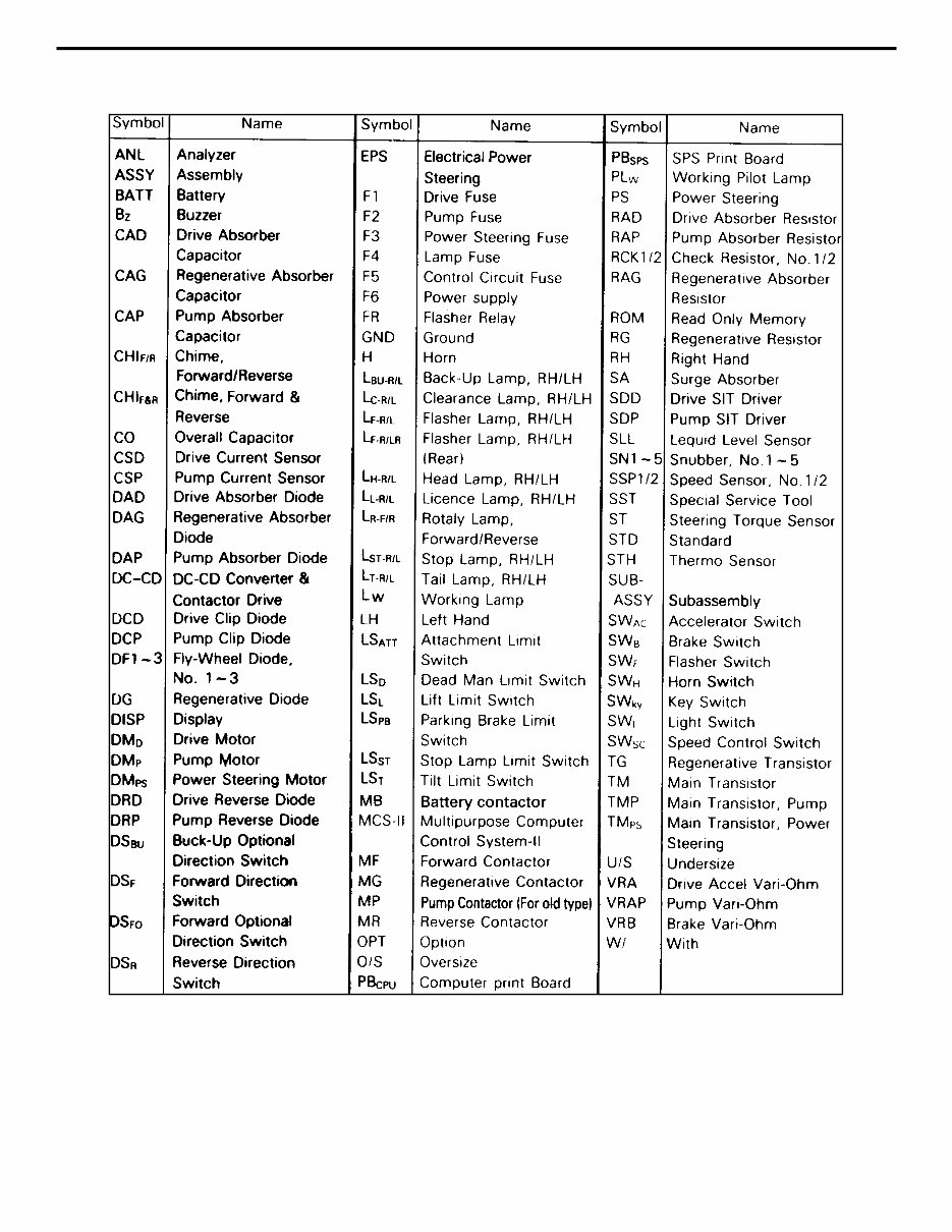
LIST OF ABBREVIATIONS AND SYMBOLS

0-9
OPERATIONAL TIPS
Safe operation
After jacking up, always support with rigid stands.
When hoisting the vehicle or its heavy component, use wire repe(s) with a sufficient reserve in
load capacity.
Always disconnect the battery plugs before the inspection or servicing of electrical parts.
Tactful operation
Prepare the mechanic tools, necessary measuring instruments (circuit tester, megger, oil pres-
sure gauge, etc.) and SSTs before starting operation.
Before disconnecting wiring, always check the cable color and wiring state.
When overhauling functional parts, complicated portions or related mechanisms, arrange the parts
neatly to prevent confusion.
When disassembling and inspecting such a precision part as the control valve, use clean tools
and operate in a clean location.
Follow the described procedures for disassembly, inspection and reassembly.
Replace, gaskets, packings and O-rings with new ones each time they are disassembled.
Use genuine Toyota parts for replacement.
Use specified bolts and nuts. Observe the specified tightening torque at the time of reassembly.
If no tightening torque is specified, tighten the bolt or nut according to the standard tightening
torque table.
Grasping the trouble state
When a trouble occurs, do not attempt immediate disassembly or replacement but first check if
the trouble requires disassembly or replacement for remadying.
1.
2.
3.
(1)
(2)
(3)
(1)
(2)
(3)
(4)
(5)
(6)
(7)
(8)
You're Reading a Preview
What's Included?
Fast Download Speeds
Online & Offline Access
Access PDF Contents & Bookmarks
Full Search Facility
Print one or all pages of your manual
$39.99
$51.99
Viewed 16 Times Today


Secure transaction
What's Included?
Fast Download Speeds
Online & Offline Access
Access PDF Contents & Bookmarks
Full Search Facility
Print one or all pages of your manual
$39.99
$51.99
- Complete Factory Service Repair Workshop Manual for Toyota 5FB10, 5FB14, 5FB15, 5FB18, 5FB20, 5FB25.
- Accessible for instant download to your computer, tablet, or smartphone.
- Includes detailed photos & diagrams, covering all repairs, servicing, and troubleshooting procedures.
- Utilized by professional mechanics and technicians, featuring step-by-step instructions and highly detailed exploded diagrams & pictures.
- Printable - You have the option to print out a single page or the entire manual.
- Multi-Device Usage - This manual can be used on multiple computers without limitations.
- No Expiry - This is the FULL Manual without any limitations, trial periods, or expiration, and can be used for life.
- Compatibility - Fully compatible with all Windows & MAC Computers.
Thanks for considering this manual. Click the button to proceed.


