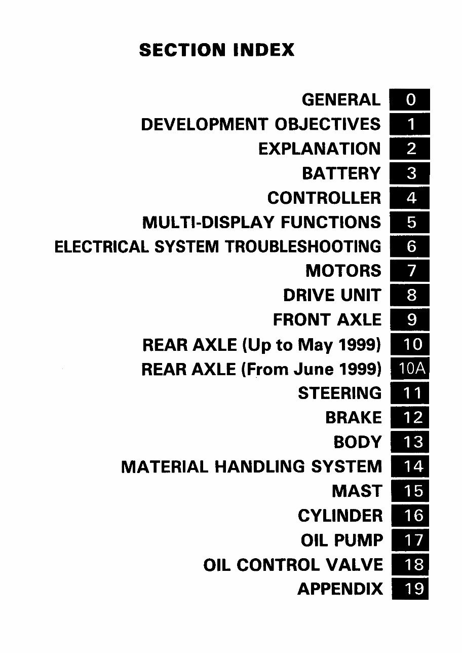
< Tillbaka till Index TOYOTA FBMF 16-30 SECTION INDEX GENERAL DEVELOPMENT OBJECTIVES EXPLANATION BATTERY CONTROLLER MULTI-DISPLAY FUNCTIONS ELECTRICAL SYSTEM TROUBLESHOOTING MOTORS DRIVE UNIT FRONT AXLE REAR AXLE (Up to May 1999) REAR AXLE (From June 1999) STEERING BRAKE BODY MATERIAL HANDLING SYSTEM MAST CYLINDER OIL PUMP OIL CONTROL VALVE APPENDIX
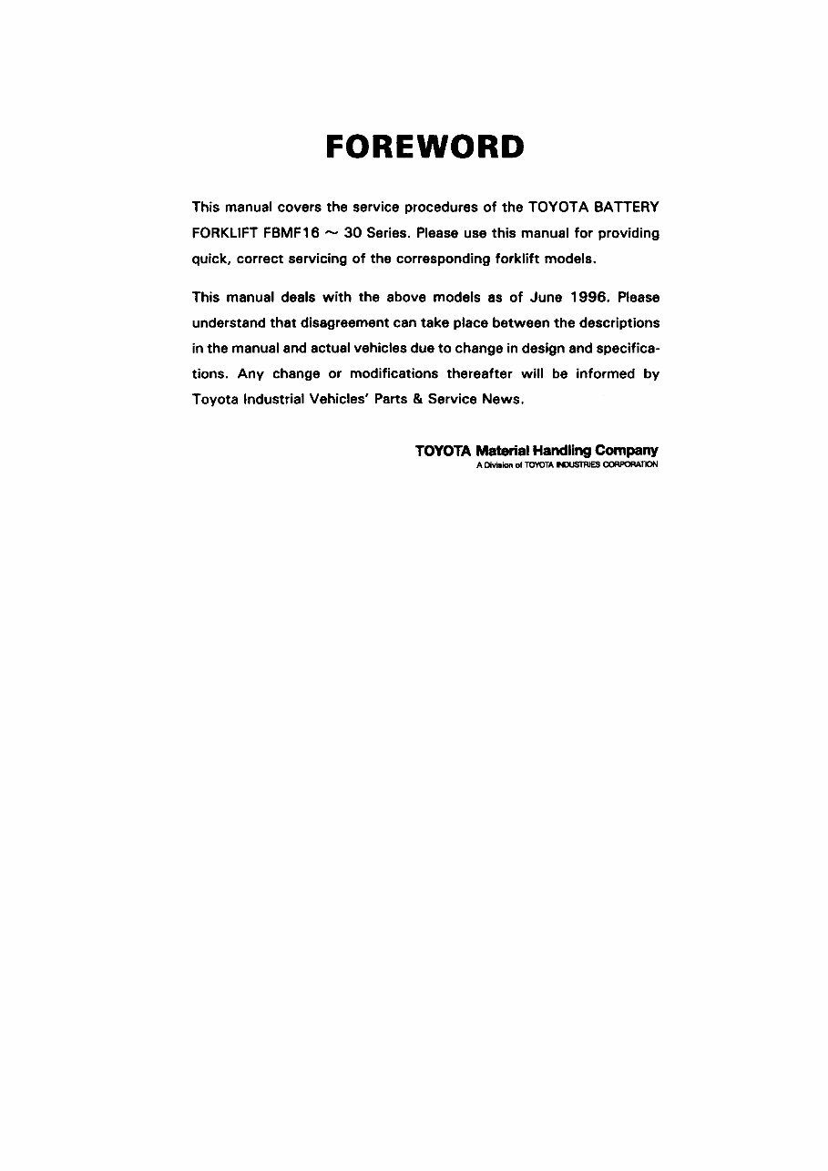
FOREWORD This manual covers the service procedures of the TOYOTA BATTERY FORKLIFT FBMF16 ~ 30 Series. Please use this manual for providing quick, correct servicing of the corresponding forklift models. This manual deals with the above models as of June 1996. Please understand that disagreement can take place between the descriptions in the manual and actual vehicles due to change in design and specifica¬ tions. Any change or modifications thereafter will be informed by Toyota Industrial Vehicles' Parts & Service News. TOYOTA Material Handling Company A Division of TOYOTA NDUSTRIES CORPORATION
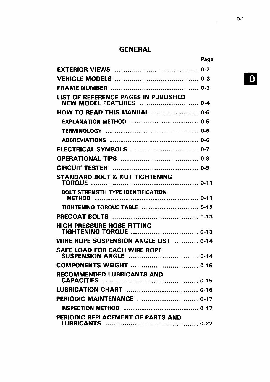
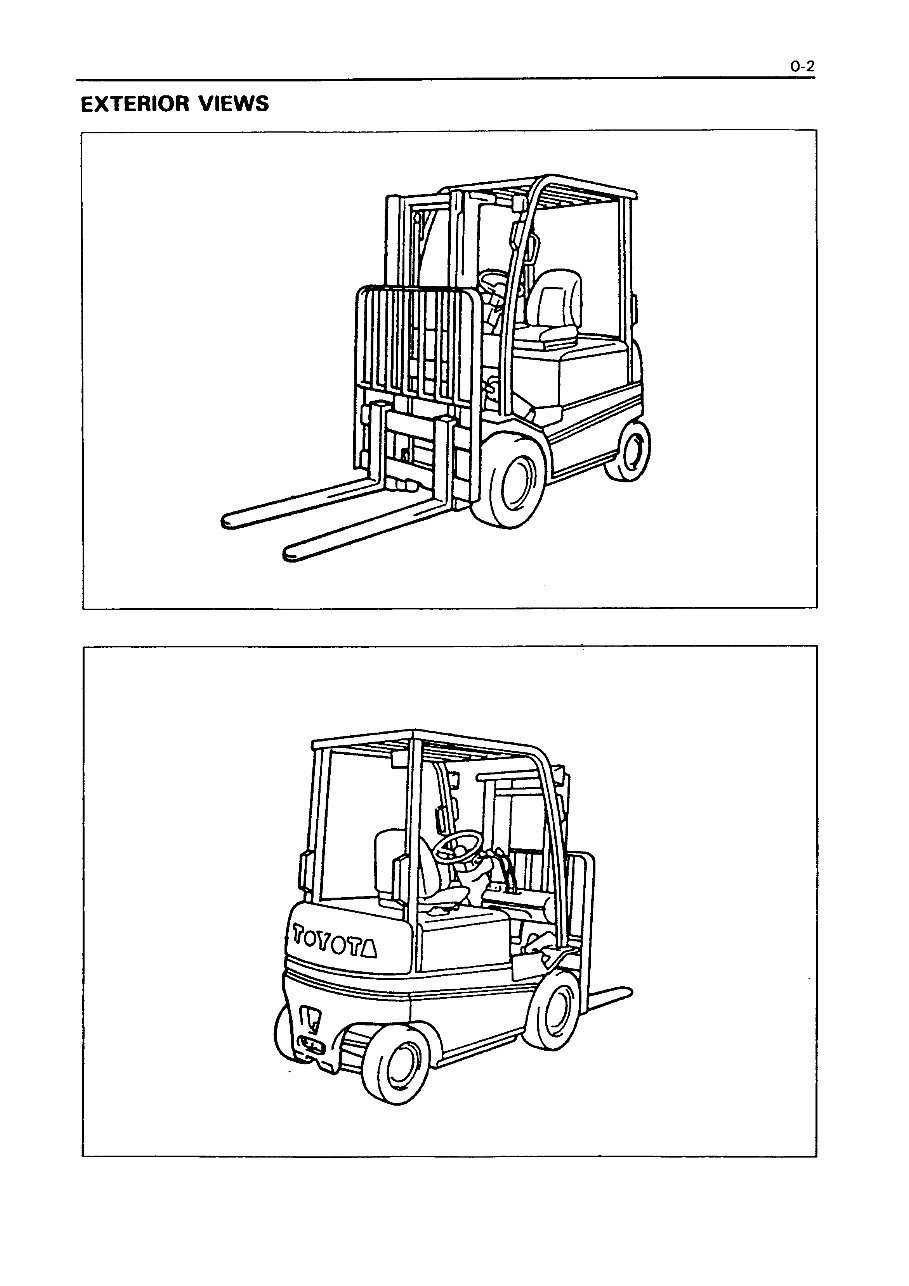
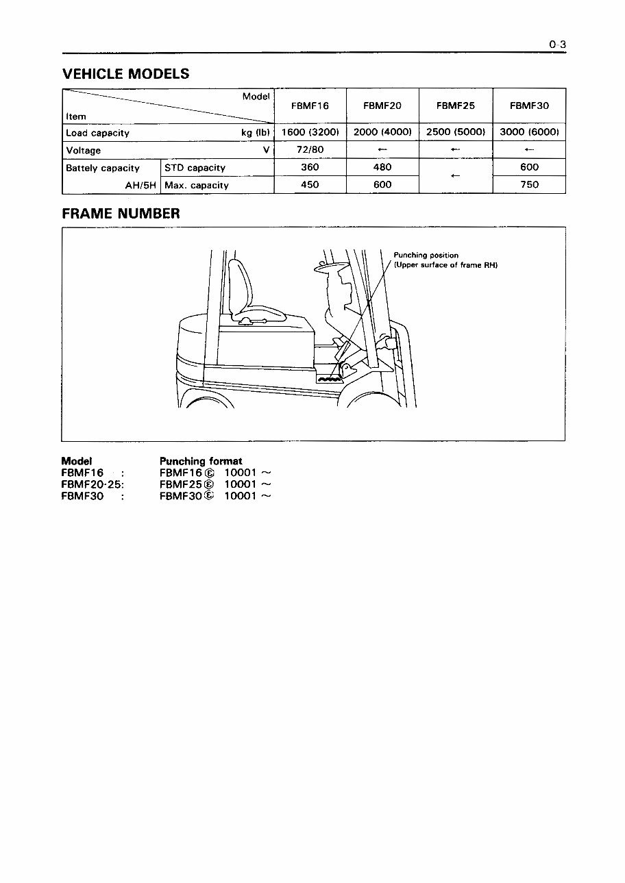
TOTALDOKUMENT, SERVICE ............................. 0-23 0-1 GENERAL Page EXTERIOR VIEWS 0-2 VEHICLE MODELS 0-3 FRAME NUMBER 0-3 LIST OF REFERENCE PAGES IN PUBLISHED NEW MODEL FEATURES 0-4 HOW TO READ THIS MANUAL 0-5 EXPLANATION METHOD 0-5 TERMINOLOGY 0-6 ABBREVIATIONS 0-6 ELECTRICAL SYMBOLS 0-7 OPERATIONAL TIPS 0-8 CIRCUIT TESTER 0-9 STANDARD BOLT & NUT TIGHTENING TORQUE 0-11 BOLT STRENGTH TYPE IDENTIFICATION METHOD 0-11 TIGHTENING TORQUE TABLE 0-12 PRECOAT BOLTS 0-13 HIGH PRESSURE HOSE FITTING TIGHTENING TORQUE 0-13 WIRE ROPE SUSPENSION ANGLE LIST 0-14 SAFE LOAD FOR EACH WIRE ROPE SUSPENSION ANGLE 0-14 COMPONENTS WEIGHT 0-15 RECOMMENDED LUBRICANTS AND CAPACITIES 0-15 LUBRICATION CHART 0-16 PERIODIC MAINTENANCE 0-17 INSPECTION METHOD 0-17 PERIODIC REPLACEMENT OF PARTS AND LUBRICANTS 0-22
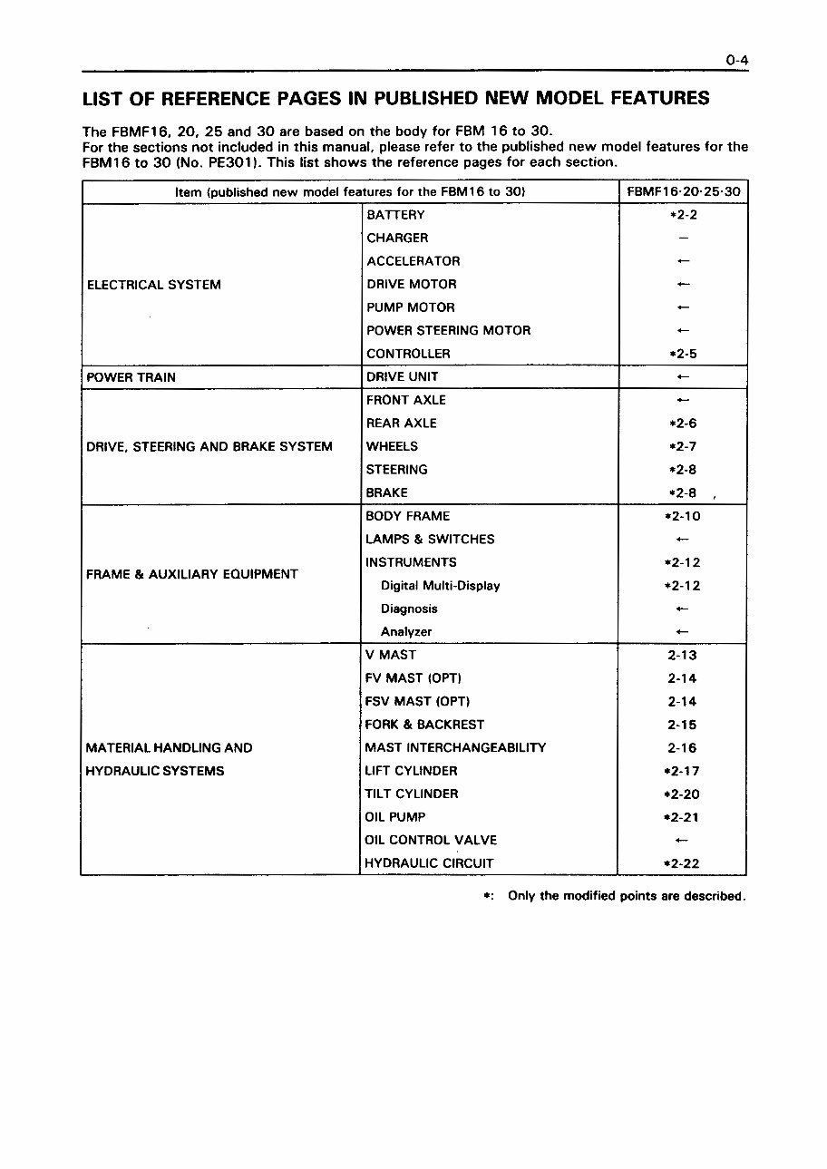
0-4 LIST OF REFERENCE PAGES IN PUBLISHED NEW MODEL FEATURES The FBMF16, 20, 25 and 30 are based on the body for FBM 16 to 30. For the sections not included in this manual, please refer to the published new model features for the FBM16 to 30 (No. PE301). This list shows the reference pages for each section. Item (published new model features for the FBM16 to 30) FBMF16-20-25-30 BATTERY *2-2 CHARGER - ACCELERATOR - ELECTRICAL SYSTEM DRIVE MOTOR - PUMP MOTOR - POWER STEERING MOTOR - CONTROLLER *2-5 POWER TRAIN DRIVE UNIT «- FRONT AXLE - REAR AXLE *2-6 DRIVE, STEERING AND BRAKE SYSTEM WHEELS *2-7 STEERING *2-8 BRAKE ÿ2-8 , BODY FRAME *2-10 LAMPS & SWITCHES «- FRAME & AUXILIARY EQUIPMENT INSTRUMENTS Digital Multi-Display *2-12 *2-12 Diagnosis - Analyzer - V MAST 2-13 FV MAST (OPT) 2-14 FSV MAST (OPT) 2-14 FORK & BACKREST 2-15 MATERIAL HANDLING AND MAST INTERCHANGEABILITY 2-16 HYDRAULIC SYSTEMS LIFT CYLINDER ÿ2-17 TILT CYLINDER *2-20 OIL PUMP *2-21 OIL CONTROL VALVE 4 — HYDRAULIC CIRCUIT *2-22 *: Only the modified points are described.
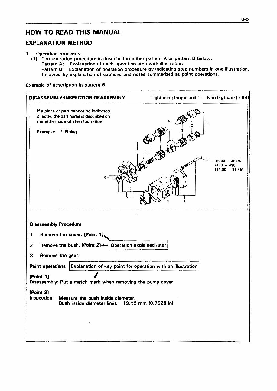
_ 0-5 HOW TO READ THIS MANUAL EXPLANATION METHOD 1. Operation procedure (1) The operation procedure is described in either pattern A or pattern B below. Pattern A: Explanation of each operation step with illustration. Pattern B: Explanation of operation procedure by indicating step numbers in one illustration, followed by explanation of cautions and notes summarized as point operations. Example of description in pattern B DISASSEMBLY-INSPECTION REASSEMBLY Tightening torque unit T = N m (kgf-cm) [ft-lbf] If a place or part cannot be indicated directly, the part name is described on the either side of the illustration. Example: 1 Piping r 6 J T = 46.09 - 48.05 (470 - 490I 134.00 - 35.451 Disassembly Procedure 1 Remove the cover. (Point 1 J, 2 Remove the bush. IPoint 2]-*- Operation explained laterj 3 Remove the gear. Point operations Explanation of key point for operation with an illustration [Point 1 ] / Disassembly: Put a match mark when removing the pump cover. [Point 2] Inspection: Measure the bush inside diameter. Bush inside diameter limit: 19.12 mm (0.7528 in)
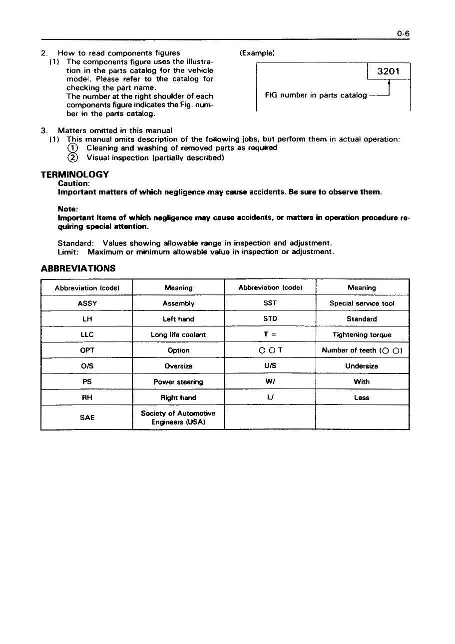
0-6 2. How to read components figures (1) The components figure uses the illustra¬ tion in the parts catalog for the vehicle model. Please refer to the catalog for checking the part name. The number at the right shoulder of each components figure indicates the Fig. num¬ ber in the parts catalog. (Example) 3201 FIG number in parts catalog 3. Matters omitted in this manual (1) This manual omits description of the following jobs, but perform them in actual operation: (T) Cleaning and washing of removed parts as required (2) Visual inspection (partially described) TERMINOLOGY Caution: Important matters of which negligence may cause accidents. Be sure to observe them. Note: Important items of which negligence may cause accidents, or matters in operation procedure re¬ quiring special attention. Standard: Values showing allowable range in inspection and adjustment. Limit: Maximum or minimum allowable value in inspection or adjustment. ABBREVIATIONS Abbreviation (code) Meaning Abbreviation (code) Meaning ASSY Assembly SST Special service tool LH Left hand STD Standard LLC Long life coolant T = Tightening torque OPT Option OOT Number of teeth (O O) O/S Oversize U/S Undersize PS Power steering w / With RH Right hand LI Less SAE Society of Automotive Engineers (USA)
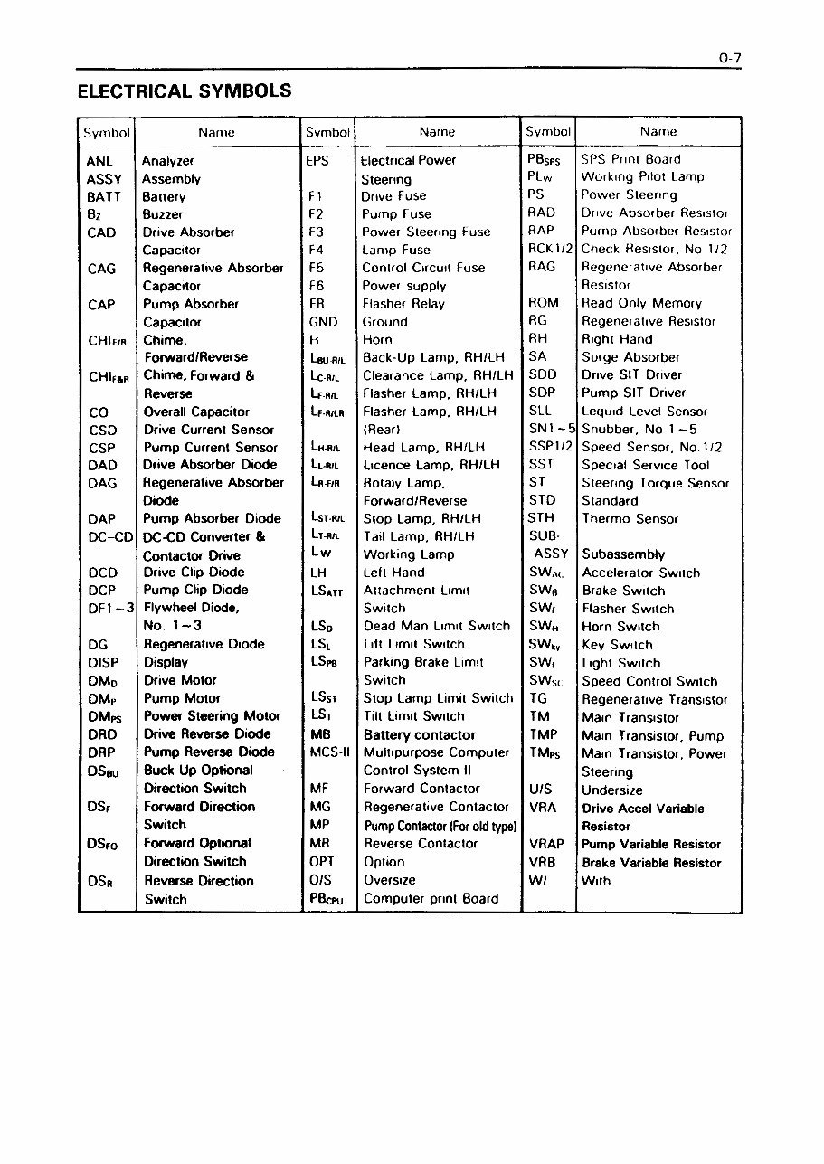
0-7 ELECTRICAL SYMBOLS Symbol Name Symbol Name Symbol Name ANL Analyzer EPS Electrical Power PBsps SPS Punt Board ASSY Assembly Steering PLw Working Pilot Lamp BATT Battery F 1 Drive Fuse PS Power Steering Bz Buzzer F2 Pump Fuse RAD Dove Absorber Resistor CAD Drive Absorber F3 Power Steering Fuse RAP Pump Absorber Resistor Capacitor F4 Lamp Fuse RCK1/2 Check Resistor. No 1/2 CAG Regenerative Absorber F5 Control Circuit Fuse RAG Regenerative Absorber Capacitor F6 Power supply Resistor CAP Pump Absorber FR Flasher Relay ROM Read Only Memory Capacitor GND Ground RG Regenerative Resistor CHIf/r Chime, H Horn RH Right Hand Forward/ Reverse Leu R/L Back-Up Lamp. RH/LH SA Surge Absorber CHIfsr Chime, Forward & Lc-r/l Clearance Lamp, RH/LH SDD Drive SIT Driver Reverse Lf R/L Flasher Lamp, RH/LH SDP Pump SIT Driver CO Overall Capacitor Lf-r/lr Flasher Lamp. RH/LH SLL Leguid Level Sensor CSD Drive Current Sensor (Rear) SN1 -5 Snubber, No 1 -5 CSP Pump Current Sensor Lh-r/l Head Lamp, RH/LH SSP1/2 Speed Sensor, No 1/2 DAD Drive Absorber Diode Llr/l Licence Lamp. RH/LH SST Special Service Tool DAG Regenerative Absorber Lrÿ/r Rotaly Lamp, ST Steering Torgue Sensor Diode Forward/Reverse STD Standard DAP Pump Absorber Diode LsT R/L Stop Lamp, RH/LH STH Thermo Sensor DC-CD DC-CD Converter & Lth/l Tail Lamp, RH/LH SUB Contactor Drive Lw Working Lamp ASSY Subassembly DCD Drive Clip Diode LH Left Hand SWA(. Accelerator Switch DCP Pump Clip Diode LSatt Attachment Limit sw« Brake Switch DPI -3 Flywheel Diode, Switch SWf Flasher Switch No. 1-3 LSd Dead Man Limit Switch SWH Horn Switch DG Regenerative Diode LSl Lift Limit Switch SWkv Key Switch DISP Display LSpb Parking Brake Limit SW, Light Switch DM0 Drive Motor Switch SWM Speed Control Switch DMr Pump Motor LSst Stop Lamp Limn Switch TG Regenerative Transistor DMps Power Steering Motor LSt Tilt Limit Switch TM Main Transistor DRD Drive Reverse Diode MB Battery contactor TMP Main Transistor. Pump DRP Pump Reverse Diode MCS II Multipurpose Computer TMps Main Transistor, Power DSeu Buck-Up Optional Control System-ll Steering Direction Switch MF Forward Contactor U/S Undersize DSf Forward Direction MG Regenerative Contactor VRA Drive Accel Variable Switch MP Pump Contactor (For old type) Resistor DSfo Forward Optional MR Reverse Contactor VRAP Pump Variable Resistor Direction Switch OPT Option VRB Brake Variable Resistor DSr Reverse Direction 0/S Oversize W/ With Switch PBcpu Computer print Board
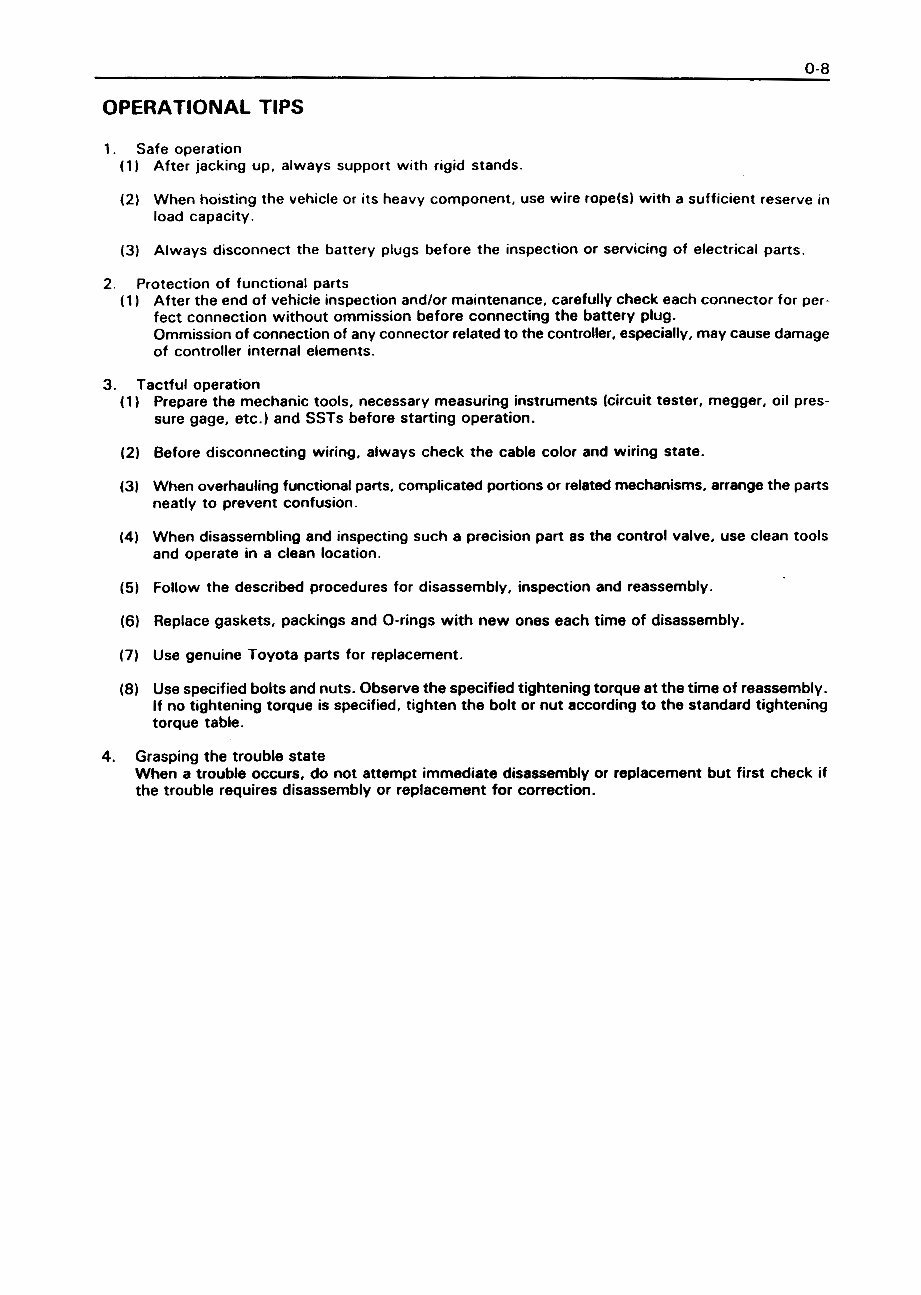
0-8 OPERATIONAL TIPS 1. Safe operation (1) After jacking up, always support with rigid stands. (2) When hoisting the vehicle or its heavy component, use wire rope(s) with a sufficient reserve in load capacity. (3) Always disconnect the battery plugs before the inspection or servicing of electrical parts. 2. Protection of functional parts (1) After the end of vehicle inspection and/or maintenance, carefully check each connector for per¬ fect connection without ommission before connecting the battery plug. Ommission of connection of any connector related to the controller, especially, may cause damage of controller internal elements. 3. Tactful operation (1) Prepare the mechanic tools, necessary measuring instruments (circuit tester, megger, oil pres¬ sure gage, etc.) and SSTs before starting operation. (2) Before disconnecting wiring, always check the cable color and wiring state. (3) When overhauling functional parts, complicated portions or related mechanisms, arrange the parts neatly to prevent confusion. (4) When disassembling and inspecting such a precision part as the control valve, use clean tools and operate in a clean location. (5) Follow the described procedures for disassembly, inspection and reassembly. (6) Replace gaskets, packings and 0-rings with new ones each time of disassembly. (7) Use genuine Toyota parts for replacement. (8) Use specified bolts and nuts. Observe the specified tightening torque at the time of reassembly. If no tightening torque is specified, tighten the bolt or nut according to the standard tightening torque table. 4. Grasping the trouble state When a trouble occurs, do not attempt immediate disassembly or replacement but first check if the trouble requires disassembly or replacement for correction.
You're Reading a Preview
What's Included?
Lifetime Access
Fast Download Speeds
Online & Offline Access
Access PDF Contents & Bookmarks
Full Search Facility
Print one or all pages of your manual
$37.99
Toyota (BT) Electric Forklift Truck: FBMF16, FBMF20, FBMF25, FBMF30 Workshop Service Manual
Get your hands on the Original Illustrated Factory Workshop Service Manual for Toyota (BT) Electric Forklift Truck. This manual is a comprehensive guide containing high-quality images, circuit diagrams, and detailed instructions to assist you in the operation, maintenance, and repair of your forklift truck. The manual is printable, searchable, and equipped with navigation bookmarks for easy access.
Covered models: FBMF16, FBMF20, FBMF25, FBMF30
Format: 495 Pages
Language: English
The manual covers a wide range of topics, including general information, exterior views, vehicle models, frame numbers, new model features, terminology, abbreviations, operational tips, circuit tester, bolt and nut tightening torque, bolt strength type identification method, tightening torque table, recommended lubricants and capacities, periodic maintenance, battery, controller, multi-display functions, electrical system troubleshooting, motors, drive unit, front axle, rear axle, steering, brake, body, material handling system, mast, cylinder, oil pump, oil control valve, and appendix. It also provides detailed explanations, inspection methods, periodic replacement of parts and lubricants, development objectives, and safe load information for wire rope suspension angles.
Whether you are a professional mechanic or a DIY enthusiast, this manual is an invaluable resource for maintaining and repairing your Toyota (BT) Electric Forklift Truck.
Reviews
Q&A
Recently Viewed
5,521,897Happy Clients
2,594,462eManuals
1,120,453Trusted Sellers
15Years in Business
Price:
Actual Price:
Toyota (BT) Electric Forklift Truck: FBMF16, FBMF20, FBMF25, FBMF30 Workshop Service Manual


 Lifetime Access




