TOYOTA Electric POWERED Forklift 7FBCU15-55 & 7FBCHU25 Service Repair Manual
What's Included?
Lifetime Access
Fast Download Speeds
Online & Offline Access
Access PDF Contents & Bookmarks
Full Search Facility
Print one or all pages of your manual
FOREWORD This Manual contains specifications, maintenance, repaiir, diagnostic and service procedures for the chassis, bod5 electrical coniroliier, and material handling system of the TOYOTA ELECTRBG POWERED FORKLIFT 7FBCU15 40 55 series. Please ease this massuaii for providing quick, correct servicing 0% the coras- sponding forklift models. This manual deals with the above models as of July 2001. Please understand that disagreement can take place between the descriptions in the manual and actual vehicles due to change in design and specifications. Any change or modifications thereafter will be informed by Toyota Industrial Equipment Parts & Service News. TOYOTA Material Handling Company A Division of TOYOTA INDUSTRIES CORPORATION
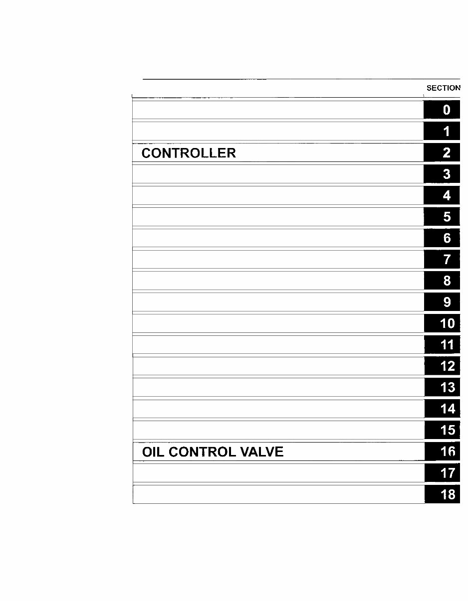
SECTION INDEX NAME 1 SECTION GENERAL BATTERY y MULTI-DISPLAY FUNCTIONS TROUBLESHOOTING MOTOR DRIVE UNIT FRONT AXLE REAR AXLE STEERING BRAKE BODY MATERIAL HANDLING SYSTEM MAST CYLINDER OIL PUMP p 8 SAS FUNCTIONS / APPENDIX
GENERAL Page Page EXTERIOR VIEWS ........................... 0-2 RECOMMENDED LUBRICANT .................. VEHICLE MODEL 0-3 QUANTITY & TYPES 0-18 rn ............................. ................. FRAME NUMBER ............................. 0-4 LUBRICATION CHART 0-19 ......... HOW TO USE THIS MANUAL ...... 0-5 PERIODIC MAINTENANCE 0-21 EXPLANATION METHOD ................ 0-5 PERIODIC REPLACEMENT OF ...... TERMINOLOGY 0-6 PARTS AND LUBRICANTS 0-26 ................................. ABBREVIATIONS .............................. 0-6 OPERATIONAL TIPS ...................... 0-7 JACK-UP POINT .............................. 0-8 .............. HOISTING THE VEHICLE 0-9 CAUTION FOR TOWING ................ 0-9 ATTENTIVE POINTS ON SAS .... 0-10 CIRCUIT TESTER .......................... 0-11 STANDARD BOLT & NUT TIGHTENING TORQUE .............. 0-13 BOLT STRENGTH TYPE .......... IDENTIFICATION METHOD 0-13 ...... TIGHTENING TORQUE TABLE 0-14 PRECOAT BOLTS .......................... 0-15 HIGH PRESSURE HOSE FITTING TIGHTENING TORQUE ......................................... 0-15 WlRE ROPE SUSPENSION ANGLE LIST .................................. 0-16 SAFE LOAD FOR EACH WlRE ROPE SUSPENSION ANGLE ............................................ 0-16 COMPONENTS WEIGHT ............. 0-17
FRAME NUMBER Frame No. Punching Position Punching position *: EEC spec. Punching format 7FBCU45-60011 307FBCU45-60011 7FBCU55-60011 307FBCU55-60011 Vehicle Model 7FBCu35 7FBCU45 30-7FBCU35 30-7FBCU45 7FBCU55 30-7FBCU55 Vehicle Model 7FBCU15 7FBCU18 30-7FBCU 15 30-7FBCU 18 7FBCU20 7FBCU25 Punching format 7FBCU18-60011 * 7FBCU18@60011 307FBCU18-60011 * 307FBCU18@60011 7FBCU25-60011 * 7FBCU25@60011 30-7FBCU20 30-7FBCU25 7FBCHU25 30-7FBCHU25 7FBCU30 7FBCU32 30-7FBCU30 30-7FBCU32 307FBCU25-60011 * 307FBCU25@60011 7FBCHU25-60011 307FBCHU25-60011 7FBCU32-60011 * 7FBCU32@60011 307FBCU32-60011 * 307FBCU32@60011
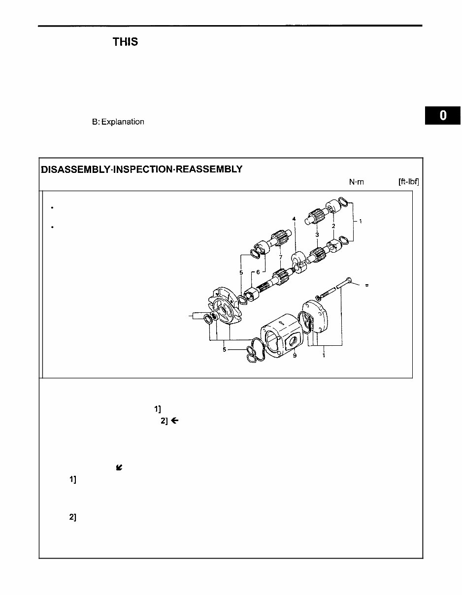
HOW TO USE THIS MANUAL EXPLANATION METHOD 1. Operation procedure (1) The operation procedure is described in either pattern A or pattern B below. Pattern A: Explanation of each operation step with illustration. Pattern B:Explanation of operation procedure by indicating step numbers in one illustration, followed by explanation of cautions and notes summarized as point operations. Example of description in pattern B DISASSEMBLY.INSPECTI0N.REASSEMBLY Tightening torque unit T = N-m(kgf-cm) [ft-lbfl Step Nos. are partially sometimes omitted in illustrations. When a part requiring tightening torque instruction is not indicated in the illustration, the part name is described in the illustration frame. T = 46.1 - 48.1 (470 - 490) (34.0 - 35.51 8 Disassembly Procedure 1 Remove the cover. [Point I] 2 Remove the bushing [Point 21 C Operation explained later 3 Remove the gear. Point Operations Explanation of key point for operation with an illustration Y [Point I] Disassembly: Put a match mark when removing the pump cover. [Point 21 Inspection: Measure the bushing inside diameter. Limit: 19.12 mm (0.7528 in)
This is a comprehensive Service Repair Manual for the TOYOTA ELECTRIC POWERED FORKLIFT 7FBCU15-55 & 7FBCHU25. It contains in-depth information about maintenance, assembly, disassembly, and servicing of the mentioned models.
Models Covers:
7FBCU15
7FBCU18
7FBCU20
7FBCU25
7FBCHU25
7FBCU30
7FBCU32
7FBCU35
7FBCU45
7FBCU55
Table of Contents:
General
Battery
Controller
Multi-display functions
Troubleshooting
Motor
Drive unit
Front axle
Rear axle
Steering
Brake
Body
Material handling system
Mast
Cylinder
Oil pump
Oil control valve
Sas functions
Appendix
Model Specification: TOYOTA ELECTRIC POWERED FORKLIFT 7FBCU15-55 & 7FBCHU25
Language: English
Total Pages: 915
File Format: .PDF
Requirements: Adobe Reader
ZOOM IN/OUT: YES
Printable: YES
Compatible: All Versions of Windows & Mac
This manual contains information, data, specs, diagrams, actual real photo illustrations, and schemes. It is a valuable resource for diagnosing, repairing, and maintaining TOYOTA machinery. The manuals are compatible with various Windows and Mac operating systems.
Tons of pictures and diagrams are included, making it easy for users at any skill level to follow the step-by-step instructions. All pages are printable, allowing for easy access in the garage or workshop, ultimately saving money by enabling DIY repairs.
Recently Viewed
5,521,897Happy Clients
2,594,462eManuals
1,120,453Trusted Sellers
15Years in Business
Price:
Actual Price:
TOYOTA Electric POWERED Forklift 7FBCU15-55 & 7FBCHU25 Service Repair Manual