

Toyota 6FGCU15/6FGCU18/6FGCU20/6FGCU25/6FGCU30 LPG Forklift Service & Repair Manual
What's Included?
Fast Download Speeds
Offline Viewing
Access Contents & Bookmarks
Full Search Facility
Print one or all pages of your manual

FOREWORD
This manual covers the service procedures of the TOYOTA FORKLIFT
6FGCU 15 - 30. Please use this manual for providing quick, correct ser-
vicing of the corresponding forklift models.
This manual deals with the above models as of July 1995. Please
understand that disagreement can take place between the descriptions
in the manual and actual vehicles due to change in design and specifica-
tions. Any change or modifications thereafter will be informed by
Toyota Industrial Equipment Parts & Service News.
For the service procedures of the mounted engine, read the repair
manuals listed below as reference together with this manual.
(Reference)
Repair manuals related to this manual are as follows:
TOYOTA INDUSTRIAL EQUIPMENT 4Y ENGINE
REPAIR MANUAL (No. CE602)
TOYOTA INDUSTRIAL EQUIPMENT GM4 - 181 ENGINE
REPAIR MANUAL (No. CU629)
TOYOTA MOTOR CORPORATION
SECTION INDEX
GENERAL
ENGINE
NAME
TORQUE CONVERTER
DIFFERENTIAL
FRONT AXLE
REAR AXLE
STEERING
BRAKE
BODY
MATERIAL HANDLING SYSTEM
MAST
CYLINDER
OIL PUMP
OIL CONTROL VALVE
APPENDIX
SECTION
GENERAL
Page
EXTERIOR VIEWS ............................................... 0-2
VEHICLE MODEL ................................................ 0-3
FRAME NUMBER .............................................. 0-4
.......................... HOW TO READ THIS MANUAL 0-5
EXPLANATION METHOD ....................................... 0-5
TERMINOLOGY ................................................... 0-6
ABBREVIATIONS .................................................. 0-6
OPERATIONAL TIPS ............................................ 0-7
STANDARD BOLT & NUT TIGHTENING
TORQUE ........................................................... 0-8
BOLT STRENGTH TYPE IDENTIFICATION
.......................................................... METHOD 0-8
................................ TIGHTENING TORQUE TABLE 0-9
PRECOAT BOLTS .............................................. 0-10
HIGH PRESSURE HOSE FITTING
..................................... TIGHTENING TORQUE 0-10
WIRE ROPE SUSPENSION ANGLE LIST ............. 0-11
SAFE LOAD FOR EACH WlRE ROPE
SUSPENSION ANGLE ....................................... 0-11
COMPONENTS WEIGHT ..................................... 0-12
RECOMMENDED LUBRICANT
........................................ QUANTITY & TYPES 0-13
........................................ LUBRICATION CHART 0-14
.................................. PERIODIC MAINTENANCE 0-15
PERIODIC REPLACEMENT OF PARTS
AND LUBRICANTS ........................................... 0-21
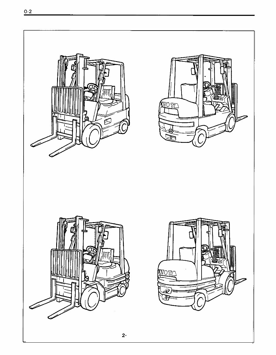
EXTERIOR VIEWS
1 ton series
2- 3 ton series
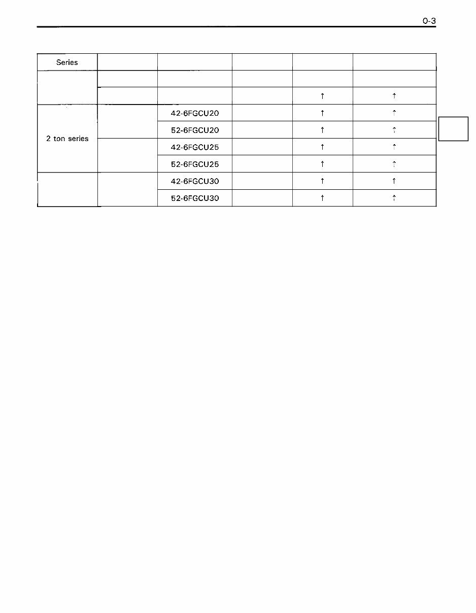
VEHICLE MODEL
Series
+
1 ton series
2 ton series
L
3 ton series
1.5 ton
1.75 ton
Engine type Engine model Load capacity
2.0 ton
Drive system Model
42- 6FGCU 1 5
42- 6FGCU1 8
2.5 ton
3.0 ton
42-6FGCU20
52-6FGCU20
4Y
4Y
42-6FGCU25
52-6FGCU25
42-6FGCU30
52-6FGCU30
4Y
GM
Gasoline
t
4Y
GM
4Y
GM
Torque converter
'I
t
t
t
t
t
t
t
t
t
t
T
t
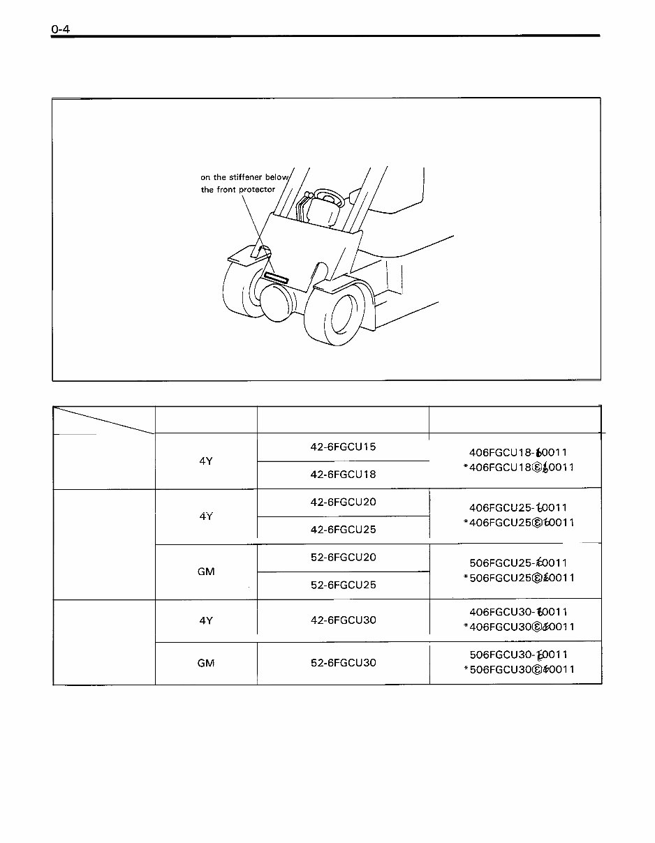
FRAME NUMBER
Frame No. Punching Position
Punching position
1 ton series
2 ton series
I I
Punching format Engine
3 ton series
I I
Model
*: EEC Spec.
HOW TO READ THIS MANUAL
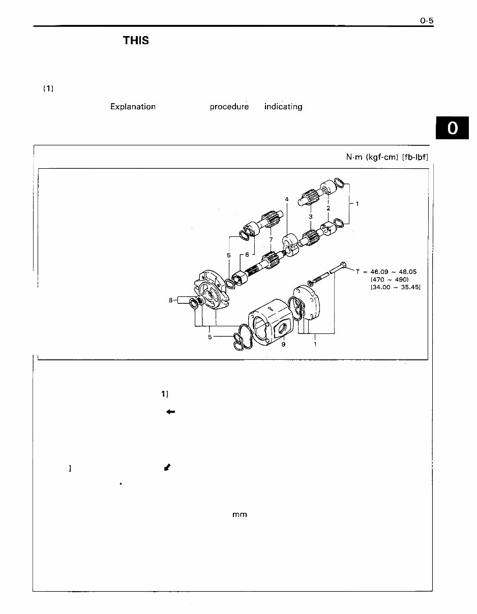
EXPLANATION METHOD
1. Operation procedure
(1) The operation procedure is described in either pattern A or pattern B below.
Pattern A: Explanation of each operation step with a photo or illustration.
Pattern B: ~xplanation of operation procedure by indic-sting step numbers in one illustration,
followed by explanation of cautions and notes summarized as point operations.
Example of description in pattern B
/ DISASSEMBLY. INSPECTION. REASSEMBLY Tightening torque unit T = Nm (kgf-cm) [fb-lbfl
If a place or part cannot be indicated
directly, the part name is described on
the either side of the illustration.
Example: 1 Piping
Disassembly Procedure
1 Remove the cover. [Point 11
2 Remove the bush [Point 21 4- Operation explained later
3 Remove the gear.
1 Point operations Explanation of key point for operation with an illustration
[Point 1 I &
Disassembly: Put a match mark when removing the pump cover.
6
[Point 21
Inspection: Measure the bush inside diameter.
Bush inside diameter limit: 19.1 2 mm (0.7528 in)
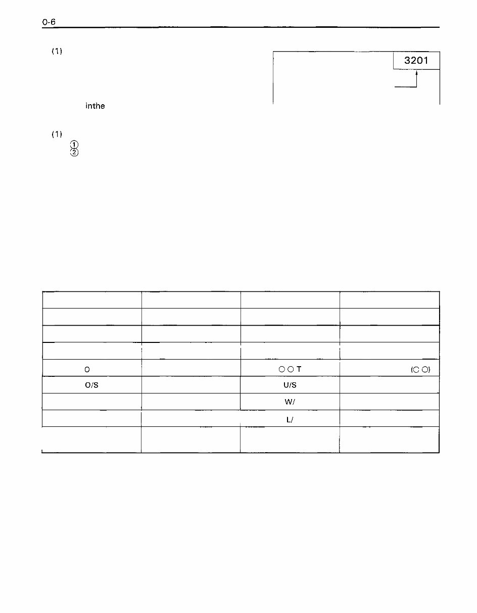
2. How to read components figures (Example)
(1 ) The components figure uses the illustration
in the parts catalog for the vehicle model.
Please refer to the catalog for checking the
part name.
The number at the right shoulder of each FIG number in parts catalog
components figure indicates the Fig. num-
ber inthe parts catalog.
3. Matters omitted in this manual
(1) This manual omits description of the following jobs, but perform them in actual operation:
@
Cleaning and washing of removed parts as required
@ Visual inspection (partially described)
TERMINOLOGY
Caution:
lmportant matters of which negligence may cause accidents. Be sure to abserve them.
Note:
Important items of which negligence may cause accidents, or matters in operation procedure re-
quiring special attention.
Standard: Values showing allowable range in inspection and adjustment.
Limit: Maximum or minimum allowable value in inspection or adjustment.
ABBREVIATIONS
I LH 1 Left hand I STD I Standard
Abbreviation (code)
ASSY
I LLC I Long life coolant I T = I Tightening torque
I 0 PT 1 Option I OOT I Number of teeth (0 0)
Meaning
Assembly
I RH 1 Right hand 1 L/ I Less
Abbreviation (code)
SST
01s
PS
SAE
Meaning
Special service tool
Society of Automotive
Engineers (USA)
Oversize
Power steering
U/S
W/
Undersize
With
OPERATIONAL TIPS
1. Safe operation
(1) After jacking up, always support with rigid stands.
(2) When hoisting the vehicle or its heavy component, use wire repe(s) with a sufficient reserve in
load capacity.
(3) Always disconnect the battery plugs before the inspection or servicing of electrical parts.
2. Tactful operation
Prepare the mechanic tools, necessary measuring instruments (circuit tester, megger, oil pres-
sure gauge, etc.) and SSTs before starting operation.
Before disconnecting wiring, always check the cable color and wiring state.
When overhauling functional parts, complicated portions or related mechanisms, arrange the parts
neatly to prevent confusion.
When disassembling and inspecting such a precision part as the control valve, use clean tools
and operate in a clean location.
Follow the described procedures for disassembly, inspection and reassembly.
Replace, gaskets, packings and O-rings with new ones each time they are disassembled.
Use genuine Toyota parts for replacement.
Use specified bolts and nuts. Observe the specified tightening torque at the time of reassembly.
If no tightening torque is specified, tighten the bolt or nut according to the standard tightening
torque table.
3. Grasping the trouble state
When a trouble occurs, do not attempt immediate disassembly or replacement but first check if
the trouble requires disassembly or replacement for remedying.
STANDARD BOLT & NUT TIGHTENING TORQUE
Standard bolt and tightening torques are not indicated.
Judge the standard tightening torque as shown below.
1. Find out the type of the bolt from the list below and then find the bolt tightening torque from the table.
2. The nut tightening torque can be judged from the mating bolt type.
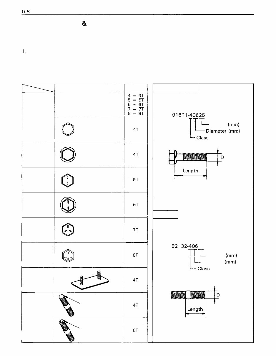
BOLT STRENGTH TYPE IDENTIFICATION METHOD
1. lndentification by bolt shape 2. Identification by part No.
Hexagon head bolt Shape and class Class
@ -
Bolt head No.
Parts No.
9161 1-40625
1T-L Length (rnm)
Hexagon
head bolt
0
No mark
No mark
iarneter
Hexagon
flange bolt
Length
H
Two protruding
lines
Hexagon
head bolt
Two protruding
lines
Hexagon
flange bolt
Stud bolt /
Three protruding
lines
Hexagon
head bolt
Part No.
921 32-40614
Length (rnm)
Diameter (mm)
Four protruding
@ lines
Hexagon
head bolt
Welded bolt
iarneter
$-
No mark
Stud bolt
Grooved
You're Reading a Preview
What's Included?
Fast Download Speeds
Offline Viewing
Access Contents & Bookmarks
Full Search Facility
Print one or all pages of your manual
$37.99
Viewed 69 Times Today


Secure transaction
What's Included?
Fast Download Speeds
Offline Viewing
Access Contents & Bookmarks
Full Search Facility
Print one or all pages of your manual
$37.99
Toyota 6FGCU15/6FGCU18/6FGCU20/6FGCU25/6FGCU30 LPG Forklift Service & Repair Manual – an essential resource featuring high-quality images, detailed circuit diagrams, and clear instructions for the operation, maintenance, and repair of your forklift truck. This manual is designed for ease of use with printable pages, searchable text, and navigation bookmarks.
Covered models:
- 42-6FGCU15
- 42-6FGCU18
- 42-6FGCU20
- 42-6FGCU25
- 42-6FGCU30
- 52-6FGCU20
- 52-6FGCU25
- 52-6FGCU30
Language: English
Contained Set of Manuals:
- Main Service Manual, 331 Pages
- GENERAL
- ENGINE
- TORQUE CONVERTER
- DIFFERENTIAL
- FRONT AXLE
- REAR AXLE
- STEERING
- BRAKE
- BODY
- MATERIAL HANDLING SYSTEM
- MAST
- CYLINDER
- OIL PUMP
- OIL CONTROL VALVE
- APPENDIX
- Wiring Diagram, 1 page


