Toyota 52-6FGU45 Forklift Factory Service & Work Shop Manual
What's Included?
Lifetime Access
Fast Download Speeds
Online & Offline Access
Access PDF Contents & Bookmarks
Full Search Facility
Print one or all pages of your manual
FOREWORD This manual covers the service procedures of the TOYOTA FORKLIFT 6FGU16FDU33-45, 6FGAU16FDAU50. Please use this manual for providing quick, correct servicing of the corresponding forklift models. This manual deals with the above models as of March 1997. Please understand that disagreement can take place between the descriptions in the manual and actual vehicles due to change in design and specifications. Any change or modifications thereafter will be informed by Toyota Industrial Equipment Parts & Service News. For the service procedures of the mounted engine, read the repair manuals listed below as reference together with this manual. (Reference) Repair manuals related to this manual are as follows: TOYOTA INDUSTRIAL EQUIPMENT GM6-262 ENGINE REPAIR MANUAL (No. C4630) TOYOTA INDUSTRIAL EQUIPMENT 11Z,12Z,13Z,14Z ENGINE REPAIR MANUAL (No. C4615) TOYOTA MOTOR CORPORATION
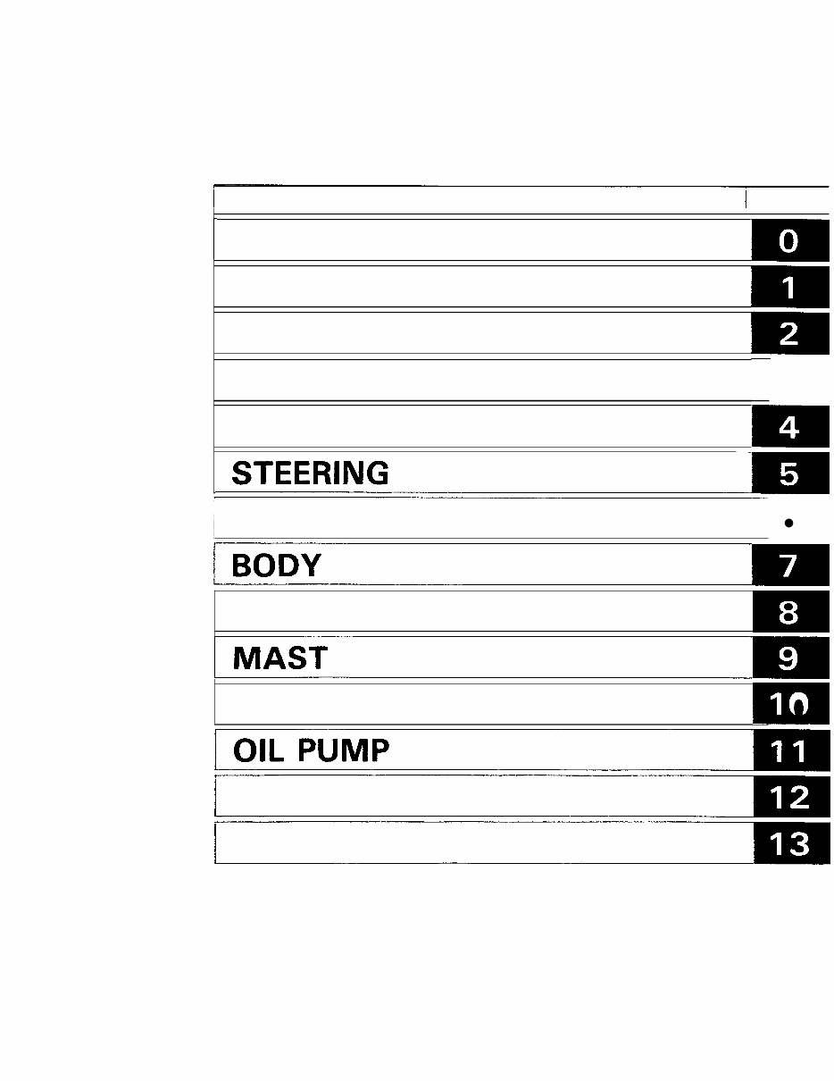
SECTION INDEX I NAME 1 SECTION I I GENERAL ENGINE TORQUE CONVERTER FRONT AXLE REAR AXLE STEERlNG rn BRAKE MATERIAL HANDLING SYSTEM 0 0 MAST CYLINDER o OIL CONTROL VALVE APPENDIX
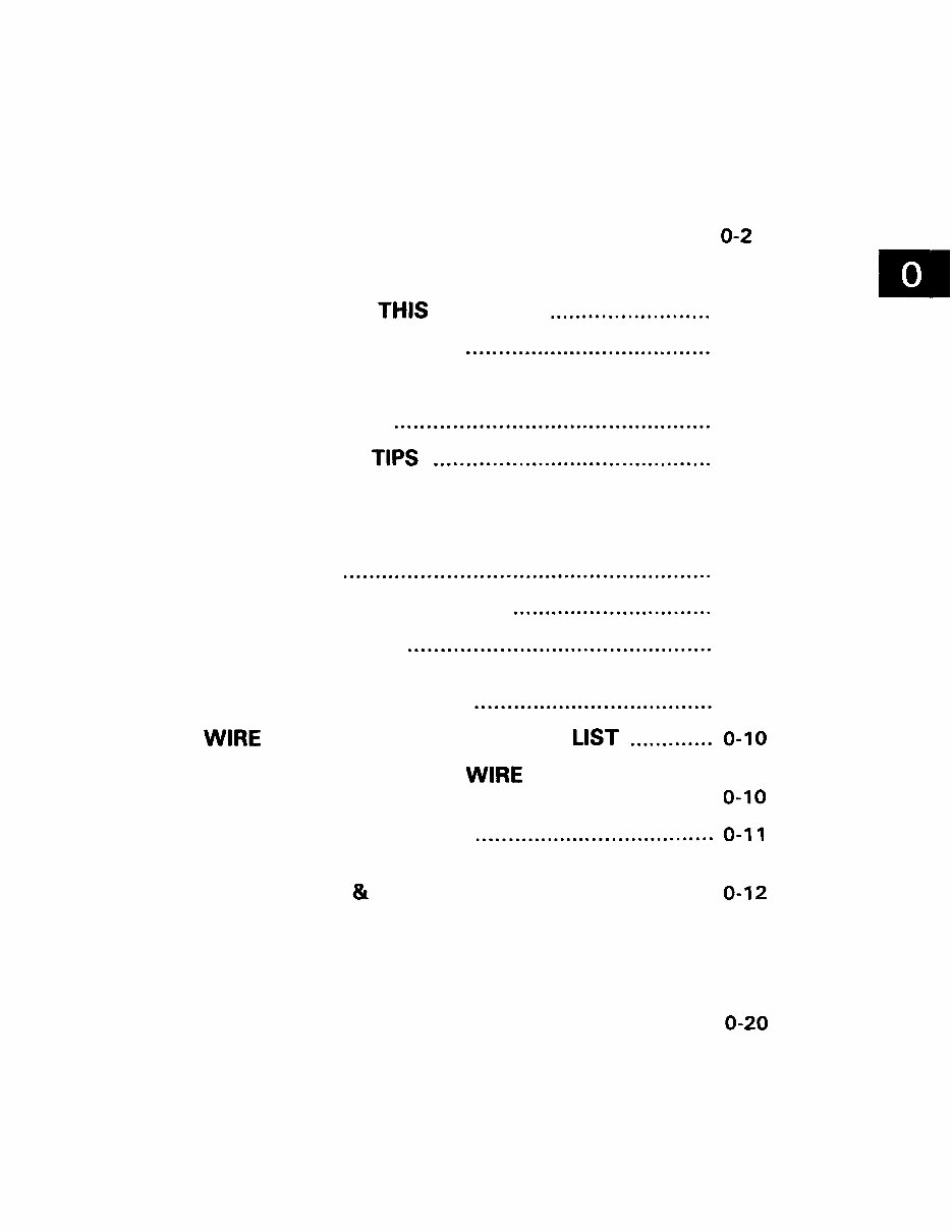
GENERAL Page ............................................... EXTERIOR VIEWS 0-2 ................... VEHICLE MODEL-FRAME NUMBER 0-3 HOW TO READ THIS MANUAL ......................... 0-4 EXPLANATION METHOD ...................................... 0-4 ................................................... TERMINOLOGY 0 -5 ABBREVIATIONS ................................................. 0 -5 OPERATIONAL TIPS ........................................... 0 -6 STANDARD BOLT AND NUT TIGHTENING ........................................................... TORQUE 0 -7 BOLT STRENGTH TYPE IDENTIFICATION METHOD ........................................................ 0 -7 TIGHTENING TORQUE TABLE ............................... 0-8 PRECOAT BOLTS ............................................... 0 -9 HIGH PRESSURE HOSE FITTING TIGHTENING TORQUE ..................................... 0 -9 WIRE ROPE SUSPENSION ANGLE LIST ............. 0-10 SAFE LOAD FOR EACH WlRE ROPE ....................................... SUSPENSION ANGLE 0-10 COMPONENTS WEIGHT ..................................... 0-11 RECOMMENDED LUBRICANT ....................................... QUANTITY & TYPES 0-12 ........................................ LUBRICATION CHART 0 -13 .................................. PERIODIC MAINTENANCE 0-14 PERIODIC REPLACEMENT OF PARTS ........................................... AND LUBRICANTS 0-20
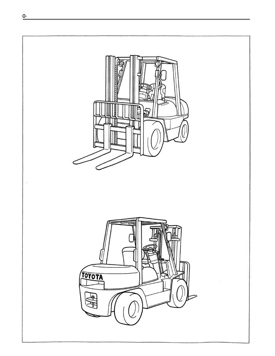
0- 2 EXTERIOR VIEWS
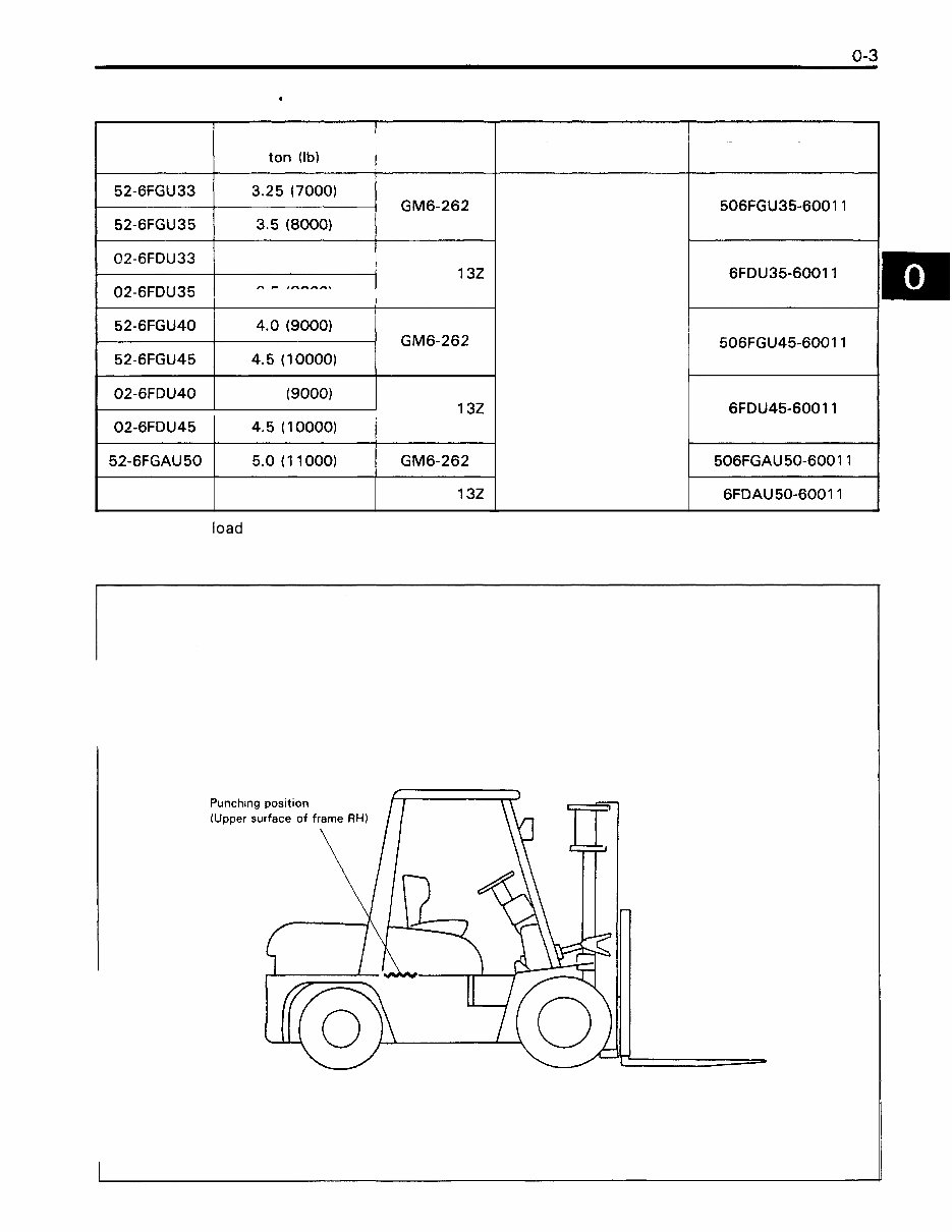
VEHICLE MODEL * FRAME NUMBER Model Load capacity * Engine 02-6FDU33 3.25 (7000) TOYOTA 132 02-6FDU35 3.5 (8000) *: When the load center is 600 mm (24 in) TOYOTA 132 -- - 02-6FDU40 02-6FDAU 50 Drive system Punching format -- 4.0 (9000) Torque converter I 506FGU45-60011 5.0 (11000) Frame No. punching position TOYOTA 132
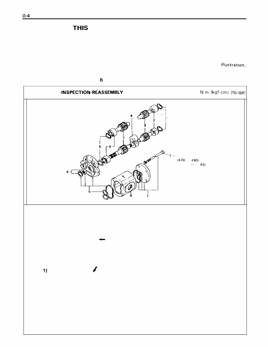
HOW TO READ THIS MANUAL EXPLANATION METHOD 1. Operation procedure (1) The operation procedure is described in either pattern A or pattern B below. Pattern A: Explanation of each operation step with an illustration. Pattern B: Explanation of operation procedure by indicating step numbers in one illustration, followed by explanation of cautions and notes summarized as point operations. Example of description in pattern I3 DISASSEMBLY .INSPECTION.REASSEMBLY Tightening torque unit T = N.m (kgf-cm) [fb-lbf] 1 'T = 46.09 - 48.05 (470 - 4901 134.00 -- 35 451 8 Disassembly Procedure 1 Remove the cover. [Point 11 2 Remove the bush [Point 21 - Operation explained later 3 Remove the gear. Point operations Explanation of key point for operation with an illustration [Point 11 1 Disassembly: Put a match mark when removing the pump cover. [Point 21 Inspection: Measure the bush inside diameter. Bush inside diameter limit: 19.12 mm (0.7528 in)
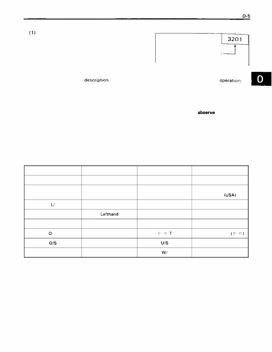
2. H o w to read components figures (Example) (1 1 The components figure uses the illustra- tion in the parts catalog for the vehicle model. Please refer to the catalog for checking the part name. The number at the right shoulder of each FIG number in parts catalog components figure indicates the Fig. num- ber in the parts catalog. 3. Matters omitted in this manual (1) This manual omits descript~on of the following jobs, but perform them in actual operation: Cleaning and washing of removed parts as required 2 Visual inspection (partially described) 8 TERMINOLOGY Caution: Important matters of which negligence may cause accidents. Be sure to abserve them. Note: Important items of which negligence may cause accidents, or matters in operation procedure re- quiring special attention. Standard: Values showing allowable range in inspection and adjustment. Limit: Maximum or minimum allowable value in inspection or adjustment. ABBREVIATIONS Abbreviation (code) ASSY FHPS L/ LH LLC 0 PT 01s PS Meaning Assembly Full hydraulic power steering Less Lefthand Long life coolant Option Oversize Power steering Abbreviation (code) RH SAE SST STD T = OT U/S W/ Meaning Righthand Society of Automotive Engineers (USA) Special service tool Standard Tightening torque Number of teeth (0 0 ) Undersize With
OPERATIONAL TIPS 1. Safe operation (1) After jacking up, always support with rigid stands. (2) When hoisting the vehicle or its heavy component, use wire rope(s) with a sufficient reserve in load capacity. (3) Always disconnect the battery plugs before the inspection or servicing of electrical parts. 2. Tactful operation (1) Prepare the mechanic tools, necessary measuring instruments (circuit tester, megger, oil pres- sure gauge, etc.) and SSTs before starting operation. (2) Before disconnecting wiring, always check the cable color and wiring state. (3) When overhauling functional parts, complicated portions or related mechanisms, arrange the dis- assembled parts neatly to prevent confusion. (4) When disassembling and inspecting such a precision part as the control valve, use clean tools and operate in a clean location. (5) Follow the described procedures for disassembly, inspection and reassembly. (6) Replace gaskets, packings and O-rings with new ones each time they are disassembled. (7) Use genuine Toyota parts for replacement. (8) Use specified bolts and nuts. Observe the specified tightening torque at the time of reassembly. If no tightening torque is specified, tighten the bolt or nut according to the standard tightening torque table. 3. Grasping the trouble state When a trouble occurs, do not attempt immediate disassembly or replacement but first check if the trouble requires disassembly or replacement for correction.
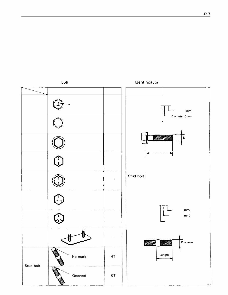
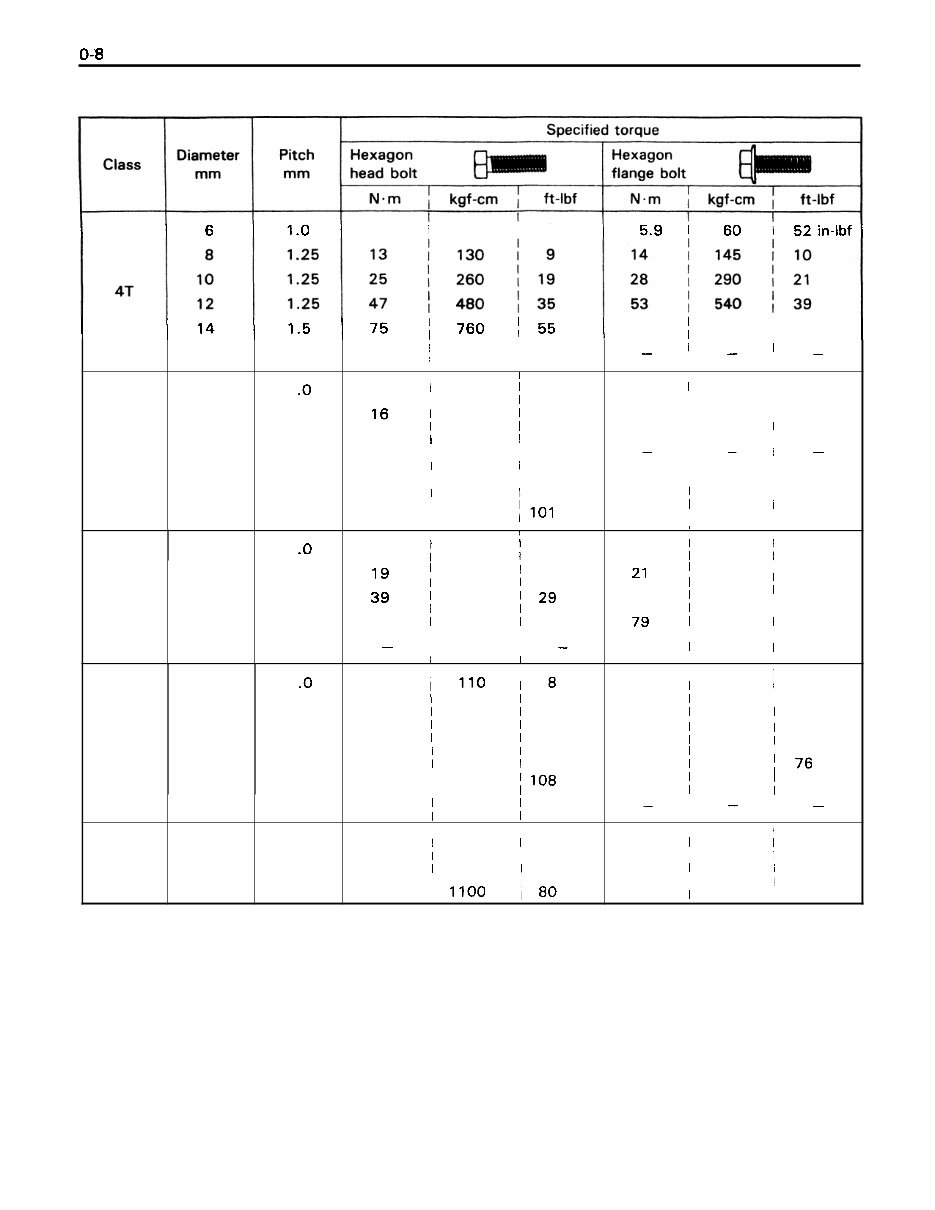
STANDARD BOLT AND NUT TIGHTENING TORQUE How to judge tightening torque of a standard bolt or nut 1. How to judge tightening torque of a standard bolt: Find out the type of the bolt from the list below. Then, find the bolt tightening torque from the table. 2. How to judge tightening torque of a standard nut: The nut tightening torque can be judged from the bolt type. (See the item above.) BOLT STRENGTH TYPE IDENTIFICATION METHOD 1. Identification by bolt shape 2. Identification by part No. Hexagon Two protruding head bolt lines 5T Class 4 = 4T 5 = 5T 6 = 6T 7 = 7T 8 = 8T 4T Shape and class Hexagon flange bolt Hexagon Two protruding flange bolt lines 6T Hexagon head bolt Hexagon Three protruding head bolt lines 7T @ Bolt head No. No mark No mark Hexagon Four protruding head bolt lines 8T 4T Welded bolt 4T I Hexagon head bolt Part No. 9161 1-40625 1T-L Length (mm) I Diameter (mm) L Class iameter I Length I Stud bolt r Part No. 92 132-406 14 [TL Length (mm) I Diameter lmml L Class
TIGHTENING TORQUE TABLE 5.4 I 55 I 48 in-lbf 5T 6T 7T 8T 16 6 8 10 12 14 16 6 8 10 12 14 6 8 10 12 14 16 8 10 12 1.5 1 .O 1.25 1.25 1.25 1.5 1.5 1 .O 1.25 1.25 1.25 1.5 1 .o 1.25 1.25 1.25 1.5 1.5 1.25 1.25 1.25 113 / 1150 83 I I 6.4 1 65 1 56 in-lbf I 1 160 1 12 I 3 2 I 330 I 24 I I 5 9 1 600 I 43 I I 9 1 1 930 1 67 137 11400 1101 I I 7.8 1 80 1 69 in-lbf I 195 14 l9 I 1 400 129 39 1 7 2 1 730 1 53 I - I I I - I I 11 I I 1110 1 8 25 1 260 1 19 52 1 530 1 38 95 1 970 1 70 147 1500 1108 226 1 2300 1 166 I I I 29 I 300 I 22 1 I 6 1 1 620 I 45 110 I I 11100 180 83 j 850 61 - I _ I _ I I I I 1 I I I I I I I I I - I - I - I I I I I I I I I I I I 8.8 1 90 1 78 in-lbf I 215 1 16 21 I 43 440 3 2 I 1 810 1 59 79 1 I 123 I 1250 I 90 I I I I 12 1 120 1 9 I I 28 1 290 1 21 58 1 590 1 43 103 / 1050 176 167 1 1700 1 123 - I - I - I I I I 3 3 I 330 I 24 I I 68 I 690 I 50 I I 120 1 1250 1 90
Upon purchasing this manual, you will receive a .PDF file containing an email contact. After contacting us, you will receive a reply with a link to access the manual for your Toyota 52-6FGU45 Forklift.
This comprehensive manual covers every aspect of your machine, providing detailed guidance on every nut and bolt. With hundreds of pages, it offers instructions on diagnosing and fixing various issues, from simple tasks like an oil change to more complex procedures like a transmission swap. The manual includes numerous illustrations to assist you and features easy-to-understand text throughout.
Utilize the search function to navigate the manual efficiently and print the necessary pages as needed. This Factory Service Repair Manual is designed to walk you through the fundamentals of maintenance and repair, providing step-by-step instructions to equip you with the knowledge that factory-trained technicians possess. By utilizing the insights in this service repair manual, any owner can confidently make informed decisions regarding the maintenance and repair of their machine.
Rest assured, in addition to the high-quality service manual, we are committed to delivering excellent customer service, ensuring your satisfaction with your purchase.
Recently Viewed
5,521,897Happy Clients
2,594,462eManuals
1,120,453Trusted Sellers
15Years in Business
Price:
Actual Price:
Toyota 52-6FGU45 Forklift Factory Service & Work Shop Manual