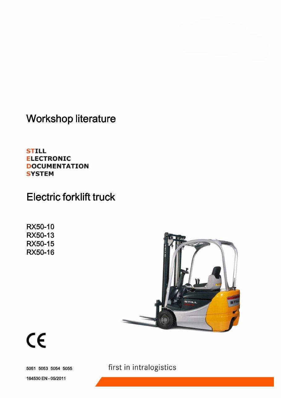
Workshop literature STILL ELECTRONIC DOCUMENTATION SYSTEM Electric forklift truck RX50-10 RX50-13 RX50-15 RX50-16 5051 5053 5054 5055 164530 EN -05/2011 first in intralogistics
History of changes r Edition 05/201 1 Edition 03/2005 • Version 5 • Version 3 • Update of the entire book and standardization • Completely revised edition of the RX-series workshop manuals • Generation 5 converter added Edition 08/2005 • Version 4 • Servo hydraulics has been added 164530 [EN]
Header r Documentation This workshop manual contains all the informa¬ tion required to assist the trained service engi¬ neers with all work, repairs and maintenance on this truck. In addition, some of the compo¬ nents have been deliberately excluded from this workshop manual and are explained elsewhere in order to ensure a clear overview. Changes at short notice are possible at anytime and are com¬ municated via Service Information documents. The additional documentation comprises work¬ shop manuals, special documentation and oper¬ ating circuit diagrams. Workshop manuals • Display elements -display • FleetManager™ Special documentation • Error list • Overview of truck software • STILL Flasher • Overview of consumables • FEM 4.004 test log book Operating circuit diagrams • see the circuit diagram overview Symbols Used The signal terms Danger, Warning, Caution, Note and Environment note are used in this document as hazard warnings or for unusual information that requires special identification: A DANGER means that failure to comply involves risk to life and/or major damage to property can occur. A WARNING means that failure to comply involves risk of serious injury and/or major damage to property can occur. A CAUTION means that failure to comply involves risk of material damage or destruction. 164530 [EN] III
1 Header (D NOTE means that particular attention is drawn to com¬ binations of technical factors which may not be evident even to a specialist. The instructions listedhere must be complied with as otherwise environmental damage may result. For your safety, additional symbols are also used. Please heed the various symbols. Changes and retrofitting Warnings before making changes to the truck If the truck is used for work not listed in the guidelines or truck-specific original operating instructions and has to be converted or retrofitted accordingly, you should be aware of the following: • Any structural modification can affect the handling and stability of the truck, and can result in accidents. • Without authorisation from STILL, no changes that affect the stability, the load capacity and the safety systems may be carried out. • Operation of the truck without an overhead guard at a lift height of over 1800 mm is prohibited. • It is prohibited to install and use restraint systems that are not approved by STILL. • It is prohibited to drill holes in the overhead guard or to perform welding on it. • When carrying out welding on other parts of the truck, it is essential that the battery and all connections to the electronic controls are disconnected. • Only for electric forklift trucks: It is prohibited to drill holes in the area of the driver's seat into the battery hood because hydrogen can enter through the bores into the driver's cab. ENVIRONMENT NOTE IV 164530 [EN]
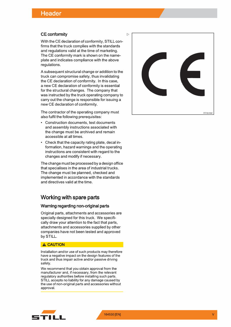
Header r CE conformity > With the CE declaration of conformity, STILL con¬ firms that the truck complies with the standards and regulations valid at the time of marketing. The CE conformity mark is shown on the name- plate and indicates compliance with the above regulations. A subsequent structural change or addition to the truck can compromise safety, thus invalidating the CE declaration of conformity. In this case, a new CE declaration of conformity is essential for the structural changes. The company that was instructed by the truck operating company to carry out the change is responsible for issuing a new CE declaration of conformity. The contractor of the operating company must also fulfil the following prerequisites: • Construction documents, test documents and assembly instructions associated with the change must be archived and remain accessible at all times. • Check that the capacity rating plate, decal in¬ formation, hazard warnings and the operating instructions are consistent with regard to the changes and modify if necessary. The change must be processed by a design office that specialises in the area of industrial trucks. The change must be planned, checked and implemented in accordance with the standards and directives valid at the time. CE-Symbol Working with spare parts Warning regarding non-original parts Original parts, attachments and accessories are specially designed for this truck. We specifi¬ cally draw your attention to the fact that parts, attachments and accessories supplied by other companies have not been tested and approved by STILL. A CAUTION Installation and/or use of such products may therefore have a negative impact on the design features of the truck and thus impair active and/or passive driving safety. We recommend that you obtain approval from the manufacturer and, if necessary, from the relevant regulatory authorities before installing such parts. STILL accepts no liability for any damage caused by the use of non-original parts and accessories without approval. 164530 [EN] V
1 Header Working with electronic controls It is not generally permitted to open controls. STILL's liability and the warranty are no longer applicable once the seal has been damaged. In exceptional cases, personnel authorised by STILL are allowed to open the controls. VI 164530 [EN]
r 00 Product information Safety instructions oo- 1 Safety instructions Electrical system 00- 1 Jacking up the front of the truck 00- 1 Jacking up the rear of the truck 00- 2 Securing the fork carriage 00- 3 11 Electrical motor Motor 11- 1 General technical data 11- 1 Electrical connections 11- 2 Drive unit 11- 3 Traction motor rotor disassembly 11- 4 Traction motor rotor assembly 11- 5 Speed sensor 11- 7 6B17 pin sensor 11- 7 6B17 sensor bearing 11- 8 Removing the sensor bearing 11-10 Installing the sensor bearing 11-11 Temperature sensor 11-13 KTY84 temperature sensor 11-13 Forced ventilation 11-15 Forced ventilation at the pump motor Heavy dust guard 11-15 22 Mechanical drive axle Wheel drive 22- 1 Wheel hub removal 22- 1 Installing the wheel hub 22- 2 Power unit 22- 4 General technical data 22- 4 power unit 22- 5 Power unit disassembly 22- 5 Power unit installation 22- 7 31 Chassis Counterweight 31- 1 Counterweight 31- 1 164530 [EN] VII
1 34 Driver's compartment Driver's seat 34- 1 seat contact switch 34- 1 Seatbelt lock switch 34- 1 42 Steering system Hydraulic steering 42- 1 General technical data 42- 1 steering system 42- 2 Steering — error detection 42- 3 Steering motor 42- 3 steering motor removal 42- 4 Steering motor installation 42- 5 Sprocket with trigger wheel 42- 6 Steering unit 42- 8 diaphragm pressure switch 42- 9 Priority valve 42-10 Steering-angle-dependent performance - CSC 42- 11 CSC — functional test 42-12 3B28 steering zero sensor 42-13 Steering angle sensor with sensor disc 42-14 Steering angle sensor 42-15 Steering wheel with steering column 42- 17 steering column 42-17 46 Wheels and tires Complete wheel assembly 46- 1 General technical data 46- 1 Superelastic tyres 46- 1 Wheel bearing 46- 3 General technical data 46- 3 Wheel bearing — wheel hub 46- 3 49 Brake system Hydraulic service brake 49- 1 General technical data 49- 1 Replacing the brake shoes 49- 1 Checking the service brake 49- 4 VIII 164530 [EN]
Table of contents r Wheel brake cylinder 49- 5 Main brake cylinder 49- 6 Brake sensor 1B2 49- 7 Brake fluid switch 49- 8 Parking brake 49- 9 Adjusting the parking brake 49- 9 parking brake switch 49- 11 50 Operational controls Single pedal 50- 1 Single-pedal accelerator 50- 1 Twin-pedal 50- 5 Two-pedal accelerator 50- 5 Operational controls 50- 8 Hand lever 50- 8 joystick 50- 9 Joystick operation 50-11 Fingertip 50-12 Axle assignment 50-14 Depressurising the hydraulics 50-17 Switch 50-18 emergency isolator switch 50-18 Emergency off switch in the joystick 50- 18 Key switch 50-19 56 Indicator elements operator control panel 56- 1 keypad 56- 1 mini console 56- 3 Display 56-7 Display and operating element -control processor 56- 7 Programming mode 56- 9 Password level 1 56- 11 Password level 2 56- 15 164530 [EN] IX
1 60 Electrical system / electronic system General 60- 1 General technical data 60- 1 Device code and read options 60- 2 Overview of electrical components 60- 3 Electrical system 60- 4 Switching on procedure for the electrical system 60- 5 Traction motor temperature monitoring 60- 8 Pump motor temperature monitoring 60- 10 Software compatibility 60-11 Parameter management 60-13 Intermediate circuit 60-14 Insulation testing for electric trucks 60-15 Component insulation testing 60-17 Wiring 60-20 CAN bus connections 60-20 Electrical installation 60-21 Control unit (vo) 60-21 Fuses 60-22 contactor 60-23 Warning system 60-24 horn 60-24 Additional electrical installations 60-25 Rear distributor plate (add-on) 60-25 Front distributor plate 60-26 Relay board 60-27 64 Electronic controls Traction and working hydraulics control 64- 1 control computer 64- 1 Removing and installing the control processor 64- 2 pump regulator 64- 4 Removing and installing the pump actuator 64- 6 Converter 64- 9 Converter 64- 9 Generation 3 converter 64-10 Generation 5 drive converter 64- 11 x 164530 [EN]
You're Reading a Preview
What's Included?
Lifetime Access
Fast Download Speeds
Online & Offline Access
Access PDF Contents & Bookmarks
Full Search Facility
Print one or all pages of your manual
$37.99
Still RX50-10, RX50-13, RX50-15, RX50-16 Electric Forklift Truck Service Repair Workshop Manual
This is a highly detailed factory service repair manual for the Still RX50-10, RX50-13, RX50-15 RX50-16 Electric Forklift Truck. The manual provides step-by-step instructions and detailed illustrations, making it suitable for both do-it-yourself enthusiasts and experienced mechanics. It covers the complete disassembly of the machine, including product information, electric motor, mechanical drive axle, chassis, front axle, steering system, brake system, operating devices, display elements, electrics/electronics, electronic controllers, batteries and accessories, hydraulics, working hydraulics, valves, lift mast, load support, circuit diagrams, and more.
Models Covered:
Still RX50-10, RX50-13, RX50-15 RX50-16 Electric Forklift Truck
5060
5061
5063
5065
5066
File Format: PDF
Compatibility: All Versions of Windows & Mac
Language: English
Requirements: Adobe Reader & WinZip
This service manual is an inexpensive way to ensure the proper functioning of your vehicle. It is instantly accessible and printable, providing a comprehensive guide for maintenance and repair.
Reviews
Q&A
Recently Viewed
5,521,897Happy Clients
2,594,462eManuals
1,120,453Trusted Sellers
15Years in Business
Price:
Actual Price:
Still RX50-10, RX50-13, RX50-15, RX50-16 Electric Forklift Truck Service Repair Workshop Manual