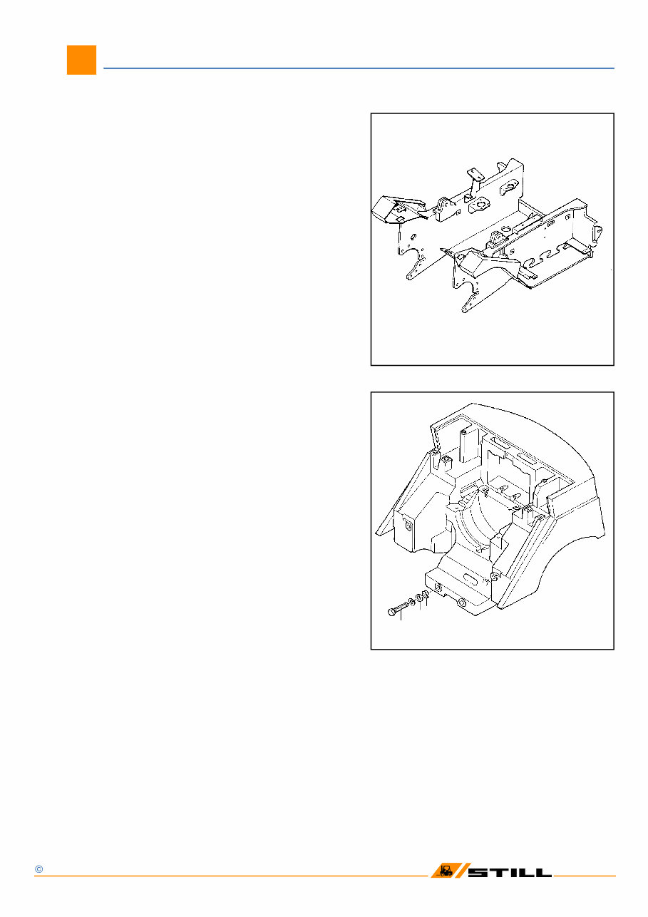
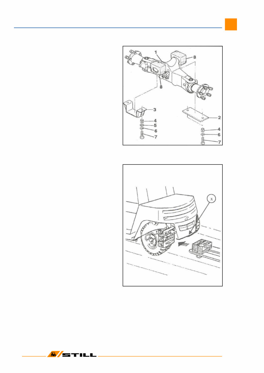
01 Workshop Manual 7032 - 34 / 38 - 40 / 48 - 50 Chassis Frame and Counterweight 01 STILL GmbH Stand: 2/1995 ( Ersatz für Stand: ) 1 2 3 4 Chassis Frame The chassis frame is constructed of electrically welded steel plate. Detachable fuel and hydraulic oil tanks are mounted inside left-hand and right-hand frame sections respectively for extra protection. Counterweight The removable rear counterweight is secured to the frame weldment by 4 bolts. 1 = hex hd bolt M24x130, 8.8 DIN 933 Torque loading: 710 Nm 2 = lock ring 3 = spherical washer C 25 DIN 6319 4 = ball cup D 28 DIN 6319 Weight of the counterweight 7032/7038 = 1,170 kg 7033/7039 = 1,514 kg 7034/7040 = 1,915 kg 7048 = 1,985 kg 7049 = 2,395 kg 7050 = 2,715 kg
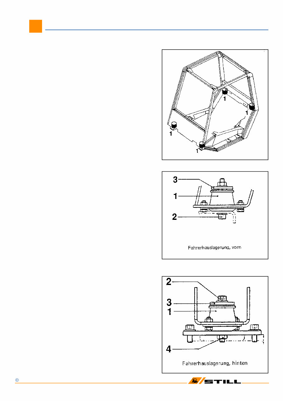
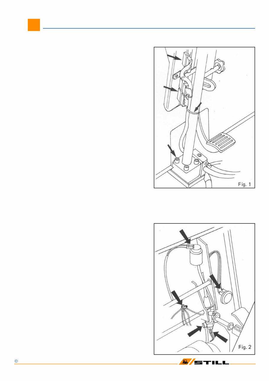
01 Workshop Manual 7032 - 34 / 38 - 40 / 48 - 50 Drivers cab 02 STILL GmbH Stand: 2/1995 ( Ersatz für Stand: ) Bolted to the frame at the front end and to the counterweight at the rear, the cab is mounted at 4 points on rubber type anti-vibration mounts. Removal - Remove panel from front cowl - Remove floor plate - Remove upswept type exhaust pipe (if fitted) - Remove cover plates left and right of inspec- tion plate, giving access to the rear rubber mounts (above counterweight) - Disconnect the 3 connectors at the steering column (Fig. 1, page 3) - Disconnect the wiring harness from the steer- ing column - Remove the screws which secure steering column to hand pump (steering wheel opera- ted pump) - Fig. 1, page 3) - Disconnect the connections on warning horn, brake fluid reservoir and master cylinder, located in the front cowl (Fig. 2, page 3) 1 = rubber type anti-vibration mount 2 = allen screw M10 x 80, 8.8 3 = washer 4 = hex nut; welded to the support
01 Workshop Manual 7032 - 34 / 38 - 40 / 48 - 50 Drivers cab 03 STILL GmbH Stand: 2/1995 ( Ersatz für Stand: ) Drivers cab (removal) Detach earthing or ground connection Remove panel to which is mounted the electronic control unit inside front cowl Disconnect brake line at master cylinder (Figure 2). Refit fluid passage bolt to prevent brake fluid from flowing out Remove M10 x 80 allen screws front and rear Slig cab using an overhead hoist or remove cab with the aid of a second lift truck
02 Steer axle 1 Contents Page Technical Data for 1 Maintenance Service Mechanical configuration of Steer axle Steer axle removal 2 Steer axle installation 2 Wheel hub - Removal and 3 Dismantling Wheel hub - Reassembling and 3 Installation Wheel angle stop adjustment 4 Checking the steering angles 4 Stub axle - Removal and 5 Dismantling Stub axle - Reassembling and 6 Installation Lubricating the steer axle with 6 grease Track rod removal 7 Track rod installation 7 Steer cylinder removal 8 Steer cylinder installation 8 Workshop Manual 7032 - 34 / 38 - 40 / 48 - 50
02 Technical Data for Maintenance Service 3 Workshop Manual 7032 - 34 / 38 - 40 / 48 - 50 2 0 p u o r G l a n o i t c n u F e l x a r e e t S e l g n a k c o l l e e h W ° 2 8 - 0 8 n i - e o T m m 1 ± 0 r e b m a c l e e h W ° 0 l i a r T ° 0 r o f s g n i d a o l e u q r o T 0 4 - 8 3 / 4 3 - 2 3 0 7 b u h l e e h W m N 5 2 2 = A M g n i x i f e l x A m N 5 9 1 = A M s t u n l e e h W m N 5 2 4 = A M r o f s g n i d a o l e u q r o T 0 5 - 8 4 0 7 b u h l e e h W m N 0 7 4 = A M g n i x i f e l x A m N 5 9 1 = A M s t u n l e e h W m N 0 4 6 = A M s t n a c i r b u L s g n i r a e b b u h l e e h W m u i h t i l 0 2 - K 2 P K - 5 2 8 1 5 N I D o t F e s a e r G d e s a b p a o s m u i h t i l , 0 3 - K 2 P K - 5 2 8 1 5 N I D o t F e s a e r G d e s a b p a o s s g n i r a e b e l x a b u t S , 0 2 - N 2 F P K - 5 2 8 1 5 N I D o t L F e s a e r G d e s a b p a o s m u i h t i l 9 5 6 8 4 1 . o N t n e d I L L I T S
02 Steer axle 4 Configuration of steer axle The articulating steer axle suspended from the counterweight is mounted in 2 neoprene blocks. The stub axles are supported in the axle beam on tapered roller bearings. Steering is limited by stop screws on the stub axles. 1 axle beam 2+3 fixing plates 4 Tension sleeve (depending on design) 5 Washer (depending on design) 6 Lock ring 7 socket head screw 8 neoprene blocks Steer axle removal CAUTION: Remove steer axle only with mast in position on the truck! Risk of tipping! Prepare for oil spillage when M A = 195 Nm CAUTION: Do not swap hydraulic connec- tions left and right! Workshop Manual 7032 - 34 / 38 - 40 / 48 - 50
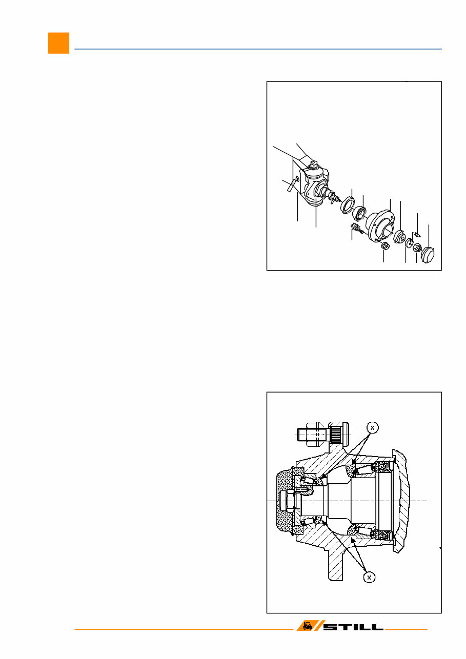
1 2 3 4 6 5 9 10 7 8 11 12 02 Steer axle 5 Wheel hub - Removal and Dismantling 1 axle beam 2 stub axle 3 radial sealing ring 4 tapered roller bearing 5 wheel hub 6 roll pin 7 hub cap 8 nut 9 washer 10 tapered roller bearing 11 wheel bolt 12 ball seat nut - Slacken ball seat nuts (12) and remove wheel. - Pull hub cap (7) from wheel. - Slacken nut (8) - Remove washer (9) with roll pin (6). - Withdraw the hub. - Remove radial sealing ring (3) then remove tapered roller bearings (4) and (10) from hub. - If necessary, drive out of wheel hub outer races of tapered roller bearings (4) and (10). Wheel hub - Reassembling and Installation - Apply a smear of grease to the sealing lips of the radial sealing ring. - Before re-assembling the hub, repack with grease F: cavity between inner race and bearing cage of tapered roller bearings, and the bearing spaces identified by an x on the drawing. - To reassemble the hubs, reverse the procedure. - Tighten nut (8) while rotating the wheel hub. Torque loading: 7032 - 34 / 38- 40 M A = 225 Nm 7048 - 50 M A = 470 Nm Workshop Manual 7032 - 34 / 38 - 40 / 48 - 50
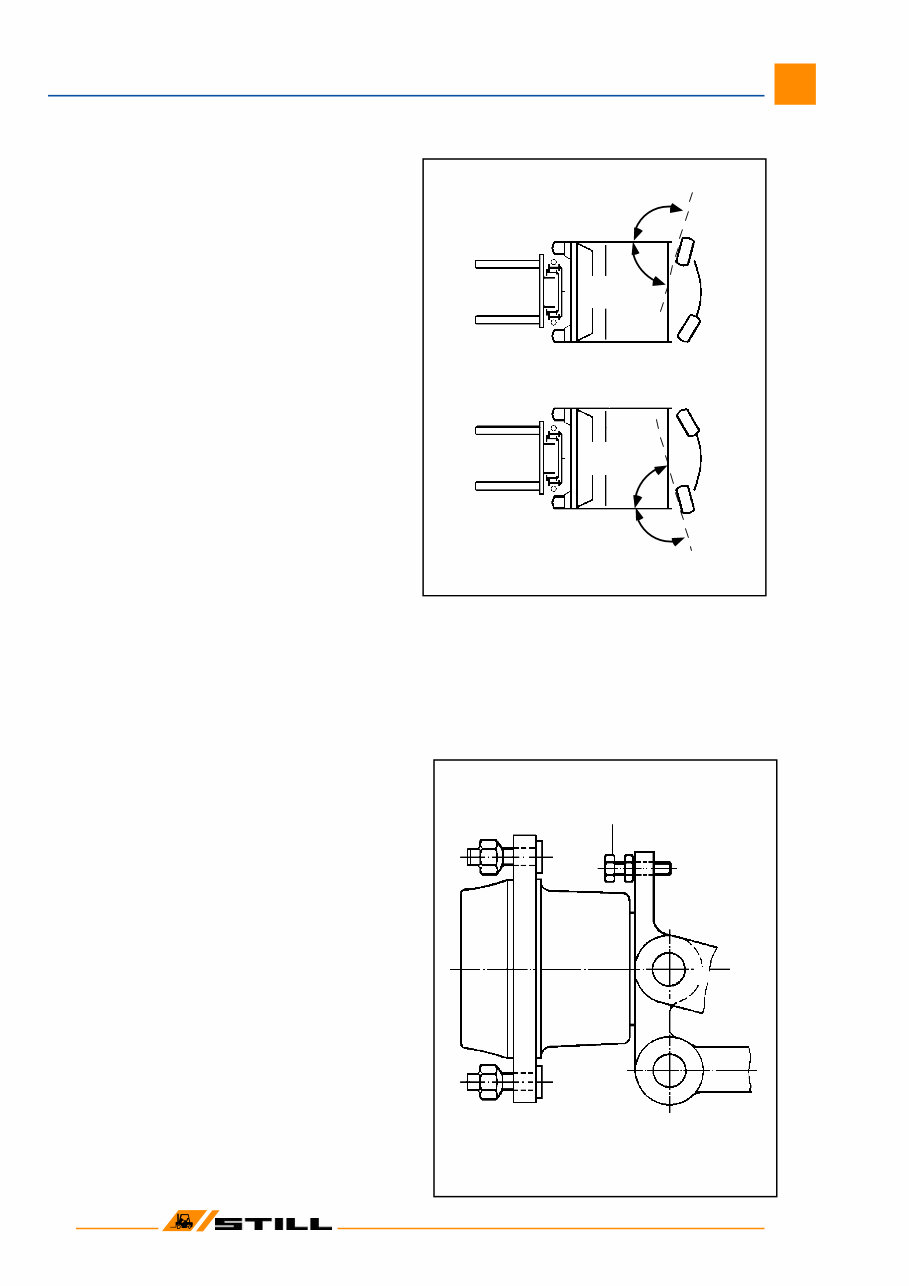
= 82° +0 / -2 1 Checking the steering angles The steering angle a must amount to 80° - 82°. To facilitate the measurement use the complementary angle b for the setting. It should amount to 98° - 100°. IMPORTANT: Ensure that the wheel lock is limited by the stop screws (1) and not by the cylinder stroke. Wheel angle stop adjustment The wheel stop angle is limited by the stop screws (1). - By operating on stop screws (1), set both steering angles to 80° - 82°. - Check opposite angles. - Check for adequate clearance between wheels and truck frame. 02 Steer axle 6 Workshop Manual 7032 - 34 / 38 - 40 / 48 - 50 Right-hand bend Left-hand bend steering lock
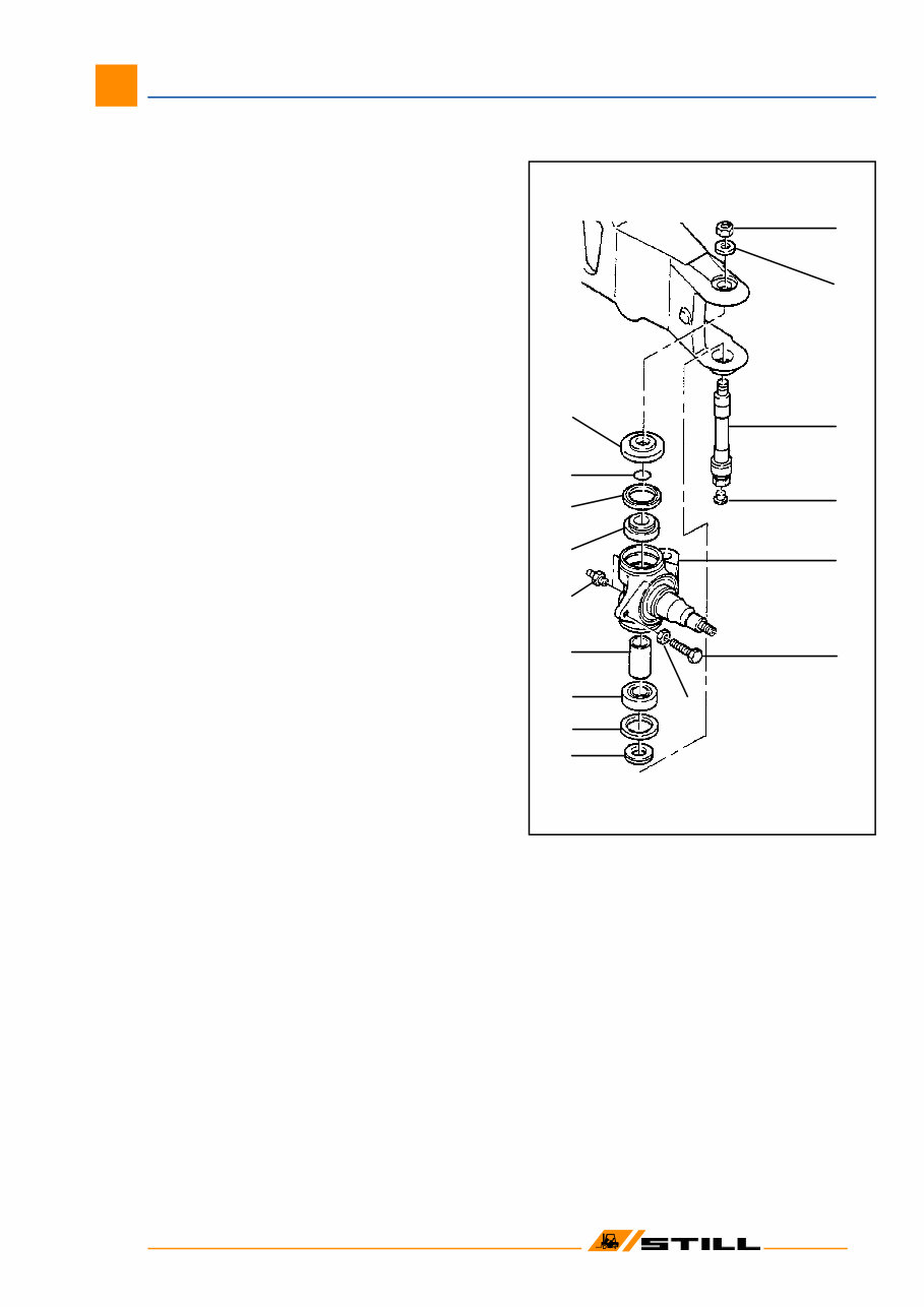
4 5 6 7 8 9 11 10 12 1 2 3 13 14 15 16 02 Steer axle 7 Stub axle - Removal and Dismantling 1 nut 2 washer 3 king pin 4 plug 5 stub axle 6 hex. hd. screw 7 nut 8 spacing washer 9 wiper ring 10 tapered roller bearing 11 spacer 12 grease nipple 13 tapered roller bearing 14 wiper ring 15 O-Ring 16 spacing washer - Remove the wheel. - Press out the pin located between track rod and stub axle. - Slacken nut (1). - Remove washer (2). - Press the king pin (3) down through the stub axle and remove the king pin. - Remove the stub axle from the axle. - Remove from the stub axle: spacing washers, O ring, wiper rings, tapered roller bearings and spacer (items 8-16). Workshop Manual 7032 - 34 / 38 - 40 / 48 - 50
These illustrated factory workshop manuals for Still Forklift Trucks are essential resources for both professional mechanics and DIY enthusiasts. They contain high-quality images, circuit diagrams, and detailed instructions to assist in the operation and repair of the trucks. The manuals are printable and searchable, making it easy to access the information you need.
The manuals cover a range of models including DFG R7032, DFG R7033, DFG R7034, DFG R7048, DFG R7049, DFG R7050, TFG R7038, TFG R7039, and TFG R7040. They are available in English and come in a PDF format with 512 pages.
The contents of the manuals include detailed information on various components and systems such as the steer axle, power axle, wheels and tires, steering, brakes, electrical installations, maintenance, drive motor, generator, external fan cooling, brush wear monitoring facility, thermal monitoring, pressure regulator, diesel engine, elevating mast, fork carriage, fork arm, mast pivots, and tilt cylinder.
Detailed information on various components and systems
These manuals provide comprehensive guidance for maintaining and repairing Still Fork Truck models, making them indispensable resources for anyone working with these vehicles.