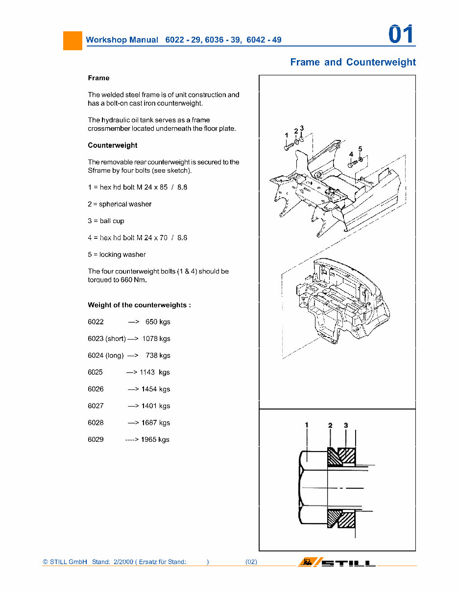
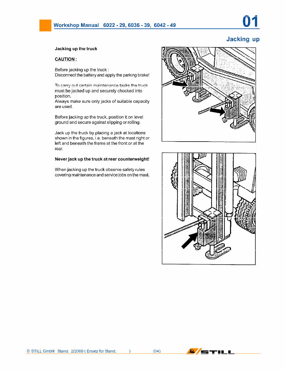
Workshop Manual 6022 - 29, 6036 - 39, 6042 - 49 01 Frame The welded steel frame is of unit construction and has a bolt-on cast iron counterweight. The hydraulic oil tank serves as a frame crossmember located underneath the floor plate. Counterweight The removable rear counterweight is secured to the Sframe by four bolts (see sketch). 1 = hex hd bolt M 24 x 85 / 8.8 2 = spherical washer 3 = ball cup 4 = hex hd bolt M 24 x 70 / 8.8 5 = locking washer The four counterweight bolts (1 & 4) should be torqued to 660 Nm. Weight of the counterweights : 6022 —> 650 kgs 6023 (short) —> 1078 kgs 6024 (long) —> 738 kgs 6025 6026 6027 6028 6029 —> 1143 kgs —> 1454 kgs —> 1401 kgs —> 1687 kgs —> 1965 kgs Frame and Counterweight ' STILL GmbH Stand: 2/2000 ( Ersatz fur Stand:
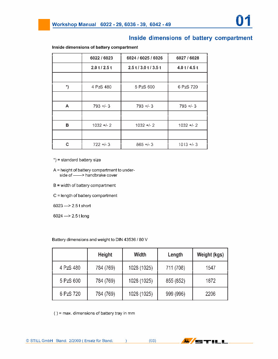
Workshop Manual 6022 - 29, 6036 - 39, 6042 - 49 01 Inside dimensions of battery compartment Inside dimensions of battery compartment 6022 / 6023 6024 / 6025 / 6026 6027 / 6028 2.0 t/ 2.5 t 2.5 t / 3.0 t / 3.5 t 4.0 t / 4.5 t *) 4 PzS 480 5 PzS 600 6 PzS 720 A 793 +/- 3 793 +/- 3 793 +/- 3 B 1032 +1-2 1032 +1-2 1032 +1-2 C 722 +/- 3 865 +/- 3 1013 +1-3 *) = standard battery size A = height of battery compartment to under¬ side of - > handbrake cover B = width of battery compartment C = length of battery compartment 6023 —> 2.5 t short 6024 —> 2.5 1long Battery dimensions and weight to DIN 43536 / 80 V Height Width Length Weight (kgs) 4 PzS 480 784 (769) 1028 (1025) 711 (708) 1547 5 PzS 600 784 (769) 1028 (1025) 855 (852) 1872 6 PzS 720 784 (769) 1028 (1025) 999 (996) 2206 () = max. dimensions of battery tray in mm ' STILL GmbH Stand: 2/2000 ( Ersatz fur Stand: (031 'll_L
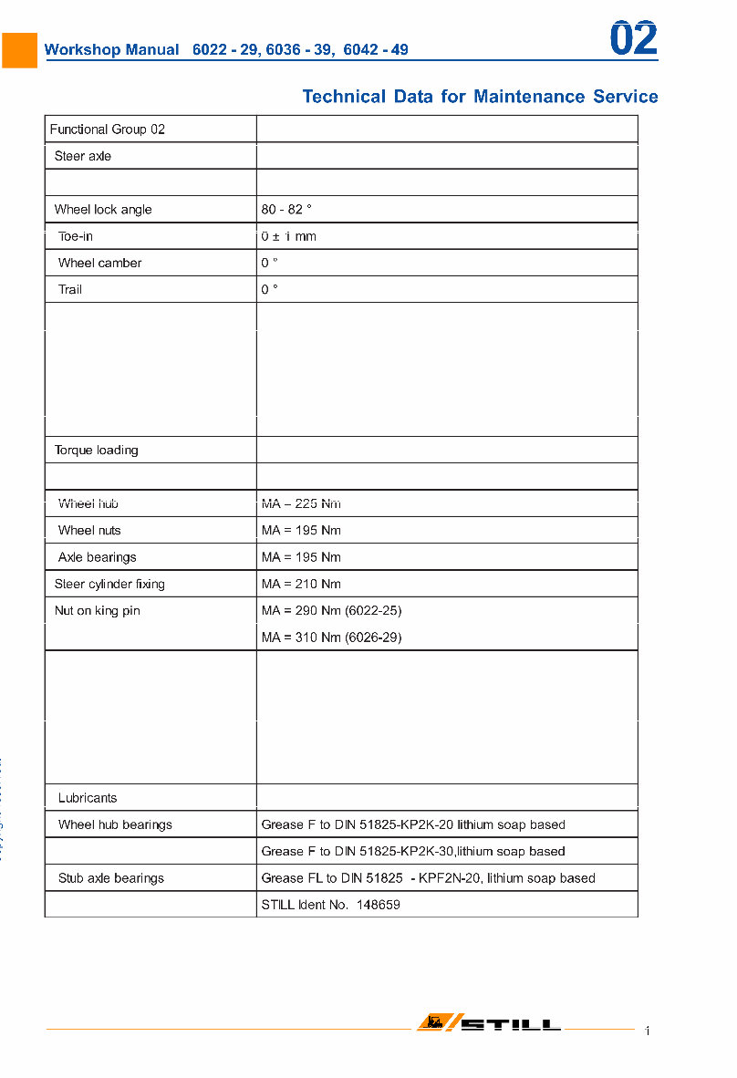
Workshop Manual 6022 - 29, 6036 - 39, 6042 - 49 02 Technical Data for Maintenance Service >, L 0 o Functional Group 02 Steer axle Wheel lock angle 0 CM 00 i o CO Toe-in 0 ± 1 mm Wheel camber 0 0 Trail 0 0 Torque loading Wheel hub MA = 225 Nm Wheel nuts MA = 195 Nm Axle bearings MA = 195 Nm Steer cylinder fixing MA = 210 Nm Nut on king pin MA = 290 Nm (6022-25) MA = 310 Nm (6026-29) Lubricants Wheel hub bearings Grease F to DIN 51825-KP2K-20 lithium soap based Grease F to DIN 51825-KP2K-30,lithium soap based Stub axle bearings Grease FLto DIN 51825 - KPF2N-20, lithium soap based STILL Ident No. 148659 M 5TILI
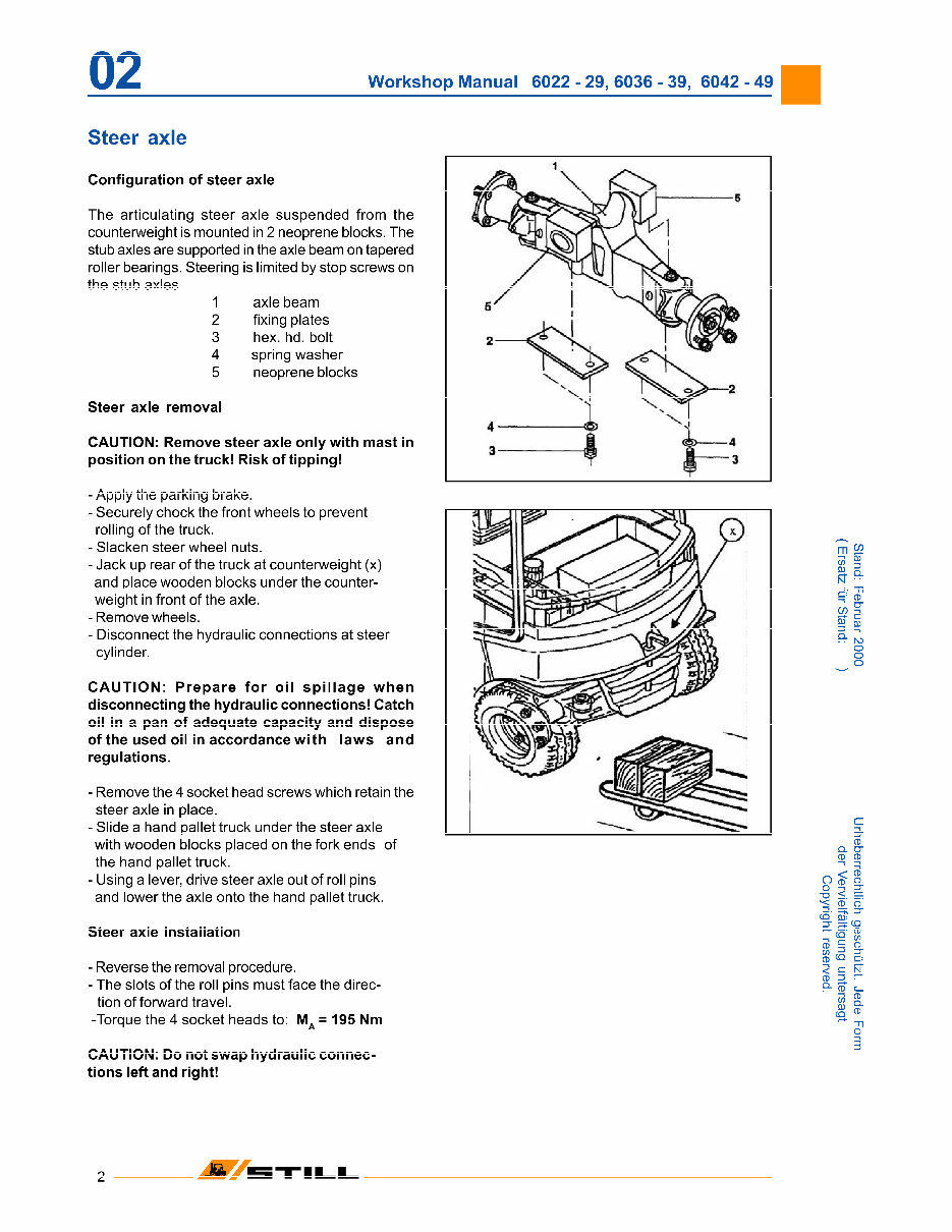
02 Workshop Manual 6022 - 29, 6036 - 39, 6042 - 49 Steer axle Configuration of steer axle The articulating steer axle suspended from the counterweight is mounted in 2 neoprene blocks. The stub axles are supported in the axle beam on tapered roller bearings. Steering is limited by stop screws on the stub axles. 1 axle beam 2 fixing plates 3 hex. hd. bolt 4 spring washer 5 neoprene blocks Steer axle removal CAUTION: Remove steer axle only with mast in position on the truck! Risk of tipping! - Apply the parking brake. - Securely chock the front wheels to prevent rolling of the truck. - Slacken steer wheel nuts. - Jack up rear of the truck at counterweight (x) and place wooden blocks under the counter¬ weight in front of the axle. -Remove wheels. - Disconnect the hydraulic connections at steer cylinder. CAUTION: Prepare for oil spillage when disconnecting the hydraulic connections! Catch oil in a pan of adequate capacity and dispose of the used oil in accordance with laws and regulations. - Remove the 4 socket head screws which retain the steer axle in place. - Slide a hand pallet truck under the steer axle with wooden blocks placed on the fork ends of the hand pallet truck. - Using a lever, drive steer axle out of roll pins and lower the axle onto the hand pallet truck. Steer axle installation - Reverse the removal procedure. - The slots of the roll pins must face the direc¬ tion of forward travel. -Torque the 4 socket heads to: MA = 195 Nm CAUTION: Do not swap hydraulic connec¬ tions left and right! m <£ a S- N 1 1 0) c/> of N5 O O o CD Q. O" CD CD _ < S Ojn "o < = % CD O ÿ T CQ Q): =T ÿ CQ <-r" rr\ A? C: 3 C_ CD CD- CD ~n o 3 INSTILL
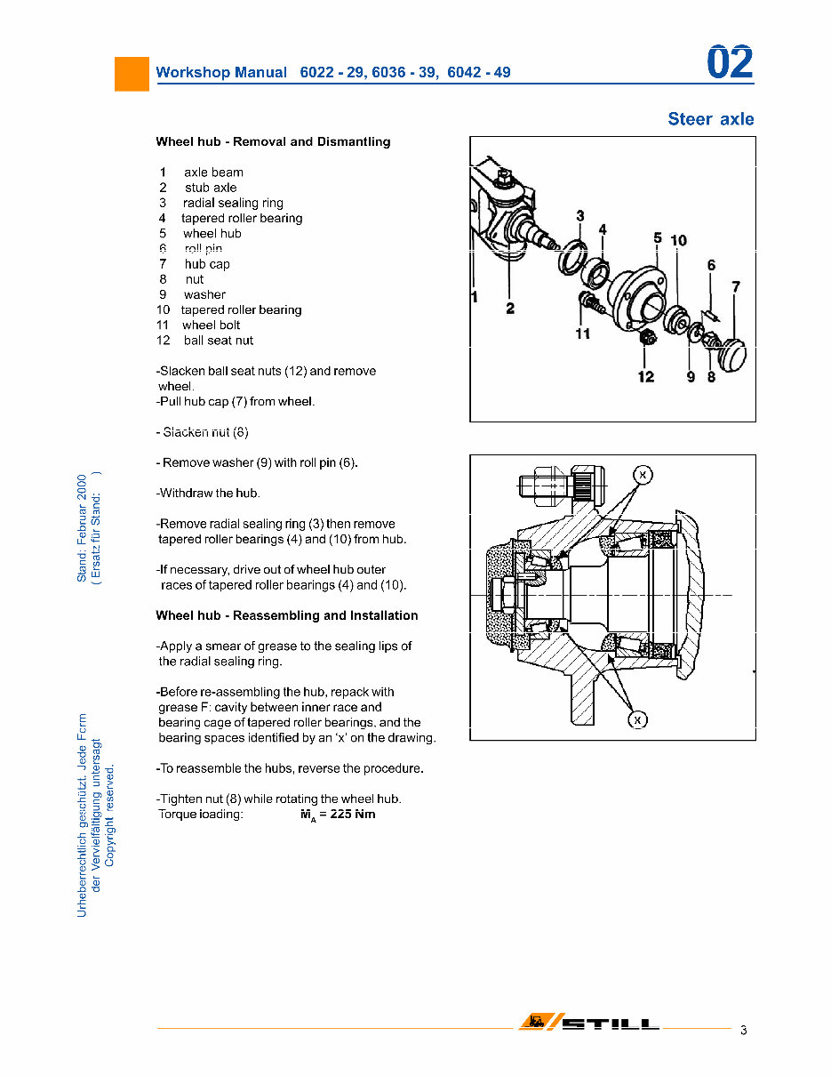
Workshop Manual 6022 - 29, 6036 - 39, 6042 - 49 02 Steer axle o o o CM -b »- c CD CD _Q 0 C/) C/) E o u_ ÿ 0 S3 -7-T 0 ® 2 jU T> c 0 N 13 > O Q) 0 -C c w 050 0 05 jcp g) o -35 >, 5 > Q- r ÿ o o P O 0 > i_ 00 -Q "D 0 Wheel hub - Removal and Dismantling 1 axle beam 2 stub axle 3 radial sealing ring 4 tapered roller bearing 5 wheel hub 6 roll pin 7 hub cap 8 nut 9 washer 10 tapered roller bearing 11 wheel bolt 12 ball seat nut -Slacken ball seat nuts (12) and remove wheel. -Pull hub cap (7) from wheel. - Slacken nut (8) - Remove washer (9) with roll pin (6). -Withdraw the hub. -Remove radial sealing ring (3) then remove tapered roller bearings (4) and (10) from hub. -If necessary, drive out of wheel hub outer races of tapered roller bearings (4) and (10). Wheel hub - Reassembling and Installation -Apply a smear of grease to the sealing lips of the radial sealing ring. -Before re-assembling the hub, repack with grease F: cavity between inner race and bearing cage of tapered roller bearings, and the bearing spaces identified by an 'x' on the drawing. -To reassemble the hubs, reverse the procedure. -Tighten nut (8) while rotating the wheel hub. Torque loading: MA = 225Nm M 5TILI
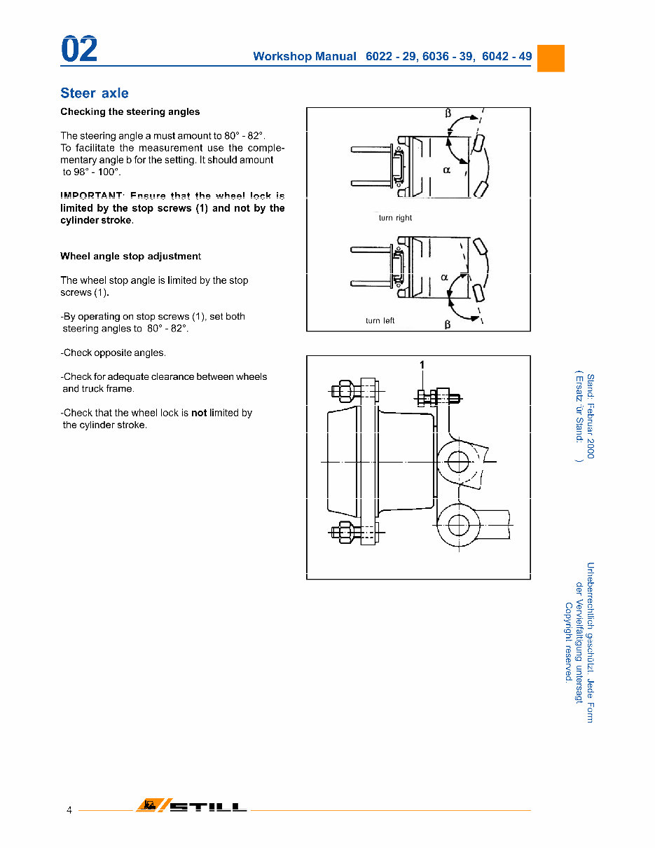
02 Workshop Manual 6022 - 29, 6036 - 39, 6042 - 49 Steer axle Checking the steering angles The steering angle a must amount to 80° - 82°. To facilitate the measurement use the comple¬ mentary angle b for the setting. It should amount to 98° -100°. IMPORTANT: Ensure that the wheel lock is limited by the stop screws (1) and not by the cylinder stroke. Wheel angle stop adjustment The wheel stop angle is limited by the stop screws (1). -By operating on stop screws (1), set both steering angles to 80° - 82°. -Check opposite angles. -Check for adequate clearance between wheels and truck frame. -Check that the wheel lock is not limited by the cylinder stroke. turn right turn left m 92 w § K- Q- N • CD CO 5T N5 o o o CD Q. O" CD CD _ < S Ojn "O < =: % CD O ÿ T CQ Q): =T ÿ CD <-r" rn" A? C: s C_ CD Q. CD ~n o 3 INSTILL
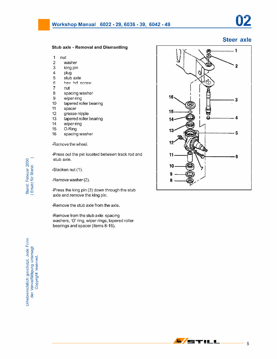
Workshop Manual 6022 - 29, 6036 - 39, 6042 - 49 02 Steer axle "O 1- c ra to .a aj W Stub axle - Removal and Dismantling 1 nut 2 washer 3 king pin 4 plug 5 stub axle 6 hex. hd. screw 7 nut 8 spacing washer 9 wiper ring 10 tapered roller bearing 11 spacer 12 grease nipple 13 tapered roller bearing 14 wiper ring 15 O-Ring 16 spacing washer w -Remove the wheel. -Press out the pin located between track rod and stub axle. -Slacken nut(1). -Remove washer (2). -Press the king pin (3) down through the stub axle and remove the king pin. I VC \ (3 1 K ÿÿ2 n 0 15— | A • ÿ 0 11 i J 0 10 - 0 ÿ 9 » «£• E o LL „ CD -7-T CO o £ jU t> c 0 N 13 > O Q) 0 sz F- <S> O§0 w O) 0 05 jro g) o -35 >, 5 > Q- _c £ ° o P O 0 > i_ 00 -Q "D 0 -Remove the stub axle from the axle. -Remove from the stub axle: spacing washers, 'O' ring, wiper rings, tapered roller bearings and spacer (items 8-16). ÿ 5TILI
Get your hands on the illustrated factory workshop manual for Still Electric Forklift Truck Type R60-20, R60-22, R60-25, R60-30, R60-35, R60-40, R60-45, R60-50. This original factory manual is a valuable resource for both professional mechanics and DIY enthusiasts. It contains high-quality images, circuit diagrams, and detailed instructions to assist you in the operation and repair of your forklift truck.
The manual covers a range of models including R6022, R6023, R6024, R6025, R6026, R6027, R6028, R6029, R6036I, R6037I, R6038I, R6039I, R6042, R6043, R6044, R6045, R6046, R6047, R6048, and R6049. With 251 pages of comprehensive content, it is available in English language.
The manual includes detailed information on various components and systems such as frame and counterweight, steer axle, power axle, steering, service brake, electrical installation, configuration of optional electrical equipment, hydraulic system, drive motor, pressure regulator I and II function, and mast unit (20-25).
Whether you need to troubleshoot an issue or perform routine maintenance, this manual is a must-have reference for anyone working with Still Electric Forklift Trucks.
Recently Viewed
5,521,897Happy Clients
2,594,462eManuals
1,120,453Trusted Sellers
15Years in Business
Price:
Actual Price:
Still Electric Forklift Truck Type R60-20, R60-22, R60-25, R60-30, R60-35, R60-40, R60-45, R60-50 Workshop Manual