



ce
R50-10 R50-12
R50-15/16
Elektro Gabelstapler
Electric Fork Truck
Chariot elevateur electrique
Carretilla elevadora elettrica
u
<
Is
_i h
ÿ
-i
o
>
(A
111 Q (A
V)
D
in
STILLGmbH
Werk-
statt-
handbuch
Work¬
shop
manual
R5001-R5034
Ident-Nr.164534 (en)
Manuel
d 'Atelier
Manual
de taller
Workshop Manual 5001 -34
Frame and counterweight
The rigid electrically welded steel plate chassis frame
and body is of unit construction and has a bolted-on
type counterweight.
The hydraulic oil tank forms an integral part of the
frame, and is situated between the leg and battery
compartments.
The removable rear counterweight has fixing holes
through which pass the screws with hexagonal
recessed hole holding the power unit in place.
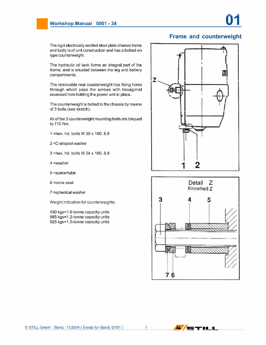
The counterweight is bolted to the chassis by means
of 3 bolts (see sketch).
All of the 3 counterweight mounting bolts are torqued
to 710 Nm.
1 =hex. hd. bolts M 30 x 100, 8.8
2 =C-shaped washer
3 =hex. hd. bolts M 24 x 160, 8.8
4 =washer
5 =spacertube
6 =cone seat
7 ÿspherical washer
Weight indication for counterweights:
490 kgs=1.0-tonne capacity units
685 kgs=1,2-tonne capacity units
925 kgs=1
,5-tonne
capacity units
z
1
2
Detail Z
EinzellieilZ
i i
STILL GmbH Stand: 11/2004 ( Ersatz fur Stand: 07/91 )
'll_L
Workshop Manual 5001 -34 01
Frame and counterweight
without roller frame* with roller frame*
1.0-tonne unit
Cushion lyres
supereiaslic
tyres
10 tonne unit
pneumatic &
supereiastic
lyres
12 lor*
Cushion
tyres
leuoil
Poeurn,
ÿ
SF
1.5-to
Cushion
lyres
nnc unit
Fneum.
+ SE
a Top oi silent blocks** to
"
lop ol remnvahtn side plate
(mm)
640
ÿ
4
640
+ 4
640
*4
640
+4
~
W
640 ÿ4 64°
•}
p Top ol silent blocks'* to on
der side ot hood frnm)
065 ÿ3 665
I*
665*3 665+3 B65
+3
665
+3
p Length ol battery compart-
merit area (mm)
352
*
3
470
*3
470
*3
470
+3
506
+3
S06
ÿ
3
n Width ol battery compart-
merit (mm|
859 t5 859 15 859 t 5 Ub8
*
b 859 x 5 859 t 5
E
Ground to top ol rof er Irame 177 t5 187 a: 3 1//t3 18/ ±3 177 *3 187+3
p lop ot roller platform to lop
ol removable side plate (mm)
6I3
+ 6
-
s
613
*
| 613
1
5
613+6 613+6
613 +G
5
Top Ol roller platlorm to un
der side of cover jmm)
638 f§
4
638
+
§
- 4
630
*5
- 4
638
+5
- 4
038
+5
-
4
638
ÿ
5
-4
U
Distance between LH side
M Iratne section and battery
latch (mm)
830
*_l
836 830
: jj
836 »|
-6
836
836
•
5
-6
ÿ Dstance between long chan
J net bars ol chassis frame
(mm)
590
ÿ
3 590
ÿ
3 590 + 3 590
+ 3 590 1 3 590 t 3
l(
Weight ibqu red in battery
compart monl (kgs)***
451 451 567 58/ 65/ 057
|
ienat n ol hat I ery compart -
ment (mm) with extra ballast
~
445
'
3
- 4
440
'
3
- 4
481
1
3
-
4
481
'
3
-
4
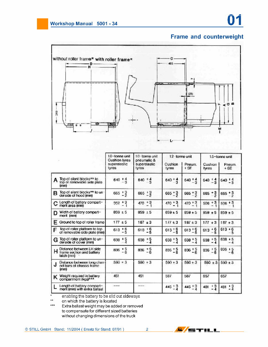
enabling the battery to be slid out sideways
on which the battery is located
*** Extra ballast weight may be added or removed
to compensate for different sized batteries
without changing dimensions of the truck
STILL GmbH Stand: 11/2004 ( Ersatz fur Stand: 07/91 )
'll_L
Workshop Manual 5001 -34
Front axle
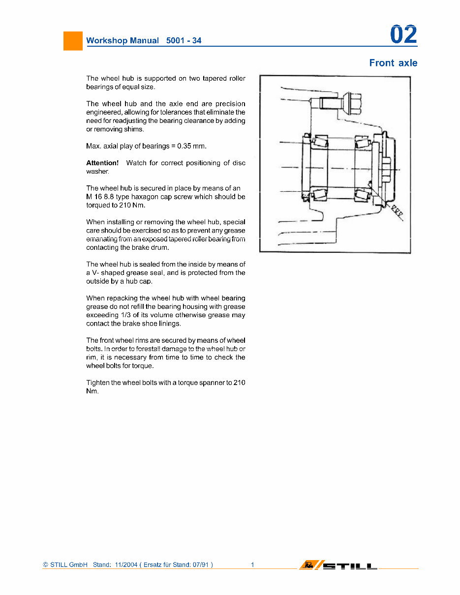
The wheel hub is supported on two tapered roller
bearings of equal size.
The wheel hub and the axle end are precision
engineered, allowing for tolerances that eliminate the
need for readjusting the bearing clearance by adding
or removing shims.
Max. axial play of bearings = 0.35 mm.
Attention! Watch for correct positioning of disc
washer.
The wheel hub is secured in place by means of an
M 16 8.8 type haxagon cap screw which should be
torqued to 210 Nm.
When installing or removing the wheel hub, special
care should be exercised so as to prevent any grease
emanating from an exposed tapered roller bearing from
contacting the brake drum.
The wheel hub is sealed from the inside by means of
a V- shaped grease seal, and is protected from the
outside by a hub cap.
When repacking the wheel hub with wheel bearing
grease do not refill the bearing housing with grease
exceeding 1/3 of its volume otherwise grease may
contact the brake shoe linings.
The front wheel rims are secured by means of wheel
bolts. In order to forestall damage to the wheel hub or
rim, it is necessary from time to time to check the
wheel bolts for torque.
Tighten the wheel bolts with a torque spanner to 210
Nm.
STILL GmbH Stand: 11/2004 ( Ersatz fur Stand: 07/91 )
'll_L
Workshop Manual 5001 -34 03
Power unit
Transmission type:
Gearbox capacity:
Grade of oil:
Spur-type reduction
gear
1.5 litres
High-pressure
transmission oil
(OG to MIL - L 2106)
SAE 80
Power from the horizontally arranged D.C. drive motor
is transmitted to the drive/steer wheel via a triple
reduction precision gear drive operating in an oil bath.
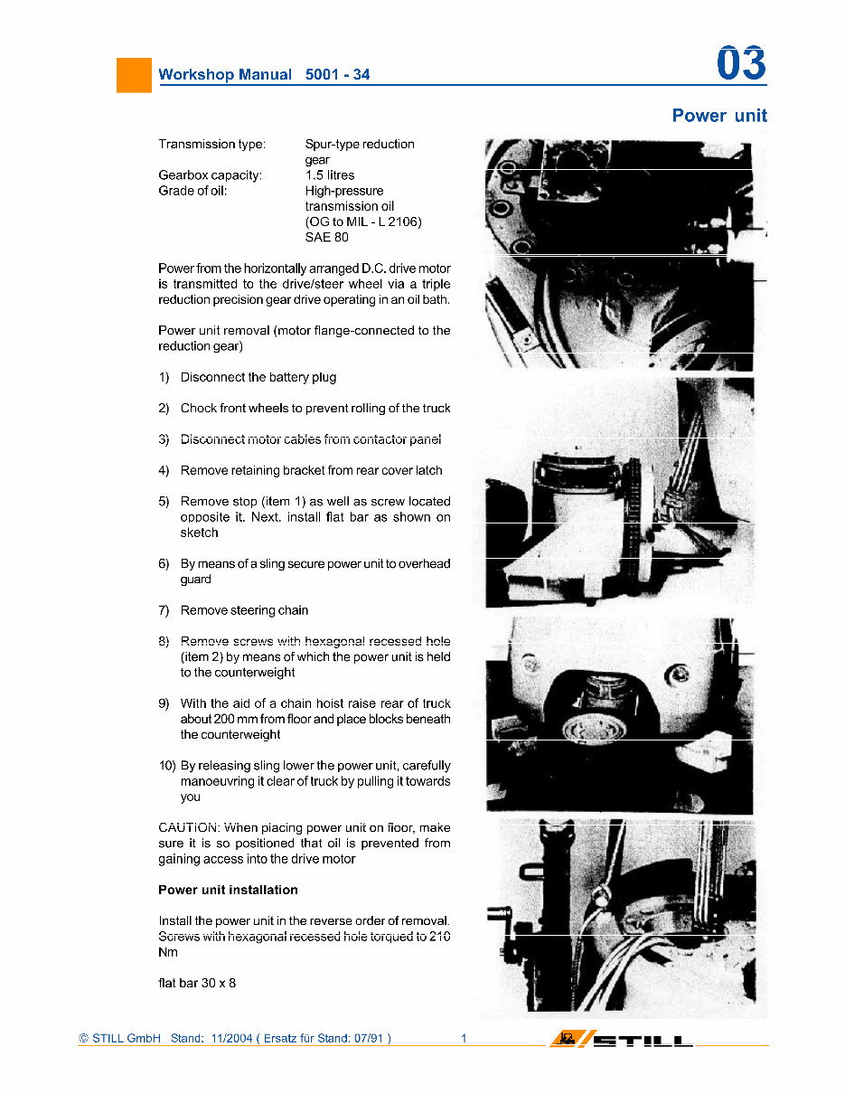
Power unit removal (motor flange-connected to the
reduction gear)
1) Disconnect the battery plug
2) Chock front wheels to prevent rolling of the truck
3) Disconnect motor cables from contactor panel
4) Remove retaining bracket from rear cover latch
5) Remove stop (item 1) as well as screw located
opposite it. Next, install flat bar as shown on
sketch
6) By means of a sling secure power unit to overhead
guard
7) Remove steering chain
8) Remove screws with hexagonal recessed hole
(item 2) by means of which the power unit is held
to the counterweight
9) With the aid of a chain hoist raise rear of truck
about 200 mm from floor and place blocks beneath
the counterweight
10) By releasing sling lower the power unit, carefully
manoeuvring it clear of truck by pulling it towards
you
CAUTION: When placing power unit on floor, make
sure it is so positioned that oil is prevented from
gaining access into the drive motor
Power unit installation
Install the power unit in the reverse order of removal.
Screws with hexagonal recessed hole torqued to 210
Nm
flat bar 30 x 8
Vi
STILL GmbH Stand: 11/2004 ( Ersatz fur Stand: 07/91 )
'll_L
Workshop Manual 5001
-
34 03
Power unit
© STILL GmbH Stand: 11/2004 ( Ersatz fur Stand: 07/91 ) 2
M 5TI
Workshop Manual 5001 -34
Power unit
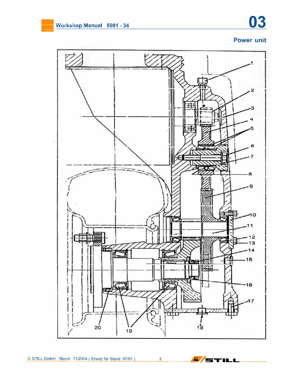
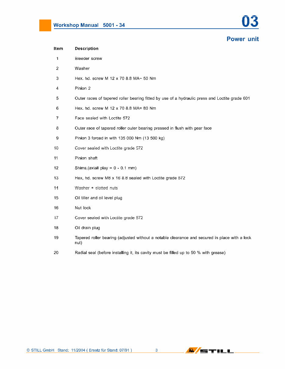
Item Description
1 Bleeder screw
2 Washer
3 Hex. hd. screw M 12 x 70 8.8 MA~ 50 Nm
4 Pinion 2
5 Outer races of tapered roller bearing fitted by use of a hydraulic press and Loctite grade 601
6 Hex. hd. screw M 12 x 70 8.8 MA= 80 Nm
7 Face sealed with Loctite 572
8 Outer race of tapered roller outer bearing pressed in flush with gear face
9 Pinion 3 forced in with 135 000 Nm (13 500 kg)
10 Cover sealed with Loctite grade 572
11 Pinion shaft
12 Shims,(axiall play = 0-0.1 mm)
13 Hex, hd. screw M8 x 16 8.8 sealed with Loctite grade 572
14 Washer + slotted nuts
15 Oil tiller and oil level plug
16 Nut lock
17 Cover sealed with Loctite grade 572
18 Oil drain plug
19 Tapered roller bearing (adjusted without a notable clearance and secured in place with a lock
nut)
20 Radial seal (before installing it, its cavity must be filled up to 50 % with grease)
STILL GmbH Stand: 11/2004 ( Ersatz fur Stand: 07/91 )
'll_L
Workshop Manual 5001 -34 04
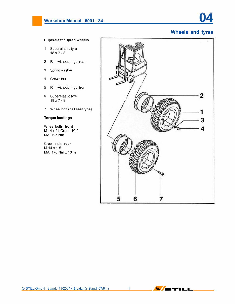
Superelastic tyred wheels
1 Superelastic tyre
18x7-8
2 Rim without rings- rear
3 Spring washer
4 Crown nut
5 Rim without rings- front
6 Superelastic tyre
18x7-8
7 Wheel bolt (ball seat type)
Torque loadings
Wheel bolts- front
M 14x24 Grade 10.9
MA: 195 Nm
Crown nuts- rear
M 14x 1.5
MA: 170 Nm ± 10 %
Wheels and tyres
© STILL GmbH Stand: 11/2004 ( Ersatz fur Stand: 07/91 ) 1
M 5TILI
Workshop Manual 5001 -34 06
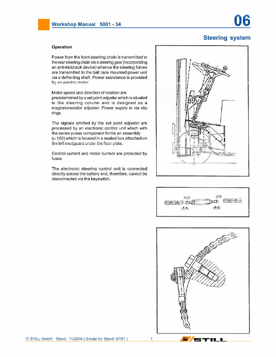
Operation
Power from the front steering chain is transmitted to
the rear steering chain via a steering gear (incorporating
an anti-kickback device) whence the steering forces
are transmitted to the ball race mounted power unit
via a deflecting shaft. Power assistance is provided
by an electric motor.
Motor speed and direction of rotation are
predetermined by a set point adjuster which is situated
in the steering column and is designed as a
magnetoresistor adjuster. Power supply is via slip
rings.
The signals emitted by the set point adjuster are
processed by an electronic control unit which with
the series power component forms an assembly
(u 100) which is housed in a sealed box attached on
the left mudguard under the floor plate.
Control current and motor current are protected by
fuses.
The electronic steering control unit is connected
directly across the battery and, therefore, cannot be
disconnected via the keyswitch.
Steering system
_
_ <£3 _
tfcfb
© STILL GmbH Stand: 11/2004 ( Ersatz fur Stand: 07/91 ) 1
5TILI
Workshop Manual 5001 -34
Steering
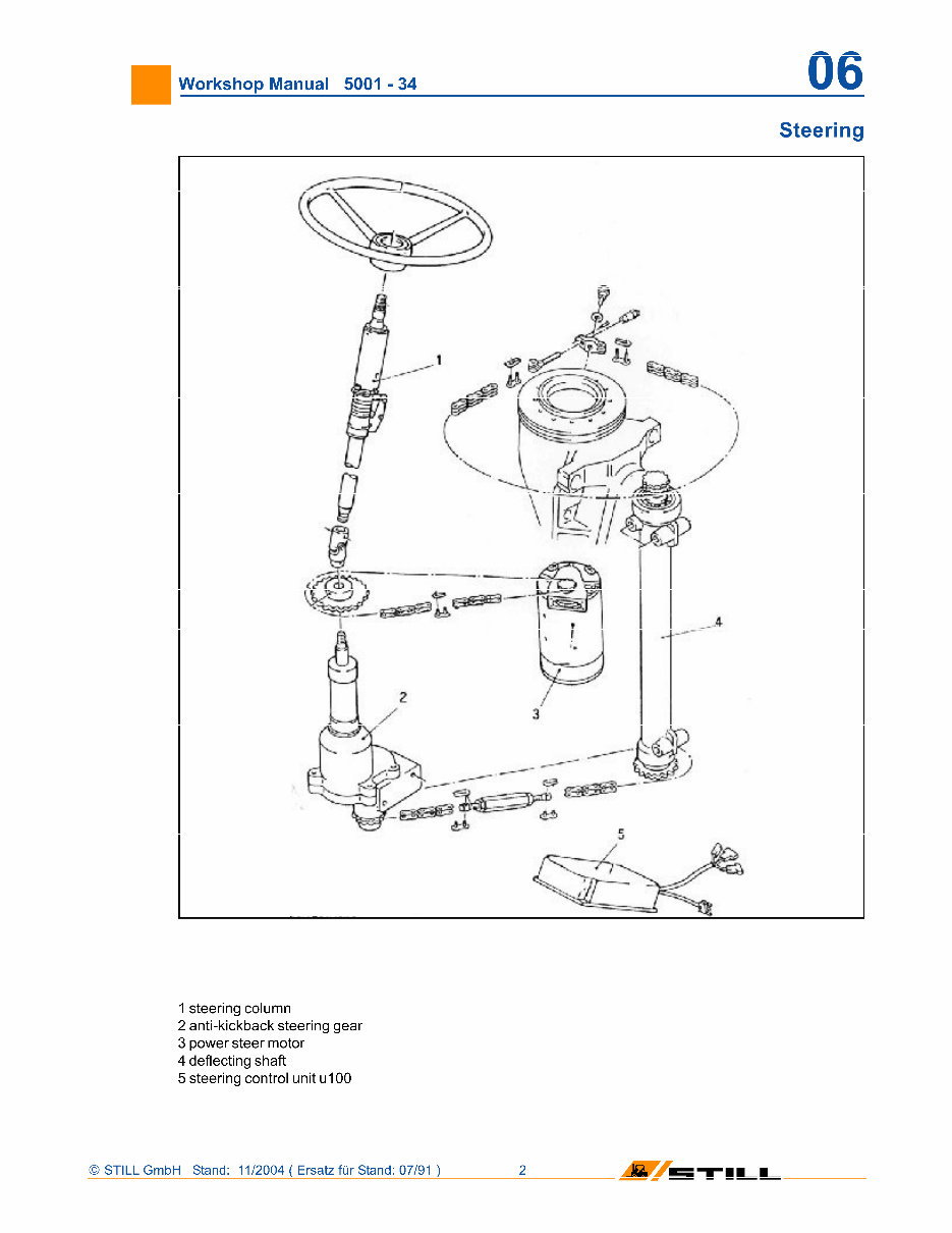
1 steering column
2 anti-kickback steering gear
3 power steer motor
4 deflecting shaft
5 steering control unit u100
© STILL GmbH Stand: 11/2004 ( Ersatz fur Stand: 07/91 ) 2
M 5TILI
You're Reading a Preview
What's Included?
 Lifetime Access
Fast Download Speeds
Online & Offline Access
Access PDF Contents & Bookmarks
Full Search Facility
Print one or all pages of your manual
$36.99
Still R50-10, R50-12, R50-15, R50-16 (R5001-R5034) Electric Fork Truck Service Workshop Manual
Viewed 11 Times Today

What's Included?
Lifetime Access
Fast Download Speeds
Online & Offline Access
Access PDF Contents & Bookmarks
Full Search Facility
Print one or all pages of your manual
$36.99

Secure transaction
What's Included?
Lifetime Access
Fast Download Speeds
Online & Offline Access
Access PDF Contents & Bookmarks
Full Search Facility
Print one or all pages of your manual
Description
- Covered models:
- R5001
- R5003
- R5004
- R5005
- R5006
- R5007
- R5008
- R5009
- R5010
- R5011
- R5012
- R5013
- R5014
- R5015
- R5016
- R5017
- R5018
- R5019
- R5020
- R5021
- R5022
- R5023
- R5024
- R5025
- R5026
- R5027
- R5028
- R5029
- R5030
- R5031
- R5032
- R5033
- R5034
- This manual can be used by anyone from a first time owner/amateur to a professional technician. It is easy to read and provides all the information needed to perform procedures correctly. Keeping this service manual handy and using it often is recommended. Performing routine, preventive maintenance will save time and money by helping to prevent premature failure and unnecessary repairs.
- Manual Contents:
- 01: Frame and counterweight
- 02: Front axle
- 03: Power unit
- 04: Wheels and Tyres
- 06: Steering System
- 07: Hydraulic Service Brake
- 08: Electrical Installation
- 09: Battery Discharge Indicator
- 10: Hydraulic System
- 11: Drive motor
- 13: Pressure Regulator Unit I and I
- 20: Elevating Mast
- 22: Fork carriage
- 23: Fork arm
- 24: Mast pivots
- 25: Tilt cylinder
- S-D: IMPORTANT TESTING HINTS for checking the electronic power control of the drive
- Total Pages: 172
- File Format: .PDF
- Compatible: All Versions of Windows & Mac
- Language: English
- Requirements: Adobe Reader & Win


