Still R20-15, R20-16, R20-18, R20-20 Series Electric Fork Truck Forklift Service Repair Workshop Manual
What's Included?
Lifetime Access
Fast Download Speeds
Online & Offline Access
Access PDF Contents & Bookmarks
Full Search Facility
Print one or all pages of your manual
STILLGmbH R20-15 R20-16 Werk- statt- handbuch Work- shop manual Manuel d´Atelier R2008-2014 R2015 R2045 -2048 I I I R2017-2024 R2037-2044 R20-18 R20-20 Elektro Gabelstapler Electric Fork Truck Chariot élévateur électrique Carretilla elevadora elettrica Manual de taller Ident-Nr.164526 (en)
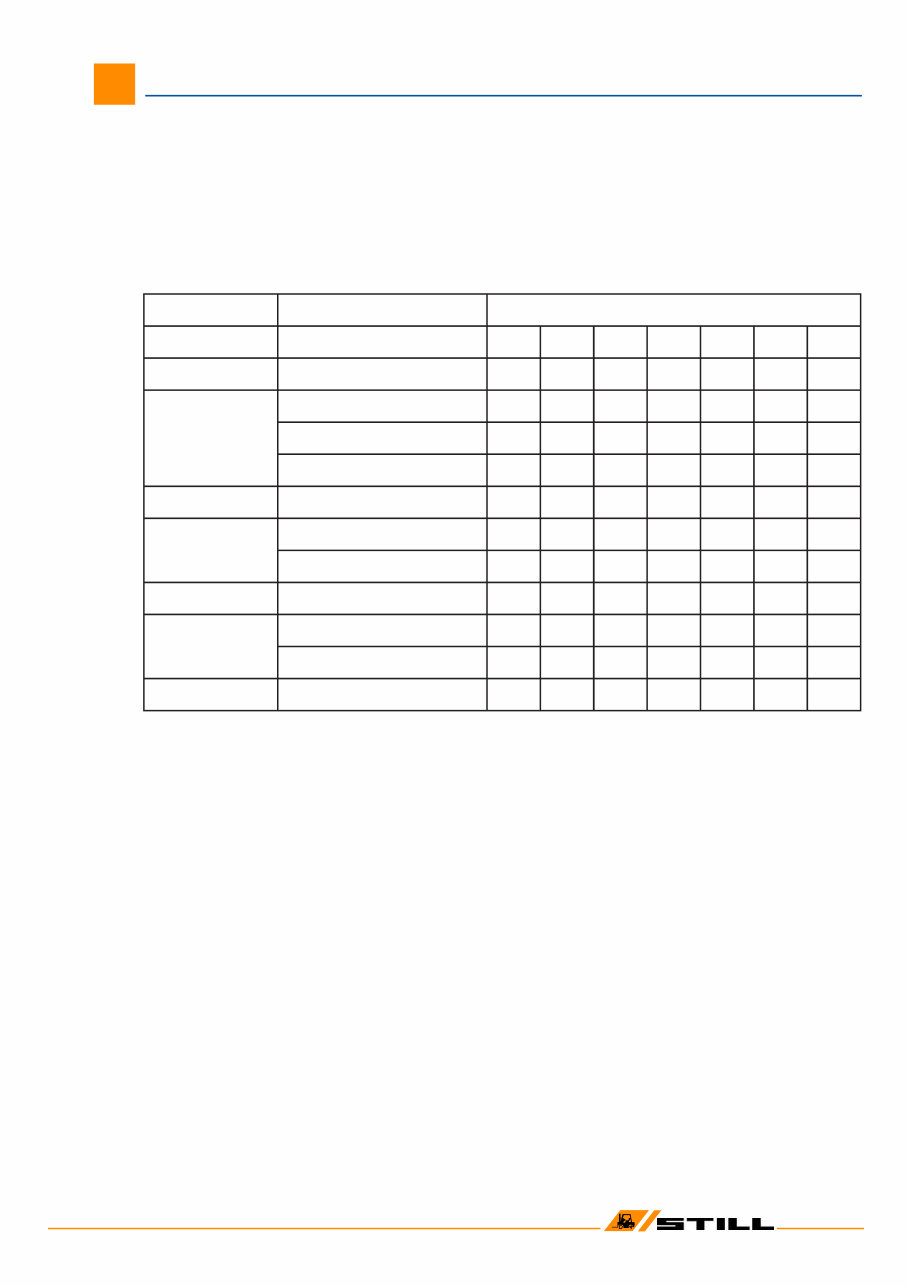
! STILL GmbH Stand: 11/2003 ( Ersatz für Stand: ) Workshop Manual R20-14 – R20-20, R20-15i – R20-18i Information relating to workshop manual I The workshop manual is valid for all of the listed trucks. This workshop manual has been prepared for the truck types 2008 - 2014. For newer truck types, supplements will be provided in case of deviations. The supplements will include valid truck types. n o i t a n g i s e d n g i s e d p y t k c u r t 4 1 - 0 2 R e l b a t n r u T 7 1 0 2 7 3 0 2 5 1 - 0 2 R t r o h s , e l b a t n r u T 8 0 0 2 8 1 0 2 8 3 0 2 6 1 - 0 2 R t r o h s , e l x a g n i w S 9 0 0 2 9 1 0 2 9 3 0 2 e l b a t n r u T 0 1 0 2 0 2 0 2 0 4 0 2 e l x a g n i w S 3 1 0 2 3 2 0 2 3 4 0 2 8 1 - 0 2 R e l b a t n r u T 1 1 0 2 1 2 0 2 1 4 0 2 0 2 - 0 2 R e l x a g n i w S 2 1 0 2 2 2 0 2 2 4 0 2 e l b a t n r u T 4 1 0 2 4 2 0 2 4 4 0 2 i 5 1 - 0 2 R ) C A ( t r o h s , e l b a t n r u T 5 1 0 2 5 4 0 2 i 6 1 - 0 2 R ) C A ( e l b a t n r u T 6 4 0 2 ) C A ( e l x a g n i w S 7 4 0 2 i 8 1 - 0 2 R ) C A ( e l b a t n r u T 8 4 0 2
STILL GmbH Position as per: 4/2002 ( Replaces version: ) 01 Workshop Manual 2008 - 14, 2015 i, 2018 - 24 01 Table of Contents Page Frame and Counterweight 2 Jacking up the truck 3 Chassis Frame
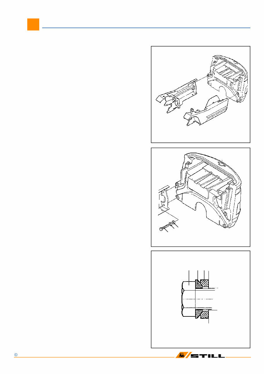
STILL GmbH Position as per: 4/2002 ( Replaces version: ) 01 Workshop Manual 2008 - 14, 2015 i, 2018 - 24 Frame and counterweight 02 Frame The welded steel frame is of unit instruction and has bolt-on cast iron counterweight. Counterweight The removable counterweight is secured to the frame by four bolts (see sketch). 1 = Hex head bolt M 24 x 110 / 8.8 2 = Spherical washer 3 = Ball cup The counterweight bolts(item 1) should be tor- qued to 660 Nm. 2010 -- 798 kg 2008 / 2011 -- 858 kg 2009 / 2012 -- 902 kg 2013 / 2014 -- 902 kg 2015 / 2018 -- 861 kg 2019 / 2022 / 2023 -- 891 kg 2020 -- 832 kg 2021 -- 875 kg 2024 -- 1009 kg 1 2 3 1 2 3
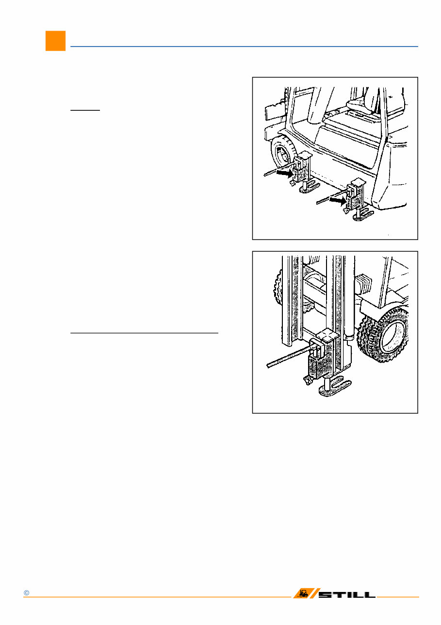
STILL GmbH Position as per: 4/2002 ( Replaces version: ) 01 Workshop Manual 2008 - 14, 2015 i, 2018 - 24 Jacking up 03 Caution: Before jacking up the truck: Disconnect thebattery plug ! Apply the parking brake ! To carry out certain maintenance tasks the truck must be jacked up. When jacked up, the truck must be securely chocked against slipping and tipping with suit- able means , e.g. wooden blocks. Always make sure only jacks of suitable capaci- ty are used and that the truck is jacked up on level ground and secured against rolling. Jack up the truck by placing a jack at locations shown in the figures, i.e. beneath the mast right or left and the frame at the front or at the rear. Do not jack up the truck at the counterweight! When jacking up the truck at the mast, observe the safety rules for work on the mast.
! STILL GmbH Position as per: 4/2002 ( Replaces version: ) 02 Workshop Manual 2008 - 14, 2015 i, 2018 - 24 01 Steer axle Table of content Page Steering turnable Technical Data for Maintenance Service 1 Steer axle - Mechanical configuration 2 Steer axle removal 3 Steer axle installation 3 Steering turnable bearings - Dismantling 4 Steering turnable bearings - Reassambly 5 Adjusting the end play of the axle shaft 6 Trail wheel hub - Dismantling 7 Trail wheel hub - Reassembly 7 Articulating steer axle Technical Data for Maintenance Service 9 Steer axle - Mechanical configuration 10 Steer axle - removal 10 Steer axle installation 10 Wheel hub - Dismantling 11 Wheel hub - Reassembly 11 Checking the angeles of lock 12 Adjusting the angles of lock 12 Stub axle - Dismantling 13 Stub axle - Reassembly and installation 14 Lubricating the steer axle with grease 14 Track road removal 15 Track road installation 15 Steering cylinder removal 16 Steering cylinder intallation 16
! STILL GmbH Position as per: 4/2002 ( Replaces version: ) 02 Workshop Manual 2008 - 14, 2015 i, 2018 - 24 02 Technical Data for Maintenance Service 2 0 p u o r G l a n o i t c n u F e l x a r e e t S e l x a g n i t a l u c i t r A e l b a n r u T 2 1 0 2 / 9 0 0 2 4 1 0 2 / 1 1 0 2 / 0 1 0 2 / 8 0 0 2 k c o l f o e l g n A ° 2 8 - 0 8 ° 0 9 n i - e o T m m 1 ± 0 r e b m a c l e e h W ° 0 l i a r T ° 0 g n i d a o l e u q r o T b u h l e e h W m N 5 4 1 = A M m N 6 8 s t u n l e e h W m N 0 1 2 = A M m N 0 1 2 g n i r e e t s e l x A m N 5 9 1 = A M g n i x i f r e d n i l y c r e e t S m N 0 1 2 = A M n i p g n i k n o t u N m N 0 9 2 = A M s t n a c i r b u L s g n i r a e b b u h l e e h W d e s a b p a o s m u i h t i l , 0 2 - K 2 P K - 5 2 8 1 5 N I D o t F e s a e r G d e s a b p a o s m u i h t i l , 0 3 - K 2 P K - 5 2 8 1 5 N I D o t F e s a e r G s g n i r a e b e l x a b u t S d e s a b p a o s m u i h t i l , 0 2 - N 2 F P K - 5 2 8 1 5 N I D o t L F e s a e r G 9 5 6 8 4 1 . o N t n e d I L L I T S
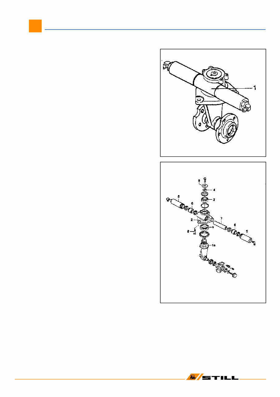
! STILL GmbH Position as per: 4/2002 ( Replaces version: ) 02 Workshop Manual 2008 - 14, 2015 i, 2018 - 24 03 Steer axle (turnable) Steer axle - Mechanical configuration The steer axle (1) is designed as a steering turnable which is fastened with three hex head bolts (8) to the counterweight. The axle shaft (1a) is supported in the housing (2) with tapered roller bearings (3). The end play can be adjusted with shims (4). The pistons (6) of the two geometrically arran- ged steer cylinders act on a toothed rack (7), rotating it via the axle shaft (1a) toothing. 1a = Axle shaft 2 = Housing 3 = Tapered roller bearing 4 = Shim 5 = Cylinder tube 6 = Piston 7 = Toothed rack 8 = Hex head bolt
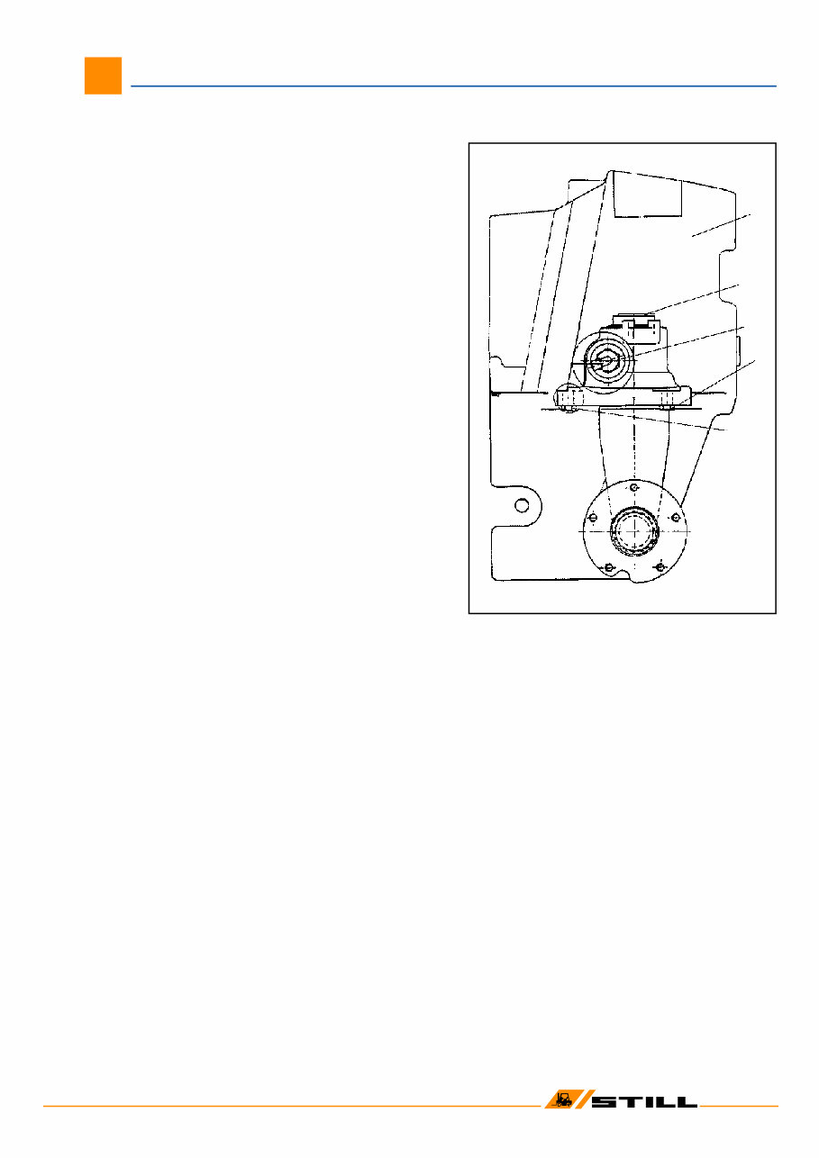
! STILL GmbH Position as per: 4/2002 ( Replaces version: ) 02 Workshop Manual 2008 - 14, 2015 i, 2018 - 24 04 3 4 4 1 2 Steer axle Steer axle removal - Slightly slacken the bolts on the wheels. - Raise the rear end of the truck by at least 15 cm and support with wooden bocks. Securely chock the front wheels to prevent the truck from rolling. - Remove the wheels . - Disconnect the hydraulic fittings (3) on the steer cylinder: Note: Hydraulic oil will run out. - Loosen the tree hex head bolts (4) (are secu- red with Loctite 242). - Remove thed steer axle. 1 Counterweight 2 Curve switch 3 Steer cylinder hydraulic fittings 4 Hex hd bolts M16 x 80 secured with Loctite 242 ( torque loading 195 Nm) Steer axle installation Reverse the removal procedure. In doing this, place wooden blocks under the steer axle and use two hex head bolts as fitting aid. Clean the bolts (4) in a degeasing agent , apply Loctite 242 and torque to 195 Nm.
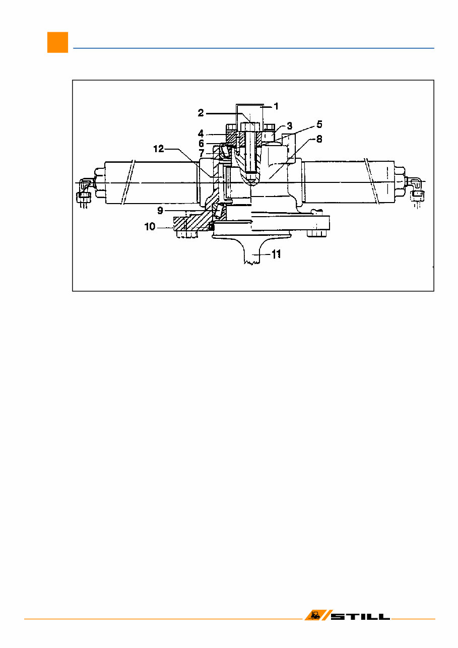
! STILL GmbH Position as per: 4/2002 ( Replaces version: ) 02 Workshop Manual 2008 - 14, 2015 i, 2018 - 24 05 - Remove mount for curve switch (1). - Remove the hex head bolt (2). - Remove washer (3) along with roll pin (4). - Remove the shims (5). - Remove the sealing ring (6). - Remove the top tapered roller bearing (7). - Remove casing (8) along with steer cylinder. - Remove the bottom tapered roller bearing (9) from the axle shaft (11). - The shaft seeling ring (10) can be removed now. 1 Mount for curve switch 2 Hex head bolts 3 Washer 4 Roll pin 5 Shim 6 Sealing ring 7 Top tapered rollerbearing 8 Casing 9 Bottom tapered roller bearing 10 Shaft sealing ring 11 Axle shaft 12 Cavity in casing for grease Steering turnable bearing – Dismantling
This is a highly detailed factory service repair manual for the Still R20-15, R20-16, R20-18, R20-20 Series Electric Fork Truck Forklift. The manual provides step-by-step instructions and detailed illustrations, making it suitable for both do-it-yourself enthusiasts and experienced mechanics. It covers the complete disassembly of the machine, including chassis frame, steer axle, drive unit, wheel/tyres, steering, brake system, electrical installation, electrical equipment, hydraulic pump, drive motor, pump motor, pressure regulator units I and II, pressure regulator unit, control valve block, mast unit, fork carriage, tilt cylinders, system diagnosis, measuring instruments, and test equipment.
Models Covered:
Still R20-15 Electric Fork Truck Forklift
Still R20-16 Electric Fork Truck Forklift
Still R20-18 Electric Fork Truck Forklift
Still R20-20 Series Electric Fork Truck Forklift
File Format: PDF
Compatibility: All Versions of Windows & Mac
Language: English
Requirements: Adobe Reader & WinZip
No waiting, buy from a responsible seller and get instant access. All pages are printable. This manual is a cost-effective way to ensure the proper functioning of your vehicle.
Recently Viewed
5,521,897Happy Clients
2,594,462eManuals
1,120,453Trusted Sellers
15Years in Business
Price:
Actual Price:
Still R20-15, R20-16, R20-18, R20-20 Series Electric Fork Truck Forklift Service Repair Workshop Manual